V. WIRING THE LL916 U/W SPEAKER, AC205B XFMR BOX, Peavey IPA1502 or UMA1502 AMPLIFIER
IMPORTANT!: Mount amplifier and audio equipment in a vented cabinet or equipment rack, located in a humidity
free area. Connect AC powered audio equipment to audio grade power strip and GFCI outlet as required under
National Electric Code. Test GFCI before each use. Always vacate the water at the first sign of inclement weather
and lightning storms. Avoid microphone feedback and/or excessive sound levels, which can be harmful to
speakers and human hearing. Caution: Do not exceed 25 volts rms to the input of the AC205B box.
Exceeding this power will burn out the underwater speaker, which will not be covered under the warranty.
We recommend the Peavey amplifiers listed in our literature -- meets all low voltage safety requirements
(grounded power cord, UL commercial sound listing) AND provides speaker protection circuit to help
prevent burnout.
1.
For 1 to 4 speaker installations, use Peavey IPA1502 power amplifier or UMA1502 mixer/amplifier;
For 5 to 8 speaker installations, use Peavey IPA300T amplifier. Amplifier meets all NEC & UL safety
requirements including grounded power cord (for connection to GFCI outlet), UL Commercial Sound
Listing (UL813), Class-2 wiring rating, and 25V and
COMMON
speaker connections with speaker
protection circuit.
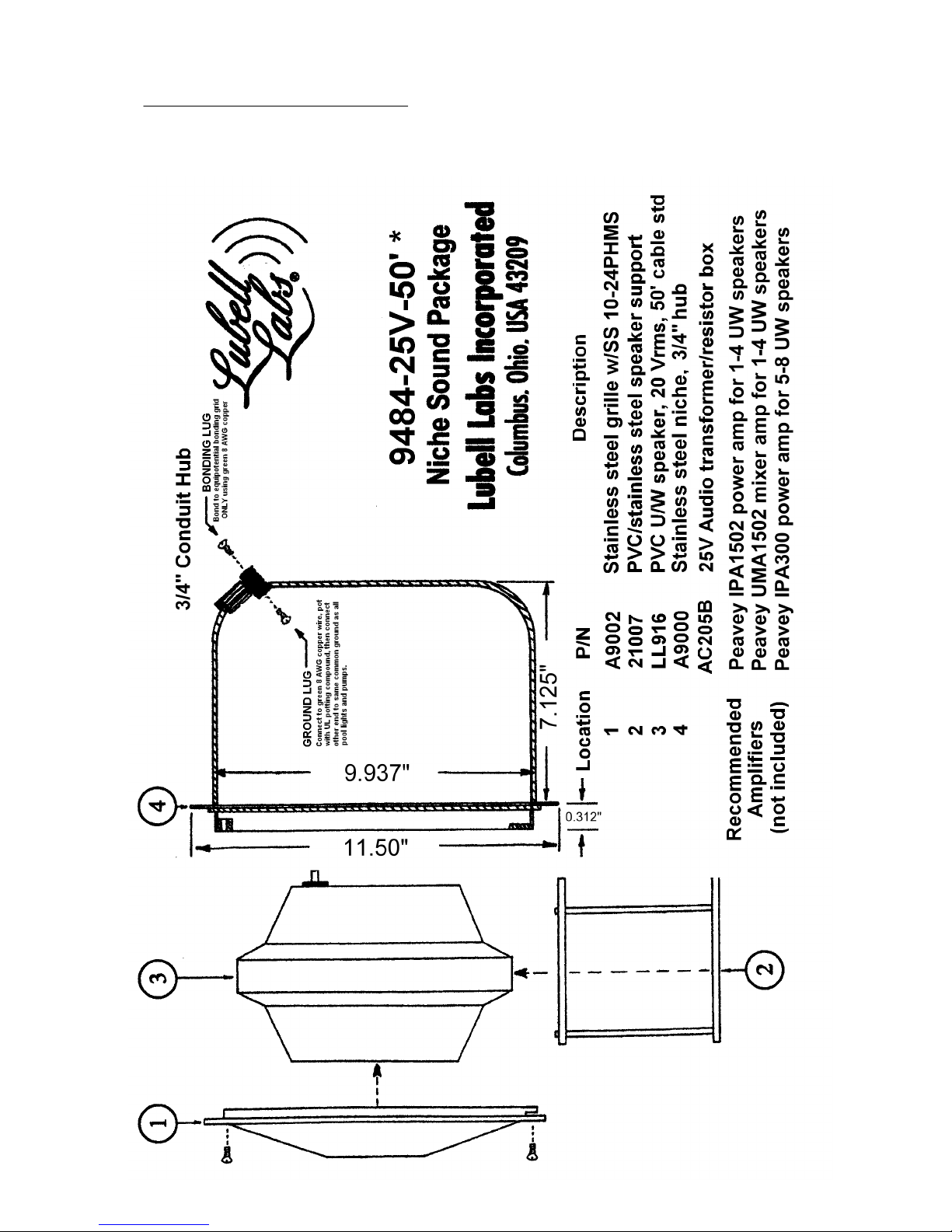
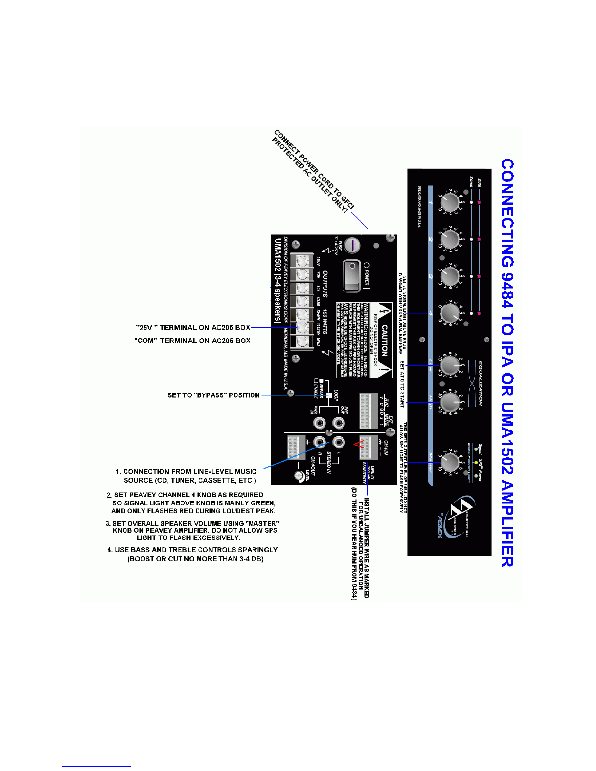
2.
Using a short 18 gauge speaker cable, connect “25V” screw terminal on Lubell AC205B box to “25V”
speaker terminal on amplifier, then connect “
COM
” screw terminal on Lubell AC205B box to
COMMON
speaker terminal on amplifier. Use one AC205B transformer box for each speaker installed, and
connect multiple boxes in parallel/phase only.
3.
Connect black wire from LL916 underwater speaker to “B” screw terminal on Lubell AC205B box, then
connect white wire from LL916 underwater speaker to “W” screw terminal on Lubell AC205B box.
Green ground wire from LL916 underwater speaker may be connected to common pool ground per
paragraph IV section 7 on previous page. Follow ALL local, national, and international electrical code
regulations.
4.
With power off, connect amplifier and any interconnected equipment to an audio grade surge
protected power strip; connect outlet strip to GFCI outlet only; Test GFCI before each use.
5.
Connect audio source (CD player, tuner, network device) to
AUX
input on Peavey IPA1502 amplifier or
UMA1502 mixer/amplifier.
6.
The Peavey amplifiers come with plastic screw terminal blocks, do not discard. The AUX input jack(s)
are factory set to “balanced” wiring. If you wish to convert these input jack(s) to “unbalanced” wiring
(due to ground loop resulting in hum), then please plug in the terminal block and install a 1” jumper
wire betwen the “
GROUND
” terminal block screw and the “-” INPUT terminal block screw.
7.
Set the
LOOP
switch on rear of Peavey IPA1502 or UMA1502 to BYPASS position (unless using
outboard equalizer), or you will not get any sound. Set the “60Hz LOW CUT” switch to “ON” position.
8.
Set UMA1502 tone controls and any outboard tone and/or equalizer controls to "flat" (0) position. Set
channel 4 (AUX) volume control on UMA1502 amplifier to 8 (N/A on IPA1502). Make sure
MASTER
VOLUME
control on IPA1502 and UMA1502 is set to 0 to start.
9.
Turn on power to the house audio system, and to the IPA1502 or UMA1502 amplifier. With loudest
passage of music playing from audio sounce (CD, tuner, network), verify that Peavey channel 4 signal
light is flashing green, but not red (UMA1502 only). If red, reduce channel 4 volume control.
10.
While monitoring the underwater sound, turn up the IPA1502 or UMA1502
MASTER
volume control
until the sound level from the underwater speaker is adequate to swimmers but not so high that the
SPS light or clip light flashes frequently. The SIGNAL light by the
MASTER
control will indicate that
music is being sent to the underwater speaker by flashing green. DO NOT exceed comfortable sound
level or level that causes the
SPS
or
CLIP
light to flash constantly. (SPS light indicated soft clipping,
and should only flash on peaks.)
9484-25V-50’ * APPLICATION & INSTALLATION GUIDE
Page 2
2014 Lubell Labs Inc. All information subject to change without notice