IMPORTANT: THIS GUIDE SUPPLIMENTS HAYWARD NICHE MANUAL AND BOSCH AMPLIFIER MANUAL
I. DESCRIPTION: The Lubell 9484 is a professional 37.5 watt 25V in-wall underwater speaker kit intended for
contractor installation at 4’ (1.22 m) to 6’ (1.83 meter) depth during new concrete or gunite pool construction
utilizing standard or saltwater chlorination systems. DO NOT INSTALL in vinyl liner pools or concrete pools
having vinyl liner due to poor acoustics.
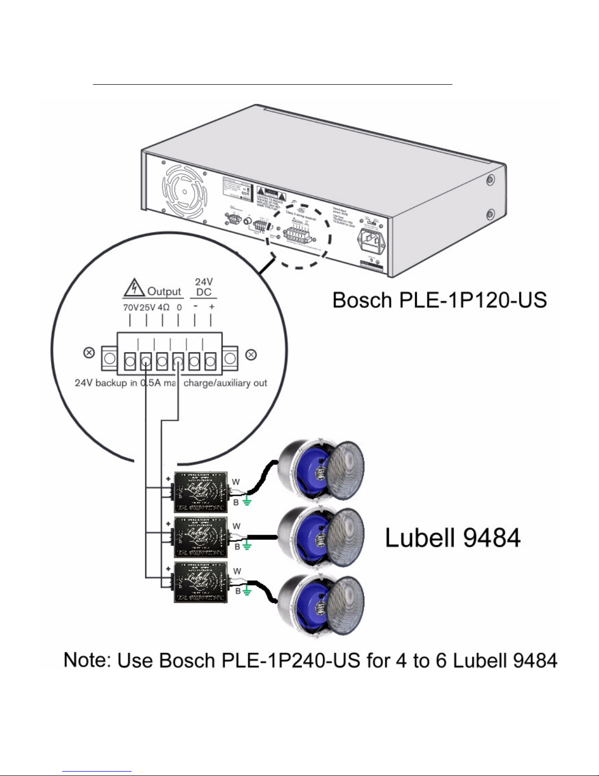
Per page 4 pictorial, the 9484 includes: A9000 (Hayward SP0604C4) stainless steel wet niche with 3/4” bronze
conduit hub, A9002A stainless steel grille, LL916 underwater speaker, 21007 PVC/stainless steel speaker support,
AC205B 25V audio transformer/resistor box). The LL916 speaker is fitted with choice of 50', 100', 150', or 200'
3-conductor cable that runs through conduit to above ground J-box. (Extra cable can be coiled inside the niche for
future on-deck inspections.)
II. LOCATING THE SPEAKERS
Install one 9484 kit for each 20 foot x 20 foot (6.1 m x 6.1 m) section of pool. See last paragraph of online brochure
http://www.lubell.com/9484.html for location diagrams of typical pools. Use two 9484 kits for 20' x 40' pools and
locate 10' from each end either in common wall or catty-corner in long axis walls at 5'-6’ depth. Use three units for
20' x 60' pool and locate one unit 10' from each end at 5'-6’ depth in common 60' wall; Locate third unit in center of
opposite wall at 5'-6’ depth. For 25 yard Olympic pool, locate two units in each 25 yard wall (4 total) 18.75' from
each end at 6' depth. For 50 meter Olympic pool, locate four units in each 50m wall (8 total) at 6' depth at following
distance from ends: 6.25m, 18.75m, 31.25m, 43.75m. Installation at 5’-6’ depth is recommended, but units in shallow
end may be reduced to 4’ depth with some loss of low frequency response and reduced sound level. Install in flat
section of wall only, as grille must mount flush. For large municipal pools, the speakers should be located around the
periphery of the pool for proper sound distribution.
III. INSTALLING THE A9000/2 NICHE/GRILLE
(LICENSED POOL CONTRACTOR/ELECTRICIAN ONLY)
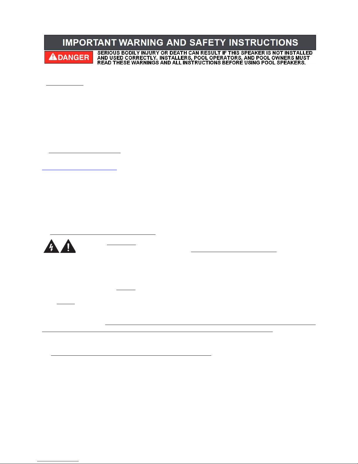
WARNING - EXTERNAL BONDING LUG ON ALL SPEAKER NICHES, LUMINARY NICHES, AND
POOL FIXTURES MUST BE BONDED TO AN EQUIPOTENTIAL BONDING GRID WITH A SOLID
COPPER CONDUCTOR NOT SMALLER THAN 8 AWG PER NATIONAL ELECTRIC CODE
SECTION 680. FAILURE TO FOLLOW THIS CRITICAL PROCEDURE CAN RESULT IN ELECTRICAL SHOCK
AND ELECTROLYSIS DAMAGE TO FIXTURES. FOLLOW ALL INSTRUCTIONS INCLUDED WITH WET-NICHE.
1) Rough in each A9000 wet-niche (Hayward SP0604C4) at 6’ depth in positions recommended above in
COVERAGE section, bonding external lug to equipotential bonding grid per NEC 680.26(B)(1). Run conduit to
nearby above water J-box,; Run conduit from J-box to air conditioned equipment room. WARNING: GROUNDING
LUG INSIDE UNDERWATER SPEAKER NICHE MUST BE GROUNDED AND POTTED TO THE SAME
COMMON GROUND AS ALL LIGHT NICHES, PUMPS, AND FIXTURES USING GREEN 8 AWG COPPER
WIRE PER NEC 680. If local code requires sealed conduit, then seal conduit opening inside niche with approved
sealant. 2) IMPORTANT: Observe diagram inside niche to insure that the very foremost edge of niche is finished
flush with the final tiled or painted surface of the pool wall -- area must be flat for grille to seat. 3) IMPORTANT:
Concrete structure around niche flange must be undercut and filled with sealing plaster to insure a proper watertight
seal.
IV. INSTALLING THE LL916 U/W SPEAKER WITH 21007 SUPPORT
1) Insure that grounding lug inside speaker niche is grounded to common pool ground via green 8 AWG copper
wire, and that termination is potted with UL potting compound to prevent deterioration. 2) Insert the V-shaped 21007
speaker support upright into the A9000 niche with long stand-off's facing into niche. 3) Draw LL916 underwater
speaker cable through conduit leaving sufficient cable coiled inside niche for future on-deck inspections. 4) If code
calls for sealed conduit, then apply approved sealant around speaker cable and #8 grounding wire where it enters
conduit hub, and let dry. 5) Gently tilt the LL916 underwater speaker (cable side first) into the niche and place on
21007 stand. 6) Install A9002 grille, being careful not to overtighten screws. 7) Terminate the green U/W speaker
ground wire along with the green niche ground wire (8 AWG copper) to the same common pool ground as all pool
light niches and pumps. 8) Splice the speaker's black and white wires to two-conductor speaker wire (Class 2 rated):
16 gauge for <100' run; 14 gauge for 100'-200' run; Use direct burial cable for non-conduit installations.
9484-25V-50’ * APPLICATION & INSTALLATION GUIDE
Page 1
2016 Lubell Labs Inc. All information subject to change without notice