Lubeworks GUL002 User manual

Manual
1:1 High Ratio Oil Pump

of 7
1
The Manual of Oil Pump
Read the following precautions and instructions before you begin assembly or using.
Failure to comply with these instructions could result in personal injury or property
damage. Keep these instructions in a convenient location for future reference.
Important Note
The guarantee will be void if the pump has been altered in any way.
Profile
Oil pumps can be used to transfer lubrication oil, waste oil and antifreeze liquids.
This manual is applicable to the following pump only, please confirm your pump is included.
Specification
Item No.
1701004
1701005
1701006
Compression Ratio
1:1
Operating Pressure(bar/psi)
5-8 / 70-115
Max. fluid Pressure (bar/psi)
8/115
Air Consumption (L/min M3/hour)
130/4.7
Capacity (L/min Gallon/min)
32/8.5
Tube Diameter (mm/inch)
42/1.65
Suction Tube Length (mm/inch)
Wall installed /
Extension transfer
730/28.7
940/37
Air Inlet Connection
1/4”quick plug / 1/4”NPT female
Oil delivery Connection
Male 3/4”
Max. Viscosity Oil Delivered
SAE 120
Temperature Oil Delivered
-10~50℃
Noise Level (dB)
82

of 7
2
1:1 Series Oil Pump Exploded View

of 7
3
1:1 Series Oil Pump Part List
Appendix
Code
Name
Quantity
Code
Name
Quantity
1
Air motor cover
1
29
Piston connect cover
1
2
O-ring
1
30
Suction tube
1
3
Air motor shell inside
1
31
Piston shaft
1
4
Slider
1
32
Connector
1
5
Press piece
1
33
O-ring
1
6
Screw
2
34
Spring circlip
1
7
Small circlip
1
35
Ball
1
8
Quick coupling
1
36
Valve seat
1
9
Air center cover
1
37
Filter
1
10
Silencer
1
38
Nut
2
11
Circlip
1
39
U seal
1
12
O-ring
1
40
Small piston
1
13
Securing washer
1
41
O-ring
1
14
Goasket
1
42
Retainer
1
15
Soft gasket
1
43
Connector shaft
1
16
Trip shoe guide
2
44
Piston stem
1
17
Spring seat
2
45
O-ring
1
18
Spring
2
46
U seal
1
19
Spring shell
2
47
O-ring
1
20
O-ring
1
48
Nut
1
21
O-ring
1
49
Shaft
1
22
Bracket
1
50
Piston
1
23
O-ring
2
51
Screw
1
24
Piston cover
1
52
Bracket
1
25
Cut cover
1
53
Silencer
1
26
O-ring
1
54
Air control center
1
27
Side cover
1
55
Slider
1
28
Outlet
1
Troubleshooting
Problem
Possible Causes
Solutions
The pump continues to operate after
the gun trigger has been released
1. The is a oil leak at some point of the
circuit
2. Valve sets (part No.24 and 208, 209,
210, 205, 206) close incorrectly due
to dirt or wearing.
1. Check and tighten unions. Repair
the leak.
2. Substitute damaged elements.
Reduction of the oil delivery. or
reduced pressure in the oil delivery.
1. Silencer (105) dirtied
2. Blocked at some point of the oil
circuit
3. Ball valve set (31, 108) closes
incorrectly due to dirt or wearing.
1. Clean or recharge silencer
2. Use clean oil
3. Substitute damaged elements
Air loss through the air exhaust
1. The sliding valve (7) does not close
properly.
2. Broken press piece (6)
3. Damaged O-ring (203,204)
4. Damaged piston (19)
5. Broken spring (12)
1. Disassemble and clean. Substitute in
case of damage.
2. Substitute damaged elements
Oil leaks through the air exhaust
Seal set (208, 210) damaged
Substitute damaged elements
If the pump has anything wrong, please contact dealer or their technical supporter.
We don’t recommend customer repair the pump themselves.

of 7
4
Storage and Maintenance
Pumps are delivered in appropriate carton boxes. Packaging material should be properly
disposed.
Handling and storage of the new pump do not require any special procedures.
However after the pump has been used, empty the used oil in the suction tube into an
appropriate container. This is done by overturning the pump.
The dust in compressed air can slow down and even block the motor cylinder. The
following steps may prevent this from happening:
1) Let in 50 gram of Vaseline oil or other lubricator from the air inlet hole weekly, operate
the pump for several minutes after having lubricator.
2) Turn on the pump for several minutes until moving parts is fully lubricated.
3) You may repeat the above operation if necessary.
4) The above steps should be carried out on a weekly base.
For the pumps that are attached with compressed air treatment equipment, please empty the
water retained in the reservoir of the filter-purger frequently.
For the pumps that are attached with a lubricator, please pay close attention to the lubricator’s
oil level and refill with SAE 20, SAE 30 or antifreeze oil for extreme conditions when
necessary.
Note:
The user should perform only routine maintenance operations (such as filters, silencers,
cleaning…) with the pump in order not to damage it or compromise its safety.
Contact our sales or service center when the pump needs further maintenance.
General Safety Regulations
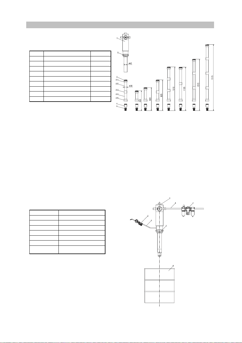
When the pump is connected to the compressed air supply:
1. The compressed air must be filtered to avoid dust and moisture into pump
2. The max compressed air pressure must not exceed 0.8Mpa/120psi
3. To deliver oil, press the knob on the delivery pistol; delivery stops when the knob is
released but the whole system remains under pressure
4. Position the pistol so that the circuit can’t open accidentally. Otherwise oil could leak

of 7
5
onto the ground
5. Never point the pistol at people or object.
6. Press the pistol knob
7. Always cut off the air supply after use so that oil can’t leak out in case one of the pump’s
components should break
8. Use only original spare parts in case the pump has to be repaired or its components have
to be replaced
9. Empty all the oil from the pump in case it has to be disposed of
10. When not in use, turn off compressed air to stop pump
11. Do not use the pump near open flames. Do not smoke during this operation
12. Wear oil-proof gloves
13. Do not throw the oil away. Used oil has to be disposed of according to national
environmental regulations
14. The pumps can be used only to deliver lubricants, used oil or antifreeze liquids. Do not
use the pump for any other substance
How to Use
Directly Fitted Pump into the Drum
1. Insert the suction tube of pump into the drum and secure with ring nut, suitable for
commercial drums with 57 diameter hole and threading 2”BSP
2. Fit a oil delivery tube for oil outlet of the air operated pump using only high quality tubes
(normally 3/4”, according to DIN-SAE norms(), by means of 3/4”BSP threading fitting.
3. Oil delivery pistol: Connect delivery tube with delivery pistol using suitable pipe fittings,
and point the pistol at right place.
4. Air inlet connection is 1/4”quick plug ( or 1/4”NPT female) in all versions. Compressed
air connection ( to be supplied by the customer) should be done using suitable tube.
5. A pressure regulator to keep the pump’s working pressure at the best possible level (max
5-8 bar) between the pump and the compressed air line
6. A cut-off switch can enable the operator to stop the pump at any given moment by cutting
the air supply off between the pump and the compressed air line
7. Switch on all switch.

of 7
6
Wall Installed
Part List
Code
Name
Quantity
1
Oil pump
1
2
Wall bracket
1
3
Pump adapter
1
4
Flexible suction hose
1
5
Suction hose adapter
1
6
Bung adapter
1
7
Rigid suction tube
1
8
Spring circlip
1
9
Ball
1
10
Valve seat
1
11
Filter
1
Proceed As Follows
1. Secure the bracket to the wall using the dowels at about 1200mm height appropriate for
the tank’s dimensions. Make sure that the wall is solid and thick enough for the dowels.
Do not interfere with hydraulic tubes or electric lines.
2. Secure the pump to the bracket 2
3. Connect the flexible suction tube 4 to the pump using the clamp provided.
4. Connect the rigid suction 7 to the end of the flexible suction tube 4 using the elastic
clamp provided
5. Put the bung adapter 6 into the drum hole.
6. Put the rigid suction tube 7 into the pump and secure it in place

of 7
7
Extension Transfer
Part List
Code
Name
Quantity
1
Oil pump
1
2
Bung adapter
1
3-1
Top connection
1
3-2
Extension 500mm tube
1
3-3
Extension sleeve
1
3-4
Extension 200mm tube
1
3-5
Foot connection
1
4
Foot valve
1
5
Filter
1
Proceed as follows
1. Depending on the length of the suction tube the desired extension length. Can be realized
by using the modular extension elements (See the examples given above)
2. Example of possible application to pump with drum or rigid suction tube for obtaining
personalized lengths according to needs.
3. Remove filter and foot valve from the stub pump, screw the extension tube on (W/top
connection), then screw filter and foot valve on the extension tube (foot connection end!)
Connect the Pump with Other Accessories:
Part List
Code
Name
1
Oil pump
2
Bung adapter
3
Oil pistol
4
Hose with fitting
5
Air hose with quick coupling
6
Drum
7(7-1, 7-2, 7-3)
Filter, pressure regulator and
lubricator
Table of contents
Other Lubeworks Water Pump manuals
Popular Water Pump manuals by other brands

Flotec
Flotec EVO-MULTIPRESS 340 SX LOGIC SAFE instruction manual

Schmalz
Schmalz EVE-TR 250 AC3-F operating instructions

PSG
PSG MOUVEX S6C Installation operation & maintenance

Macnaught
Macnaught Lubemate L-SSRP instruction manual

Ulvac
Ulvac MD 4U NT Instructions for use

Steinbach
Steinbach SPS 175-1T ORIGINAL OWNER'S MANUAL

Tool Shed
Tool Shed TSPWP manual

Tsurumi Pump
Tsurumi Pump HSD2.55S Operation manual

Charles Austen
Charles Austen Blue Diamond MiniBlue installation instructions

RAASM
RAASM 900D-2100 manual

Larzep
Larzep W00307 INSTRUCTIONS & MAINTENANCE SHEET

CRANE PUMPS & SYSTEMS
CRANE PUMPS & SYSTEMS Three Phase Simplex Installation Instructions and Operation/Troubleshooting Manual