Lubing TwinClean Line User manual

Drinking
systems
Assembly instructions and
operators manual
Floor watering system TwinClean Line
lubingsystem.com
lubingsystem.com
lubingsystem.com
lubingsystem.com
lubingsystem.com
lubingsystem.com
lubingsystem.com
lubingsystem.com
lubingsystem.com
lubingsystem.com
lubingsystem.com
lubingsystem.com
lubingsystem.com
lubingsystem.com
lubingsystem.com
lubingsystem.com
lubingsystem.com
lubingsystem.com
lubingsystem.com
lubingsystem.com
c
om
l
ubin
g
s
y
stem.c
om
lub
i
n
g
s
y
stem.c
om
lubin
g
s
y
stem.
com
l
ub
i
n
g
s
y
stem.c
om
lub
i
n
g
s
y
stem.co
m
lub
i
ngsystem.co
m
l
ub
i
ngsystem.
com
l
ub
i
ngsystem.c
om
lubingsystem.com
lubingsystem.com

lubingsystem.com
lubingsystem.com
lubingsystem.com
lubingsystem.com
lubingsystem.com
lubingsystem.com
lubingsystem.com
lubingsystem.com
lubingsystem.com
lubingsystem.com
lubingsystem.com
lubingsystem.com
lubingsystem.com
lubingsystem.com
lubingsystem.com
lubingsystem.com
lubingsystem.com
lubingsystem.com
lubingsystem.com
lubingsystem.com
c
om
l
ubin
g
s
y
stem.c
om
lub
i
n
g
s
y
stem.c
om
lubin
g
s
y
stem.
com
l
ub
i
n
g
s
y
stem.c
om
lub
i
n
g
s
y
stem.co
m
lub
i
ngsystem.co
m
l
ub
i
ngsystem.
com
l
ub
i
ngsystem.c
om
lubingsystem.com
lubingsystem.com

Drinking systems
floor watering system TwinClean Line
Copyright © 2018 Lubing System - All rights reserved
3
Document data
File name: Assembly instructions and operators manual - Floor watering system TwinClean Line
Version: 1.0
First issued: 07.11.2011
Last modified: 07.04.2014
Dear Reader,
Permanent development of our products and innovative new designs mean that our assembly and operating
instructions as well as spare parts sheets are regularly updated. If you have any queries, please contact us or your
LUBING dealer.
Current status online at: www.lubingsystem.com
©2018 Lubing System srl.
All rights reserved. Reprints, incl. excerpts thereof, only with authorisation of the company.
lubingsystem.com
lubingsystem.com
lubingsystem.com
lubingsystem.com
lubingsystem.com
lubingsystem.com
lubingsystem.com
lubingsystem.com
lubingsystem.com
lubingsystem.com
lubingsystem.com
lubingsystem.com
lubingsystem.com
lubingsystem.com
lubingsystem.com
lubingsystem.com
lubingsystem.com
lubingsystem.com
lubingsystem.com
lubingsystem.com
c
om
l
ubin
g
s
y
stem.c
om
lub
i
n
g
s
y
stem.c
om
lubin
g
s
y
stem.
com
l
ub
i
n
g
s
y
stem.c
om
lub
i
n
g
s
y
stem.co
m
lub
i
ngsystem.co
m
l
ub
i
ngsystem.
com
l
ub
i
ngsystem.c
om
lubingsystem.com
lubingsystem.com

Drinking systems
floor watering system TwinClean Line
Copyright © 2018 Lubing System - All rights reserved
4
INDICE
1. INTRODUCTION.............................................................................................................................6
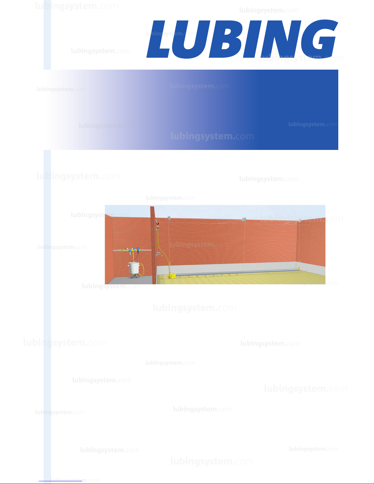
1.1 Brief description of LUBING watering systems for floor watering.................................................6
1.2 Designated use...........................................................................................................................6
2. GENERAL INFORMATION.............................................................................................................6
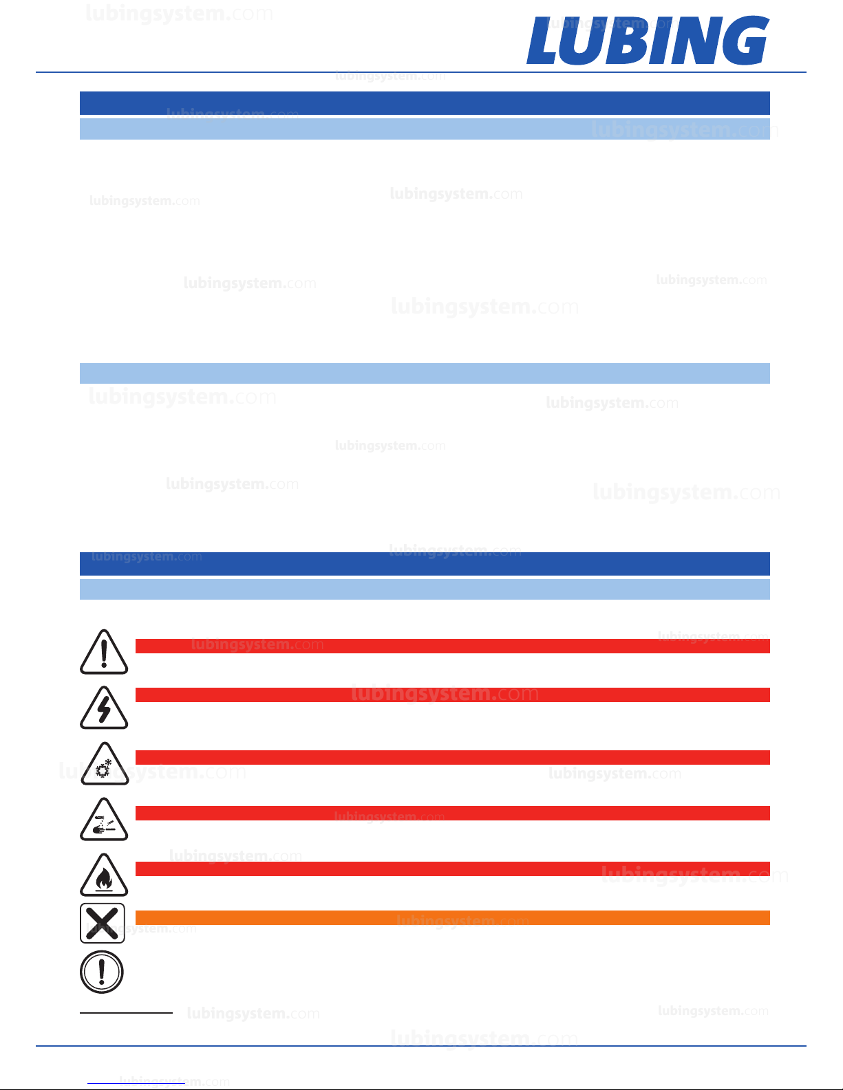
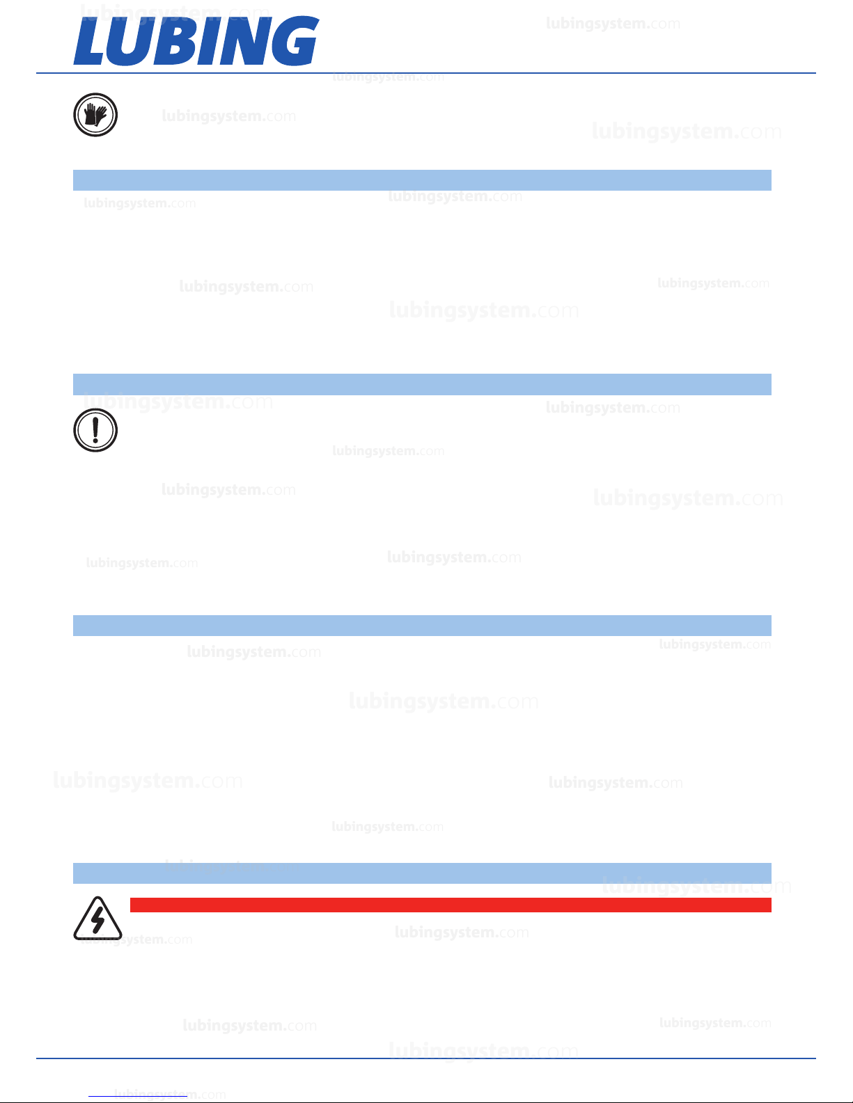
2.1 Warnings and symbols...............................................................................................................6
2.2 General safety guidelines............................................................................................................7
2.3 Obligations.................................................................................................................................7
2.4 Warranty and liability...................................................................................................................7
2.5 Electrical system.........................................................................................................................7
3. ASSEMBLY.....................................................................................................................................8
3.1 Assembly information.................................................................................................................8
3.2 Assembly order...........................................................................................................................8
3.3 Spare parts.................................................................................................................................8
3.4 Assembly overview.....................................................................................................................8
3.4.1 Principal design of LUBING nipple watering systems...........................................................8
3.4.2 Fitting the main water supply..............................................................................................9
3.4.2.1 Mixer...................................................................................................................10
3.4.2.2 Connection accessories......................................................................................10
3.4.2.3 Fitting the water connection kit............................................................................11
3.4.2.4 Glued connections...............................................................................................11
3.4.3 Fitting the drinking line.....................................................................................................12
3.4.3.1 Mounting the hand winches.................................................................................12
3.4.3.2 Mounting the ceiling winches...............................................................................13
3.4.4 Pressure regulating units..................................................................................................14
3.4.4.1 Pressure regulator................................................................................................14
3.4.5 Connecting of the drinking elements................................................................................16
3.4.6 End piece.........................................................................................................................17
4. OPERATING INSTRUCTIONS.....................................................................................................17
4.1 Arrangement of the nipple drinking lines....................................................................................19
4.2 Before hutching........................................................................................................................19
4.2.1 Cleaning..........................................................................................................................19
4.2.1.1 Cleaning the nipple drinking system of dirt and lime accumulation........................19
4.2.1.2 General cleaning of the drinking systems via medicator........................................20
4.2.1.3 Cleaning the nipple drinking system of algaes and accumulations of medicaments..20
4.2.2 Cleaning of the dosers (if available)...................................................................................22
4.2.3 Cleaning of the water filter................................................................................................22
4.3 Vaccinating via drinking water...................................................................................................22
4.4 Hutching in...............................................................................................................................22
4.5 While rearing............................................................................................................................22
4.6 While finishing..........................................................................................................................22
4.7 Between the circles..................................................................................................................22
4.8 Flushing....................................................................................................................................22
4.9 Height table..............................................................................................................................23
4.10 Resistance to chemicals of the drinker components...............................................................24
4.11 Timer for magnetic valve.........................................................................................................24
4.12 Wiring diagram circulation unit................................................................................................25
4.13 Attendance and maintenance.................................................................................................25
lubingsystem.com
lubingsystem.com
lubingsystem.com
lubingsystem.com
lubingsystem.com
lubingsystem.com
lubingsystem.com
lubingsystem.com
lubingsystem.com
lubingsystem.com
lubingsystem.com
lubingsystem.com
lubingsystem.com
lubingsystem.com
lubingsystem.com
lubingsystem.com
lubingsystem.com
lubingsystem.com
lubingsystem.com
lubingsystem.com
c
om
l
ubin
g
s
y
stem.c
om
lub
i
n
g
s
y
stem.c
om
lubin
g
s
y
stem.
com
l
ub
i
n
g
s
y
stem.c
om
lub
i
n
g
s
y
stem.co
m
lub
i
ngsystem.co
m
l
ub
i
ngsystem.
com
l
ub
i
ngsystem.c
om
lubingsystem.com
lubingsystem.com

Drinking systems
floor watering system TwinClean Line
Copyright © 2018 Lubing System - All rights reserved
5
4.14 Trouble shooting.....................................................................................................................25
5. NOTES.........................................................................................................................................26
lubingsystem.com
lubingsystem.com
lubingsystem.com
lubingsystem.com
lubingsystem.com
lubingsystem.com
lubingsystem.com
lubingsystem.com
lubingsystem.com
lubingsystem.com
lubingsystem.com
lubingsystem.com
lubingsystem.com
lubingsystem.com
lubingsystem.com
lubingsystem.com
lubingsystem.com
lubingsystem.com
lubingsystem.com
lubingsystem.com
c
om
l
ubin
g
s
y
stem.c
om
lub
i
n
g
s
y
stem.c
om
lubin
g
s
y
stem.
com
l
ub
i
n
g
s
y
stem.c
om
lub
i
n
g
s
y
stem.co
m
lub
i
ngsystem.co
m
l
ub
i
ngsystem.
com
l
ub
i
ngsystem.c
om
lubingsystem.com
lubingsystem.com

Drinking systems
floor watering system TwinClean Line
Copyright © 2018 Lubing System - All rights reserved
6
1. INTRODUCTION
1.1 Brief description of LUBING watering systems for floor watering
LUBING nipple watering systems TwinClean Line for poultry1supply the animals with drinking water. This requires
the availability of sufficient quantities of fresh and clean drinking water which must be free of contamination and
easily accessible.
LUBING nipple watering systems comprise the following components:
– pressure regulator unit with circulation unit or front supply,
– nipple pipe with nipples and optional cups,
– end piece.
Drinking accessories with:
– main water supply,
– medicator,
– mounting accessories.
1.2 Designated use
LUBING nipple floor watering systems are exclusively intended for standard applications in supplying poultry with
water.
Any other use considered improper. The manufacturer will not be liable for any resulting damages; this risk lies
entirely by the user alone.
Designated use also includes observing all of the information in the operating instructions and compliance with the
inspection and maintenance.
LUBING nipple watering systems may only be operated, maintained and inspected by personnel who are familiar
with these measures and the potential dangers associated with the system.
2. GENERAL INFORMATION
2.1 Warnings and symbols
You will come across the following symbols while reading this manual:
1 Poultry: broiler with or without cups, breeder rearing, breeder, pullets, layer, duck rearing and duck finishing
DANGER!
Warning of electrical hazard!
Warns of dangerous electrical current.
DANGER!
Warns of cold.
DANGER!
Warns of corrosive substances.
DANGER!
Warns of flammable substances.
DANGER!
Warns of general danger.
WARNING
Substances detrimental to health.
WARNING
This warning indicates a hazard which, unless avoided, could involve a low risk of material damage.
lubingsystem.com
lubingsystem.com
lubingsystem.com
lubingsystem.com
lubingsystem.com
lubingsystem.com
lubingsystem.com
lubingsystem.com
lubingsystem.com
lubingsystem.com
lubingsystem.com
lubingsystem.com
lubingsystem.com
lubingsystem.com
lubingsystem.com
lubingsystem.com
lubingsystem.com
lubingsystem.com
lubingsystem.com
lubingsystem.com
c
om
l
ubin
g
s
y
stem.c
om
lub
i
n
g
s
y
stem.c
om
lubin
g
s
y
stem.
com
l
ub
i
n
g
s
y
stem.c
om
lub
i
n
g
s
y
stem.co
m
lub
i
ngsystem.co
m
l
ub
i
ngsystem.
com
l
ub
i
ngsystem.c
om
lubingsystem.com
lubingsystem.com

Drinking systems
floor watering system TwinClean Line
Copyright © 2018 Lubing System - All rights reserved
7
2.2 General safety guidelines
The relevant guidelines for the prevention of accidents as well as other generally recognised technical safety and
medical regulations for the workplace must be observed. Check that the safety and functional equipment works
safely and correctly:
– prior start-up,
– at the appropriate intervals,
– following modifications or maintenance.
The specifications outlined by the water and energy utility companies must also be observed.
These Operating Instructions include the most important information for operating the drinking systems in a safe
manner.
2.3 Obligations
A basic prerequisite for safe handling and smooth operation of this watering system is knowledge of the basic
safety information and safety guidelines. These operating instructions, and the safety instructions in particular,
must be observed by all persons working on the watering system. Furthermore, all regulations and guidelines for
the prevention of accidents for the installation site must also be observed.
The watering system may only be used as designated when it is in a safe technical state. Any problems which may
impair safety must be remedied without delay.
Organisational measures: all safety equipment must be examined at regular intervals.
2.4 Warranty and liability
As a general rule, our general terms and conditions governing sale and supply shall apply.
Warranty and liability claims in the event of personal and material damage are excluded if they are attributable to
one or more of the following causes:
– non-designated use of the watering system,
– improper fitting, commissioning, operation and service of the machine,
– operation of the machine despite defective safety equipment or safety and protective equipment which has
been fitted incorrectly or is non-functional,
– non-observance of the information in the operating instructions as regards transport, storage, fitting,
commissioning, operation, service and equipment of the system,
– independent structural modifications to the system,
– poor supervision of components subject to wear,
– repairs carried out incorrectly,
– catastrophes caused by foreign bodies and forces majeures.
2.5 Electrical system
All tasks extending beyond the framework of system maintenance may only be carried out by qualified personnel.
Always isolate the power supply when working on the device and secure against unauthorised reactivation by
another person.
Examine electrical cables for visible damage prior to commissioning.
Replace any damaged lines before putting the device into operation.
Damaged or destroyed plug devices must be replaced by a qualified electrician.
DANGER!
Warning of electrical hazard!
Always isolate the power supply before working on the electrical system.
NOTE
Mandatory sign indicating protective gloves.
WARNING
Observe information in the operating instructions.
lubingsystem.com
lubingsystem.com
lubingsystem.com
lubingsystem.com
lubingsystem.com
lubingsystem.com
lubingsystem.com
lubingsystem.com
lubingsystem.com
lubingsystem.com
lubingsystem.com
lubingsystem.com
lubingsystem.com
lubingsystem.com
lubingsystem.com
lubingsystem.com
lubingsystem.com
lubingsystem.com
lubingsystem.com
lubingsystem.com
c
om
l
ubin
g
s
y
stem.c
om
lub
i
n
g
s
y
stem.c
om
lubin
g
s
y
stem.
com
l
ub
i
n
g
s
y
stem.c
om
lub
i
n
g
s
y
stem.co
m
lub
i
ngsystem.co
m
l
ub
i
ngsystem.
com
l
ub
i
ngsystem.c
om
lubingsystem.com
lubingsystem.com

Drinking systems
floor watering system TwinClean Line
Copyright © 2018 Lubing System - All rights reserved
8
Do not remove plugs from sockets by pulling the cable.
Covering electrical components can give rise to heat concentration with high temperatures which can in turn
destroy the equipment and cause fires.
3. ASSEMBLY
3.1 Assembly information
Please read the following pages carefully. The instructions in this manual apply for various drinking systems. For
this reason, we would ask you to select and apply the sections which concern you.
When using this manual for LUBING standard versions, please note all alterations to and/or deviations from the
scope of your supply.
3.2 Assembly order
Use the table of contents to find the assembly section you require.
The assembly section describes the individual work steps in the assembly order.
Individual components are provided with position numbers in the drawings. These position numbers can also be
found in the text.
3.3 Spare parts
Spare parts for the nipple drinking system you will find in the Spare parts list for floor watering systems (File
0903).
This contains the exact name of the respective part and its item number, which we require in the event of spare
parts being ordered.
In order to procure electrical components, we require information on the power supply, e.g. 230/400 V – 3 Ph. 50
Hz.
A current version is appended to these assembly and operating instructions.
3.4 Assembly overview
3.4.1 Principal design of LUBING nipple watering systems
1. Water supply
2. Pressure regulator
3. Circulation unit
4. Nipple tube with nipples and possible with cups
5. Couplings
6. Suspension
7. Breather units
1 2 3 4 5 6 7
lubingsystem.com
lubingsystem.com
lubingsystem.com
lubingsystem.com
lubingsystem.com
lubingsystem.com
lubingsystem.com
lubingsystem.com
lubingsystem.com
lubingsystem.com
lubingsystem.com
lubingsystem.com
lubingsystem.com
lubingsystem.com
lubingsystem.com
lubingsystem.com
lubingsystem.com
lubingsystem.com
lubingsystem.com
lubingsystem.com
c
om
l
ubin
g
s
y
stem.c
om
lub
i
n
g
s
y
stem.c
om
lubin
g
s
y
stem.
com
l
ub
i
n
g
s
y
stem.c
om
lub
i
n
g
s
y
stem.co
m
lub
i
ngsystem.co
m
l
ub
i
ngsystem.
com
l
ub
i
ngsystem.c
om
lubingsystem.com
lubingsystem.com

Drinking systems
floor watering system TwinClean Line
Copyright © 2018 Lubing System - All rights reserved
9
3.4.2 Fitting the main water supply
The main water supply should be attached in such a way that it is always protected from frost.
For versions with a solenoid valve, the standard version of the time relais must be connected to a mains voltage of
240 V 50 Hz via the mains plug.
Please note the information on mains voltage on the delivery note.
The components required for the main water supply are supplied ready-assembled.
The attachment (a stable metal console [1]) guarantees a firm, secure and waterproof connection of the components.
The main water supply can therefore be installed on the wall, usually in the front part of the building. The 6 drill holes
[4] in the metal console are 10mm in diameter.
The flange connections [2] permit easy exchange of individual components. The connections to the main water
supply are provide d by the ¾" internal screw threads of the ball valves (inlet and outlet [3]).
When using a medicator please refer to the enclosed instructions.
[3] [4] [1]
[4] [2]
[4]
[3]
DANGER!
Protect from frost.
Frost can destroy the components!
DANGER!
Warning of electrical hazard!
For versions with solenoid valve: fit switching cabinet in such a way that it is protected from water!
lubingsystem.com
lubingsystem.com
lubingsystem.com
lubingsystem.com
lubingsystem.com
lubingsystem.com
lubingsystem.com
lubingsystem.com
lubingsystem.com
lubingsystem.com
lubingsystem.com
lubingsystem.com
lubingsystem.com
lubingsystem.com
lubingsystem.com
lubingsystem.com
lubingsystem.com
lubingsystem.com
lubingsystem.com
lubingsystem.com
c
om
l
ubin
g
s
y
stem.c
om
lub
i
n
g
s
y
stem.c
om
lubin
g
s
y
stem.
com
l
ub
i
n
g
s
y
stem.c
om
lub
i
n
g
s
y
stem.co
m
lub
i
ngsystem.co
m
l
ub
i
ngsystem.
com
l
ub
i
ngsystem.c
om
lubingsystem.com
lubingsystem.com

Drinking systems
floor watering system TwinClean Line
Copyright © 2018 Lubing System - All rights reserved
10
The Main Water Supply is secured horizontally to the point specified in the plans.
Please observe the flow direction (arrow on the water meter) when connecting to the water supply!
Please ensure that there is sufficient space under the main water supply for the mixer, item no. 4248, for 60 litres
(height: 73cm) or mixer, item no. 4258, for 180 litres (height: 97cm) or another container for medication solutions.
There are 3 ways of fitting the reversible flow filter:
1. direct connection: transition Piece DN 50/70 with required pipes and trap
(three 90° bends) in DN 70
2. draining off freely into floor outlet
3. draining off into open
* at 3 bar supply pressure and backwash duration of 15 seconds.
3.4.2.1 Mixer
The LUBING Mixer must stand on a level and even surface.
The water supply connection is achieved via ¾" gardena seals. When using a main water supply, a ¾" hose can
be laid from the ball valve in front of the water meter. This requires a hose connector.
The standard version must be connected to mains voltage of 240 V 60 Hz using a mains plug.
Please observe the information on mains voltage supplied on the delivery note.
3.4.2.2 Connection accessories
LUBING offers a variety of accessories for the water connection. We recommend using the LUBING range of
plastic pipes for pipework into the housing unit. Apart from ø25 mm and 3⁄4", pipes, this range also includes
couplings, bends ,T-pieces, end caps and threaded connection pieces for both pipe diameters permitting all kinds
of pipework layouts. These components must be glued to ensure leak-proof assembly.
Please refer to section “3.4.2.4 Glued Connections”.
The pipe system is secured to the wall or ceiling using ceiling clips, item no. 4349 for the 25 mm pipe and item
no. 4329 for the ¾" pipe. Mark the pipe layout and screw down the holders, item no. 4329/4349. Then press the
pipes into the holders. Check the entire pipe system for leaks prior to commissioning.
LUBING recommends using the water connection kit for connecting the drinking line pressure regulator to the
water supply. Depending on the kit, the following parts are supplied:
WARNING
For versions with medicators: observe overall height of mixers!
WARNING
For versions with reversible flow filter: the backwash water must
be directed towards the waste water channel in such a way that the
possibility of backpressure is eliminated!
WARNING
The connection to a public supply line is made in accordance with the specifications of the responsible
water utility company!
FILTER SIZE BACKWASH VOLUME*
1⁄2" and 3⁄4" 12 litres
1" and 1 1⁄4" 15 litres
1 1⁄2" and 2" 18 litres
Item no. 4150 Clamp ø3⁄4", hose connector, 3 m tube 1⁄2" and clips
Item no. 4151 Clamp ø3⁄4", hose connector, 4 m tube 1⁄2" and clips
Item no. 4152 Clamp ø3⁄4", hose connector, 5 m tube 1⁄2" and clips
Item no. 4153 Clamp ø3⁄4", hose connector, 3 m tube 1⁄2", ball valve and clips
Item no. 4154 Clamp ø3⁄4", hose connector, 4 m tube 1⁄2", ball valve and clips
lubingsystem.com
lubingsystem.com
lubingsystem.com
lubingsystem.com
lubingsystem.com
lubingsystem.com
lubingsystem.com
lubingsystem.com
lubingsystem.com
lubingsystem.com
lubingsystem.com
lubingsystem.com
lubingsystem.com
lubingsystem.com
lubingsystem.com
lubingsystem.com
lubingsystem.com
lubingsystem.com
lubingsystem.com
lubingsystem.com
c
om
l
ubin
g
s
y
stem.c
om
lub
i
n
g
s
y
stem.c
om
lubin
g
s
y
stem.
com
l
ub
i
n
g
s
y
stem.c
om
lub
i
n
g
s
y
stem.co
m
lub
i
ngsystem.co
m
l
ub
i
ngsystem.
com
l
ub
i
ngsystem.c
om
lubingsystem.com
lubingsystem.com

Drinking systems
floor watering system TwinClean Line
Copyright © 2018 Lubing System - All rights reserved
11
3.4.2.3 Fitting the water connection kit
The Clamp must be secured to the 3⁄4” pipe. Do this by drilling a hole 10
mm in diameter (2) in the water pipe.
Securing the clamp:
1. insert the clamp (3) and thorn in the drilled hole on the pipe.
2. make sure the O-ring seal is positioned correctly.
3. place the top part of the clamp (1) on the pipe and secure using the
two screws.
4. secure one end (5) of the hose to the hose connector (4) using the
clip.
5. screw the hose connector to the flat packing in the clamp (3). Insert
the other end of the hose into the pressure regulator (6) hose connector
and secure with a clip. This must be installed with flat packings in the
case of ball valve (7) (see versions on the previous page). If required, the
ball valve can be mounted between the pressure regulator and the hose
connector (see graphic on right) if you wish to have the ball valve directly
on the drinking line. Or you can mount it between the hose connector (4)
and the clamp (3) in order to block the water supply directly at the supply
point.
3.4.2.4 Glued connections
LUBING recommends “Tangit” adhesive, article no. 4405, for glued connections.
Many connection elements in the LUBING product range are designed as glued connections. Please observe the
following manufacturer instructions in order to ensure secure connections.
The pipe must be cut at a right angle and burred. The areas to be glued must be clean and dry. Clean the ends
of the pipe on the outside and the connecting elements on the inside using a cleaning agent (please check
compatibility) and woven felt. Always use new woven felt. The areas to be glued must be fully dry before applying
the adhesive.
Push the pipe and connecting element without twisting until the limit stop and hold tight for a few seconds until the
glue has set. Immediately following joining, remove superfluous glue with the woven felt as otherwise the pipe will
be etched too strongly. Owing to the fast setting features of the adhesive, the join parts must be pushed together
within 4 minutes of applying the glue. The open period for Tangit depends on the ambient temperature and/or film
thickness.
Stress: do not move the pipes for at least 5 minutes after gluing. At temperatures below 10°C, this period is
extended to a minimum of 15 minutes.
Pressure test: the pipes should not be filled nor should a pressure test be carried out until 24 hours after the last
gluing procedure. We recommend rinsing pipes and possibly even leaving them full of water if they are not put into
operation immediately.
Please observe the protective measures described by the manufacturer.
Please also observe additional information in the data sheets and guidelines on the prevention of accidents supplied
by the professional associations, e.g. VBG 15, VBG 81, M017 and the safety data sheets.
WARNING
Ensure that there is no water in the pipe before drilling.
Burr the drill hole. Rinse out any chips from the pipe. Do not
commence assembly of the clamp until after rinsing first.
AMBIENT TEMPERATURE PROCESSING TIME FILM THICKNESS
20 °C approx. 4 min. 1 mm
25 °C 3 min. 1 mm
30 °C 2 min. 1 mm
40 °C 1 min. 1 mm
> 40 °C < 1 min. 1 mm
Item no. 4155 Clamp ø3⁄4", hose connector, 5 m tube 1⁄2", ball valve and clips
lubingsystem.com
lubingsystem.com
lubingsystem.com
lubingsystem.com
lubingsystem.com
lubingsystem.com
lubingsystem.com
lubingsystem.com
lubingsystem.com
lubingsystem.com
lubingsystem.com
lubingsystem.com
lubingsystem.com
lubingsystem.com
lubingsystem.com
lubingsystem.com
lubingsystem.com
lubingsystem.com
lubingsystem.com
lubingsystem.com
c
om
l
ubin
g
s
y
stem.c
om
lub
i
n
g
s
y
stem.c
om
lubin
g
s
y
stem.
com
l
ub
i
n
g
s
y
stem.c
om
lub
i
n
g
s
y
stem.co
m
lub
i
ngsystem.co
m
l
ub
i
ngsystem.
com
l
ub
i
ngsystem.c
om
lubingsystem.com
lubingsystem.com

Drinking systems
floor watering system TwinClean Line
Copyright © 2018 Lubing System - All rights reserved
12
Tangit is highly inflammable. Its solvent vapours are heavier than air and can form explosive mixtures. For this
reason, always ensure sufficient ventilation when processing, drying or gluing using Tangit. In workrooms and
adjoining rooms: No smoking! No welding! No naked flames and avoid generating sparks! Prior to welding work,
accumulations of solvent vapours and explosive mixtures must be removed. Fill pipelines with water, rinse well and
blow through. Do not seal pipes during the drying phase.
Longer inhalation of these solvent vapours can lead to impaired health. Store used woven felt in closed containers.
If the substance comes into contact with the eyes, rinse thoroughly with water and consult a doctor.
Safety advice:
–must be kept out of reach of children,
–keep away from ignition sources – no smoking,
–avoid contact with eyes,
–if ingested, consult a doctor and show packaging or label.
3.4.3 Fitting the drinking line
LUBING drinking lines comprise ready-assembled individual elements 3 metres in length, the pressure regulator,
the circulation unit, ball tank and breather unit.
Suspension units, ropes with adjusting and retaining panels, ceiling pulleys and hooks are used for suspending the
drinking line.
The drinking line is adjusted in height via traction ropes, guide pulleys and handwinches.
The handwinches are secured at the front in the case of short barn buildings. In the case of long barn buildings
(100 - 150 metres), ceiling winches are used in the centre of the barn.
If you have not installed a Main Water Supply line as described in “3.4.2 Fitting the main water supply”, please
observe the following:
– a water filter must be fitted in any case,
– the water supply line via the wall or ceiling should be at least 3⁄4" in diameter. The individual supply line
from the ceiling to the Ball Tanks or Pressure Regulators is laid as a 1⁄2" pressure hose (see “3.4.2.3 Water
connecting kit”).
– if using a proportioning unit, we recommend the LUBING Mixer.
Please assemble as follows:
1. measure the width of the barn, specify the position of the drinking line and sketch it
on the front and back walls of the building. The number of drinking lines per building is
specified in the design.
2. calculate the length of the drinking line and determine the distance between it and
the front and back walls.
3. specify and screw in the first (1) and last (5) ceiling hook for each row.
4. secure a string between the two ceiling hooks (1) and (5).
5. screw in all of the ceiling hooks (4) approx. 3 metres apart and on alternating sides
of the string. They should be approx. 20 cm away from the string.
6. position another ceiling hook 20 cm from the string and opposite the second ceiling
hook (2).
3.4.3.1 Mounting the hand winches
1. Once the ceiling hooks have been inserted for each of the drinking lines, the traction rope is suspended. The
traction rope is placed through the open eyelet of the ceiling hooks for each drinking line and secured to the end
DANGER!
“Tangit” adhesive is highly flammable.
F = easily flammable!
WARNING
Tangit contains tetrahydrofurane and cyclohexanone.
Xi = irritable
Irritates the eyes and breathing apparatus.
NOTE
We recommend wearing protective gloves as a precaution for preventing contact with the skin.
lubingsystem.com
lubingsystem.com
lubingsystem.com
lubingsystem.com
lubingsystem.com
lubingsystem.com
lubingsystem.com
lubingsystem.com
lubingsystem.com
lubingsystem.com
lubingsystem.com
lubingsystem.com
lubingsystem.com
lubingsystem.com
lubingsystem.com
lubingsystem.com
lubingsystem.com
lubingsystem.com
lubingsystem.com
lubingsystem.com
c
om
l
ubin
g
s
y
stem.c
om
lub
i
n
g
s
y
stem.c
om
lubin
g
s
y
stem.
com
l
ub
i
n
g
s
y
stem.c
om
lub
i
n
g
s
y
stem.co
m
lub
i
ngsystem.co
m
l
ub
i
ngsystem.
com
l
ub
i
ngsystem.c
om
lubingsystem.com
lubingsystem.com

Drinking systems
floor watering system TwinClean Line
Copyright © 2018 Lubing System - All rights reserved
13
(ventilation side) of the last ceiling hook.
2. Screw on the deflection pulley and Hand Winch flush to the traction rope on the front wall.
Please observe the enclosed assembly and operating instructions for hand winches.
3. Guide the front end of the traction rope through the guide pulley, pull taut, thread through the manual hoisting
winch receiver, clamp using the attachment screw and regulate the tension using the winch.
4. Remove the traction rope from the ceiling hooks with the exception of the last ceiling hook. Suspend the ceiling
pulleys from each of the ceiling hooks.
3.4.3.2 Mounting the ceiling winches
1. Secure the Ceiling Winch to a load-bearing element in the centre of the house.
2. Secure the traction rope at both ends and pull towards the middle.
3. Secure the traction rope to the Ceiling Winch.
4. Cut the plastic rope to length (length = ceiling height + 20 cm). The first plastic rope must be longer (length
= ceiling height + 20 cm + distance between the first two ceiling pulleys). Guide the plastic rope through the
ceiling pulleys and secure to the traction cable using cable clamps 10 cm in front of each pulley in the direction
CAUTION!
In order to prevent the traction rope from twisting, it must be unwound. Kinks and knots can arise when
unwinding the traction rope.
CAUTION!
The wall must be load-bearing otherwise the entire tensile load will be borne by the deflection pulley.
Please observe the information on the rating plate.
Item. no. 4415 Item. no. 4417/4428
ATTENTION
In order to prevent the traction rope from twisting, it must be unwound. Kinks and knots can arise when
unwinding the traction rope.
lubingsystem.com
lubingsystem.com
lubingsystem.com
lubingsystem.com
lubingsystem.com
lubingsystem.com
lubingsystem.com
lubingsystem.com
lubingsystem.com
lubingsystem.com
lubingsystem.com
lubingsystem.com
lubingsystem.com
lubingsystem.com
lubingsystem.com
lubingsystem.com
lubingsystem.com
lubingsystem.com
lubingsystem.com
lubingsystem.com
c
om
l
ubin
g
s
y
stem.c
om
lub
i
n
g
s
y
stem.c
om
lubin
g
s
y
stem.
com
l
ub
i
n
g
s
y
stem.c
om
lub
i
n
g
s
y
stem.co
m
lub
i
ngsystem.co
m
l
ub
i
ngsystem.
com
l
ub
i
ngsystem.c
om
lubingsystem.com
lubingsystem.com

Drinking systems
floor watering system TwinClean Line
Copyright © 2018 Lubing System - All rights reserved
14
5. Link the plastic rope with the traction cable at the last ceiling pulley.
6. Unwind the wire, taking care to avoid kinks.
3.4.4 Pressure regulating units
The floor watering system only can be operated with using a pressure regulator. The pressure regulator reduces the
water pressure to the correct operating pressure at the drinking line (please refer to the height chart on page 23).
3.4.4.1 Pressure regulator
The pressure regulator item 3237-00 is supplied pre assembled.
Assembly
Please observe the enclosed assembly and operating Instructions for the pressure regulator. The breather tube at
the 900 mm long breather unit has to be secured contrary to bow away from the side.
CAUTION!
The first plastic rope for the pressure regulator or the ball tank is not secured on the traction cable in front
of the first ceiling pulley. This plastic rope is guided across the first ceiling pulley to another ceiling pulley
at the height of the second ceiling pulley, where it is deflected and linked to the traction cable in front of
the second ceiling pulley.
ATTENTION
Plastic ropes may not scrub at the traction cable!
Traction cable Ceiling hook Ceiling pulley
Cable clamp
Plastic rope
NOTE
In order to avoid damages of the form seal, the following is to be considered before putting the coupling
of the circulation unit into the pressure regulator: Coat the form seal(s) in the transition piece with
lubricant (vaseline, acidless fat, detergent, etc.)!
of traction.
lubingsystem.com
lubingsystem.com
lubingsystem.com
lubingsystem.com
lubingsystem.com
lubingsystem.com
lubingsystem.com
lubingsystem.com
lubingsystem.com
lubingsystem.com
lubingsystem.com
lubingsystem.com
lubingsystem.com
lubingsystem.com
lubingsystem.com
lubingsystem.com
lubingsystem.com
lubingsystem.com
lubingsystem.com
lubingsystem.com
c
om
l
ubin
g
s
y
stem.c
om
lub
i
n
g
s
y
stem.c
om
lubin
g
s
y
stem.
com
l
ub
i
n
g
s
y
stem.c
om
lub
i
n
g
s
y
stem.co
m
lub
i
ngsystem.co
m
l
ub
i
ngsystem.
com
l
ub
i
ngsystem.c
om
lubingsystem.com
lubingsystem.com

Drinking systems
floor watering system TwinClean Line
Copyright © 2018 Lubing System - All rights reserved
15
Front supply with circulating unit
– Push circulation unit (1) with the coupling (2) into the pressure regulator.
– Connect the circulating unit with 2 screws BZ 5,5x13 (a) to the pressure regulator.
– The plastic rope will be connected direct to the hanger (3).
Middle supply with circulation unit
– Fasten the circulation unit (1) as described in the front connecting at one side. Remove plug (6). On the other
side fasten the front supply (4), with coupling (5) to the circulation unit and fasten it to the pressure regulator
with 2 screws BZ 5,5x13 (a).
– Use the hanger (3) of the circulation unit for the suspension with the plastic rope.
The circulation unit needs a supply voltage. Connect the wire at suitable place to the power supply. Please note the
maximum voltage (label at the cover). The voltage is also on the type label of the pump, which will be accessible
by removing the cover.
Front supply without circulating unit
– Push front supply (1) with the coupling (2) into the pressure regulator.
– Connect the front supply with 2 screws BZ 5,5x13 (a) to the pressure regulator.
– The plastic rope will be connected direct to the hanger (3).
3
a
1
2
3
a
1
2
1
3
6a
5
4
ITEM NO. POWER SUPPLY SYSTEM
3401-00 230 V 50 Hz
3413-00 230 V 60 Hz
3412-00 110 V 50 Hz
3411-00 110 V 60 Hz
lubingsystem.com
lubingsystem.com
lubingsystem.com
lubingsystem.com
lubingsystem.com
lubingsystem.com
lubingsystem.com
lubingsystem.com
lubingsystem.com
lubingsystem.com
lubingsystem.com
lubingsystem.com
lubingsystem.com
lubingsystem.com
lubingsystem.com
lubingsystem.com
lubingsystem.com
lubingsystem.com
lubingsystem.com
lubingsystem.com
c
om
l
ubin
g
s
y
stem.c
om
lub
i
n
g
s
y
stem.c
om
lubin
g
s
y
stem.
com
l
ub
i
n
g
s
y
stem.c
om
lub
i
n
g
s
y
stem.co
m
lub
i
ngsystem.co
m
l
ub
i
ngsystem.
com
l
ub
i
ngsystem.c
om
lubingsystem.com
lubingsystem.com

Drinking systems
floor watering system TwinClean Line
Copyright © 2018 Lubing System - All rights reserved
16
Middle supply without circulating unit
– Push front supply (1) with the coupling (2) into the pressure regulator.
– Connect the front supply with 2 screws BZ 5,5x13 (a) to the pressure regulator.
– Remove plugs (6).
– Plug in connector (3) into the front supply.
– Connect middle supply (5) with the pressure regulator and connector.
– Fasten middle supply with 2 screws Z 5,5x13 (a).
– The plastic rope will be connected direct to the hanger (3).
3.4.5 Connecting of the drinking elements
The pressure regulator are placed in the front or in the middle under the ceiling pulley and the end unit at the end.
1. Connect the first drinking element with circulation unit.
2. Push the hanger onto the TwinClean Line profile. Place the hanger beside the coupling.
3. Fasten the first plastic rope to the circulation unit. The plastic ropes are clamped approx. 10 cm over the
hanger with the clamping screw.
4. Fasten the second plastic rope to the end of the first drinking element. Make sure that you hang the element
up at an ergonomic value (approx. 90 cm of the ground). Fasten now the hanger in each case to the end of
the element, fasten the hanging up line and connect then the clutch to the previous drinking element. Push the
couplings of the TwinClean profiles all the way to the Stopp. Pull the clutch by means of the screws can damage
the coupling.
Tighten all 4 mounting bolt, after complete plug together, at the clutch.
Maximum torque: 3.5 Nm.
1
26a
5
3
6
ATTENTION
Push the couplings of the TwinClean profiles all the way to the Stop. Make sure that the drinking element
aligned with the supply unit. Only tighten after that the screws!
Maximum torque: 3.5 Nm
NOTE
In order to avoid damages of the form seal, the following is to be considered before connecting the
coupling: coat the form seal(s) with lubricant (vaseline, acidless fat, detergent, etc.)!
lubingsystem.com
lubingsystem.com
lubingsystem.com
lubingsystem.com
lubingsystem.com
lubingsystem.com
lubingsystem.com
lubingsystem.com
lubingsystem.com
lubingsystem.com
lubingsystem.com
lubingsystem.com
lubingsystem.com
lubingsystem.com
lubingsystem.com
lubingsystem.com
lubingsystem.com
lubingsystem.com
lubingsystem.com
lubingsystem.com
c
om
l
ubin
g
s
y
stem.c
om
lub
i
n
g
s
y
stem.c
om
lubin
g
s
y
stem.
com
l
ub
i
n
g
s
y
stem.c
om
lub
i
n
g
s
y
stem.co
m
lub
i
ngsystem.co
m
l
ub
i
ngsystem.
com
l
ub
i
ngsystem.c
om
lubingsystem.com
lubingsystem.com

Drinking systems
floor watering system TwinClean Line
Copyright © 2018 Lubing System - All rights reserved
17
3.4.6 End piece
1. Push the end piece all the way into the coupling at the end of the drinking line.
2. Tighten all 4 bolts. Maximum torque: 3.5 Nm.
3. Lower the drinking line so that the nipples stand for something over the ground (this facilitates an aligning
of drinking line). The cables are cut off approx. 10 cm before the last ceiling pulley and connected with the last
plastic rope.
4. Hoist the TwinClean Line with the hand winch/ceiling winch on work height (approx. 1 m) and readjust.
Horizontal aligning is made by the clamping screw. For the height adjustmenting the clamping screw is loosened,
so that the plastic rope is movable by the clamping screw. Tighten the clamping screw firmly as soon as the
adjustment has been completed.
5. Connect from the central inlet pipe individual drinking lines with pressure hose ½" and open the water flow.
6. The maximum water pressure for the pressure regulators is 3 bar. Minimum input pressure for the pressure
regulators is 0.4 bar. Set the water level in the pressure regulator by turning the red adjusting wheel.
7. Check the entire system for tightness after completing assembly.
The LUBING floor watering system is operational.
4. OPERATING INSTRUCTIONS
This Operating Instruction describes the handling of the floor watering system TwinClean Line. The general
information are based on our current skills and experiences. Because of the amplitude of possible factors there
can be variations in handling of your drinking system. Please observe your drinking system and check how you can
optimise your results further more at which adjustments and activities.
LUBING suggests every nipple drinker operater to use the drinkers with the quality of drinking water.
The following limit values are defined in Italy:
NAME UNIT LIMIT VALUE
PH-value - 6,5 - 9,5
Calcium mg/l 400
Sulfate mg/l 250
Nitrate mg/l 50
lubingsystem.com
lubingsystem.com
lubingsystem.com
lubingsystem.com
lubingsystem.com
lubingsystem.com
lubingsystem.com
lubingsystem.com
lubingsystem.com
lubingsystem.com
lubingsystem.com
lubingsystem.com
lubingsystem.com
lubingsystem.com
lubingsystem.com
lubingsystem.com
lubingsystem.com
lubingsystem.com
lubingsystem.com
lubingsystem.com
c
om
l
ubin
g
s
y
stem.c
om
lub
i
n
g
s
y
stem.c
om
lubin
g
s
y
stem.
com
l
ub
i
n
g
s
y
stem.c
om
lub
i
n
g
s
y
stem.co
m
lub
i
ngsystem.co
m
l
ub
i
ngsystem.
com
l
ub
i
ngsystem.c
om
lubingsystem.com
lubingsystem.com

Drinking systems
floor watering system TwinClean Line
Copyright © 2018 Lubing System - All rights reserved
18
With these values you reach a long lifetime of your drinking system.
The methode of cleaning depends on the water quality and the added medicaments, vitamins, etc.
The drinking line should be well flushed between at least every cycle. Additives for cleaning see “Cleaning of the
drinking line”.
Please always keep in mind the big influence that the drinking water has on the production results.
Function: the drinking water in the TwinClean Line is continuously circulated inside the drinking line. In addition
a pump is installed in the circulation unit, which pumps the water with defined pressure to the upper line of the
drinking line profile. The water runs to the end and flows back again in the lower nipple pipe to the pump. A float
switch regulates automatically the pump unit. It ensures that the pump do not run without water. As with other
LUBING drinking systems, the height of the water column is set at the pressure regulator. The correct height
adjustment is measured at the breather at the pressure regulator.
The flow rate of the pump can be adjusted with the flow rate controller.
The adjustment depends of the installed drinking line length and is only made once with start-up. The balls in the
two front breathers indicate the difference of pressure between upper and lower line.
The drinking line principle is laid out in such a way that the pressure at the end of drinking line is always higher as
in front at the pressure regulator.
H
The pressure head H of the pump can be adjusted
with the flow rate controller. The adjustment
depends of the installed drinking line length and is
only made once with start-up.
NAME UNIT LIMIT VALUE
Chloride mg/l 250
Iron mg/l 0,2
lubingsystem.com
lubingsystem.com
lubingsystem.com
lubingsystem.com
lubingsystem.com
lubingsystem.com
lubingsystem.com
lubingsystem.com
lubingsystem.com
lubingsystem.com
lubingsystem.com
lubingsystem.com
lubingsystem.com
lubingsystem.com
lubingsystem.com
lubingsystem.com
lubingsystem.com
lubingsystem.com
lubingsystem.com
lubingsystem.com
c
om
l
ubin
g
s
y
stem.c
om
lub
i
n
g
s
y
stem.c
om
lubin
g
s
y
stem.
com
l
ub
i
n
g
s
y
stem.c
om
lub
i
n
g
s
y
stem.co
m
lub
i
ngsystem.co
m
l
ub
i
ngsystem.
com
l
ub
i
ngsystem.c
om
lubingsystem.com
lubingsystem.com

Drinking systems
floor watering system TwinClean Line
Copyright © 2018 Lubing System - All rights reserved
19
4.1 Arrangement of the nipple drinking lines
The number and the distance of drinking lines to each other must be adapted to the number of animals and to the
structural conditions. If you have any questions do not hesitate to contact us.
We provide you also gladly a layout for your individual needs. Pay attention to the maximum number of animals
per nipple!
Radiant heater: the jet direction should run parallel to the drinking line. The drinking line should not be illuminated
directly.
In principle it applies to keep a large distance between heaters and drinking line to avoid unnecessary warming up
of the drinking water.
4.2 Before hutching
The following points are especially to be observed before start-up and even during the operation:
– before start-up the drinking lines have to be well flushed. It must be shure that all lines and cups are completely
free from cleanings and desinfections.
– it must be controlled that there is a sufficient water flow and clean water.
– the water pressure and the supply line have to be checked. The maximum water pressure that is permitted
for the pressure regulator/ball tank is 3 bar.
– pay attention to the uniformed spreading of the litter! Non-uniformed litter complicates the correct height
adjustment.
4.2.1 Cleaning
Before using cleaners, that are not listed in the following cleaning instructions and acids of other aggressive
subjects, the stability list has to be checked. Should the product you want to use not be listed, please ask the
manufacturer for any incompatibility!
4.2.1.1 Cleaning the nipple drinking system of dirt and lime accumulation
LUBING suggests EVC 12 for the application according to the following manufacturing information.
This instruction for cleaning the nipple drinking systems are via medicator. Should this instruction not be identical
to the available system or not realizable, even this instruction is generally for all nipple drinking systems, the
application has to be adjusted to the certain circumstances.
EVC 12 is available in 5 kg containers.
Product datas
At designated application of EVC 12 (maximum resolution of 10% in water T max = 50°C) the following plastics
are consistent:
– plexiglass
– polyvinyl chloride (PVC)
– polyethylene (PE)
– polypropylene (PP)
– fluor caoutchouk (viton A and B)
ATTENTION
At the additions to the drinking water:
– only liquid or water soluble admixtures have to be given to the water,
– after admixture the drinking lines have to be well flushed with clean water.
DANGER!
Non suitable cleanings, acids or other aggressive subjects can destroy the drinking system.
House length 60 m 90 m 120 m
Pressure head H 15 cm 20 cm 25 cm
lubingsystem.com
lubingsystem.com
lubingsystem.com
lubingsystem.com
lubingsystem.com
lubingsystem.com
lubingsystem.com
lubingsystem.com
lubingsystem.com
lubingsystem.com
lubingsystem.com
lubingsystem.com
lubingsystem.com
lubingsystem.com
lubingsystem.com
lubingsystem.com
lubingsystem.com
lubingsystem.com
lubingsystem.com
lubingsystem.com
c
om
l
ubin
g
s
y
stem.c
om
lub
i
n
g
s
y
stem.c
om
lubin
g
s
y
stem.
com
l
ub
i
n
g
s
y
stem.c
om
lub
i
n
g
s
y
stem.co
m
lub
i
ngsystem.co
m
l
ub
i
ngsystem.
com
l
ub
i
ngsystem.c
om
lubingsystem.com
lubingsystem.com

Drinking systems
floor watering system TwinClean Line
Copyright © 2018 Lubing System - All rights reserved
20
Composition and chemical characterisation:
– preperation with powdery acids, dispersing agents and organic inhibitores
– CAS no.: 5329-14-6 77-92-9
– EINECS no: 226-218-8 201-069-1
Identification according to the EG principle:
– Sulf amino acid, concentration > 20%
– citric acid, concentration > 20%
Instructions
Insurance Association: please adhere to the leaflet M004 “Acid Materials”.
The unused product has to apply to a special handling according to the magisterial instructions.
Identification according to dangerous goods (valid for the concentrate):
– Xi: irritating
– R36/38: irritates eyes and skin
– S26: wash out the eyes immediately after getting in touch with them and consult a doctor
– S28: wash the skin immediately with plenty of water after getting in touch with it
4.2.1.2 General cleaning of the drinking systems via medicator
The material requirements for the general cleaning (cleaning and desinfection) depend on the following factors:
1. the water quantity in the drinking system (each 2 metres drinking line approx. 1 litre)
2. the supply pipe (diameter and lenght)
– a reserve of 30% for the leakage at the nipples [(1+2)*1,3]
First the parent solution gets prepared. 5% of the acquired water quantity has to be filled into a tank. This water
gets prepared with EVC 12 as parent solution, i. e. the total quantity of EVC12 gets agitated into the solution.
Example:
for round about 200 metres of the turkey drinker you require approx. 140 litre of the solution.
Therefore you need at first 7 litres water, 35°C (according to 5% of the total solution) to stir with 2.8 kg EVC 12
(according to the required quantity to the total water quantity).
The parent solution only has a concentration of approx. 40%!
By adding this solution via medicator with 5% to the water quantity, a solution of 2% accures.
The temperature in the hutch should be at least 25°C! For every single drinking line you should operate as follows.
Switch on the medicator at 5%. Let the cleaning solution operate over night if necessary.
Increase the pressure in the drinking line until the nipples drip and let the pump of the medicator work for two or
three hours. Should the nipples not drip, let the pump work for approx. three hours and activate the pendulum.
Afterwards the whole system must be flushed through sufficiently. In the event that the nipples do not drip after a
high pressure cleaning, they should be activated at least one time to make sure a rinse of the solution in the area
of the nipples.
4.2.1.3 Cleaning the nipple drinking system of algaes and accumulations of
medicaments
A regular hygienic maintenance of the whole drinking system prevents infections and detractions of the nipples.
LUBING recommends MeproAquades for the application at the following manufacturer information.
Available in 1 litre bottles.
MeproAquades is based on a combination of quarternary ammonium compounds:
– improves sprouted drinking systems
– prevents algae formation and ablosishes blockage in the drinking lines
– prevents microble disease of the intestinal
For the increasing of the production activity in the fattening livestock husbandry the hygienic measures are of high
importance. With directed desinfection and cleaning arrangements dangerous diseases at the animals can be
prevented.
MeproAquades improves prouted drinking systems in poultry, pig and cattle houses as well as cages for small
animals.
MeproAquades eliminates and prevents algae formation and prevents blockages in the drinking system.
lubingsystem.com
lubingsystem.com
lubingsystem.com
lubingsystem.com
lubingsystem.com
lubingsystem.com
lubingsystem.com
lubingsystem.com
lubingsystem.com
lubingsystem.com
lubingsystem.com
lubingsystem.com
lubingsystem.com
lubingsystem.com
lubingsystem.com
lubingsystem.com
lubingsystem.com
lubingsystem.com
lubingsystem.com
lubingsystem.com
c
om
l
ubin
g
s
y
stem.c
om
lub
i
n
g
s
y
stem.c
om
lubin
g
s
y
stem.
com
l
ub
i
n
g
s
y
stem.c
om
lub
i
n
g
s
y
stem.co
m
lub
i
ngsystem.co
m
l
ub
i
ngsystem.
com
l
ub
i
ngsystem.c
om
lubingsystem.com
lubingsystem.com
Table of contents
Other Lubing Water System manuals
Popular Water System manuals by other brands

Aqualife
Aqualife ROYAL SODA instruction manual

Tyco
Tyco ULF AM24 General description

oventrop
oventrop OVSOL System 5 manual

Rinnai
Rinnai PRESTIGE Operation & installation manual

Global Water Solutions
Global Water Solutions ZeroSpot ZS40B Assembly and user's guide

Haws
Haws 3670 Installation, operation & maintenance instructions