LUCCI ARENA II User manual

Installation Instructions
1 | P a g e v 1 . 0 p u b l i s h e d o n 0 7 . 2 0 1 7
ARENA II FLOOD LIGHT WITH SENSOR
SKU# 240711, 240713, 240715, 240717
Rated Voltage 220-240V~ 50Hz
Thank you for purchasing this quality Lucci product. To ensure correct function and safety, please read and follow all
instructions carefully before assembly, installation and use. Please keep instructions for future reference.
Warranty
•This light fitting is covered by a 3 year warranty. The warranty is from date of purchase, not the date of installation.
•If the fitting is not installed by a licensed electrician the warranty will be void.
•Please retain proof of purchase and evidence of installation by a licensed electrician.
•Warranty will be void if there is any damage due to improper usage or modification to the fitting.
•Failure to comply with the instructions in this manual may increase the risk of damage or injury and will void
warranty.
•This fitting is not suitable for use with dimmer switches. Warranty will be void if the fitting is used on the same circuit
which has a dimmer switch.
Installation requirements
•Must be installed by a licensed electrician.
•All wiring and installation of the light fitting must adhere to local and national wiring rules.
eg. AS/NZS 3000:2007/Amendment 2:2012 Electrical installations.
•This fitting contains floating tempered glass. Replace any cracked protective glass to maintain IP rating when
using this fitting.
•Select a suitable location for installation;
- This product is suitable for indoor and outdoor use.
- The mounting point must support 2 times the weight of the fitting.
- This fitting is protected against water penetration to IP44 standards, which is splashing in every direction.
- This fitting must not be mounted on a surface which can be subject to vibrations.
- Take note of the directional marking on the fitting before installation.
•Take care not to pull any electrical wires during unpacking as this may damage the connection.
•Lay out all the components on a smooth surface and make sure there are no components missing before
assembling. If parts are missing, return the complete product to the place of purchase for inspection or
replacement.
•Check whether the fitting has been damaged during transport. Do not operate/install any product which appears
damaged in any way. Return the complete product to the place of purchase for inspection, repair or replacement.
•Ensure power to the circuit you are working on has been switched OFF before commencing any electrical work.
PIR sensor information
PIR (PASSIVE INFRA-RED) SENSOR:
The fitting has a PIR (Passive Infra-Red) sensing device which continuously scans the operating zone and immediately
switches the light on when it detects movement in that area. Whenever movement is detected within the range of the
sensor, the light will switch on automatically to illuminate the area. While there is movement within the sensor range,
the light will remain on.

Installation Instructions
2 | P a g e v 1 . 0 p u b l i s h e d o n 0 7 . 2 0 1 7
SENSOR LOCATION & INFORMATION:
To find a suitable location for installation, please take into consideration the following points:
•The ideal mounting height for the fitting is between 1.8m to 2.5m above the detection area (Fig. 1).
•The detection area is approximately 8m away at an angle of 120° wide. This may vary depending on the mounting
height and location.
•The detection area may also alter at different temperatures. PIR sensors are more sensitive in cold weather than
warm weather.
•The sensor has better sensitivity with movement across the detection area (Fig. 2).
•The sensor has reduced sensitivity with movement towards and away from the detection area (Fig. 3).
•If movement is made walking directly towards or away from the sensor and not across, the apparent detection
range will be substantially reduced.
•To avoid false triggering, the sensor should be directed away from potential heat sources, such as barbecues, air-
conditioners, air vent etc.
•Also avoid areas with electromagnetic disturbance, outside lighting, moving cars, trees or pets etc.
•Avoid installing the fitting in close proximity or on the same circuit to any fluorescent light fittings or ceiling fans.
RFI (Radio Frequency Interference) may cause the fitting to switch on unintentionally.
•Do not aim the sensor towards reflective surfaces, such as smooth white walls, swimming pools etc.
•To avoid damage to the sensor, do not aim the sensor towards the sun.
•It is recommended that the fitting is installed on its own switch and does not interconnect with other lights on the
same switch as it may cause false triggering.
Installation directions
1. Ensure power to the circuit you are working on has been switched OFF before commencing any electrical work.
2. Remove the mounting bracket from the body of the fitting by loosening the screws. Fig. 1
3. Use the mounting bracket as a template to mark the screw positions onto the wall. Fig. 2
Drill holes into the wall and push the plastic anchors into the holes. Fig. 3
4. Install the mounting bracket onto the wall by using appropriately sized mounting screws, plastic washers and
anchors. Ensure the screws, plastic washers and anchors used are suitable for the mounting surface. Fig.4, 5
5. Install the fitting back onto the mounting bracket. Fig.6

Installation Instructions
3 | P a g e v 1 . 0 p u b l i s h e d o n 0 7 . 2 0 1 7
6. Connect the mains supply wire and fitting power cord to an IP44 rating terminal block (Not included). Ensure that
the wires are secure and no bare wires are exposed. Additional silicon may need to be added to maintain the
IP44 rating of the fitting. Fig. 7
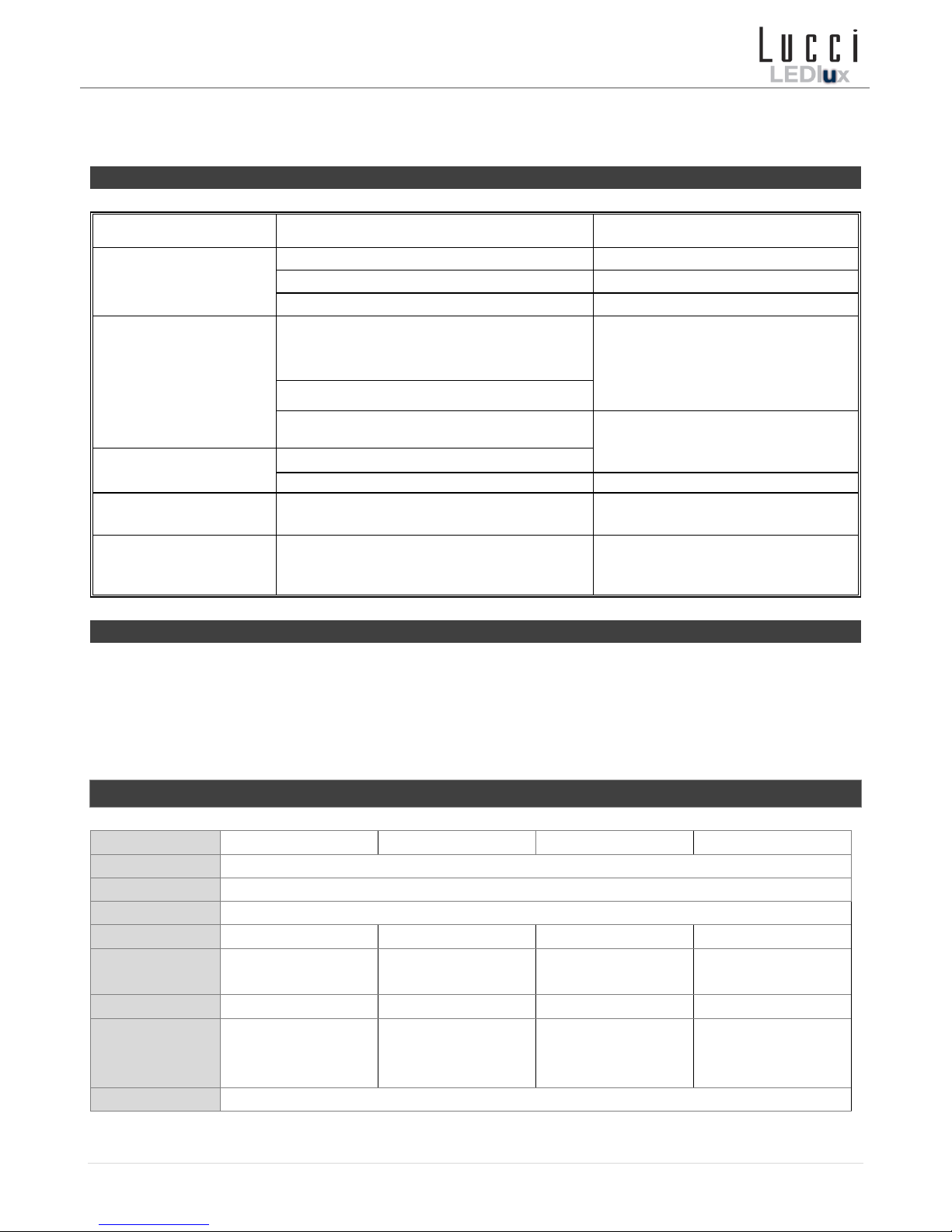
Mains Supply Wire Wiring Label
Earth – Yellow/Green Yellow/Green
Neutral – Blue or Black N (Neutral)
Live – Brown or Red L (Live)
7. Adjust the LED body and PIR sensor to the desired position.
8. Switch the power to circuit back ON only after all electrical work has been fully completed and the fitting is fully
assembled and is ready to use for the first time.
SENSOR SETTINGS:
DURATION TIME: The length of time the light will remain switched on after
activation can be adjusted from 12secs ±5 to 6mins ±2. Rotating the time knob
from (+) to (-) will reduce the duration time.
NOTE: Once the light has been triggered by the PIR sensor, any subsequent
detection will start the timed period again from the beginning, the light will remain
on until there is no movement detected.
ADJUSTING THE SENSITIVITY: The sensitivity means the maximum distance
which PIR Sensor can be triggered by body movement. Turning the SENS knob + to - will decrease the sensitivity.
LUX LEVEL: The lux control module has a built-in sensing device (photocell) that detects daylight and darkness. The
() position means that the fitting will work at both day and night. The () position will only work at night.
NOTE: If you want to test the detection area of the PIR sensor, please wait for the ambient light level is below 5 lux.
SENSOR TESTING:
1. Put the LUX control knob to the light () position and the TIME control knob to minimum (-).
2. Direct the sensor toward the desired area to be scanned by twisting the sensor left and right.
3. Have someone walk across the centre of the area to be scanned and slowly adjust the angle of the sensor until
the fitting can sense the moving person and causes the light to switch on.
4. Adjust the TIME control knob to the desired length of time for the fitting to remain on.
5. Adjust the LUX control knob to achieve the ideal ambient light for the fitting to switch “on”.
For the fitting to switch ‘on’ when the ambient light is darker, switch the LUX control knob from () to ().
For the fitting to switch ‘on’ when the ambient light is brighter, switch the LUX control knob from () to ().

Installation Instructions
4 | P a g e v 1 . 0 p u b l i s h e d o n 0 7 . 2 0 1 7
You may need to make further adjustments to achieve your ideal light level setting.
Note: There is no override function for this fitting.
Trouble shooting
PROBLEM
POSSIBLE CAUSE
SUGGESTED SOLUTION
Light does not switch
on when there is
movement in the
detection area.
No mains voltage.
Check all connections, fuses, switches.
Nearby lighting is too bright.
Redirect sensor or relocate the unit.
Controls set incorrectly.
Readjust sensor angle or control knob.
Light switches on for
no apparent reason
(false trigger)
Heat sources such as air-con, Vents, heater
flues, barbecues, other outside lighting,
moving cars are activating sensor.
Adjust direction of sensor head away
from these sources.
Reflection from a swimming pool or another
reflective surface.
Animals, birds, possums, pets etc.
Redirecting sensor head may help.
Light remains on.
Continuously false triggered.
Time control is set too long.
Reduce time.
Light switches on
during daylight hours.
LUX control knob is set to daylight position.
Turn the LUX control knob to desired
light level setting.
When setting controls
in daylight the detection
distance becomes
shorter.
Interference by sunlight.
Re-test at night.
Safety tips
•Always ensure the power is OFF and the fitting has cooled down before performing any maintenance, cleaning or
making any adjustment to the fitting.
•To avoid injury or damage to the fitting, ensure that power leads and screws are secure before connecting the
power.
•Select a suitable location away from liquids and hazards.
•Ensure that the fitting does not come in contact with corrosive chemicals, etc.
Specifications
SKU #
240711
240713
240715
240717
Colour
Black
Insulation Class
Class I
Rated Voltage
220-240V~ 50Hz
Rated Wattage
10W
20W
30W
50W
LED
BMTC LEDS
4000K, 700lm
BMTC LEDS
4000K, 1400lm
BMTC LEDS
4000K, 2100lm
BMTC LEDS
4000K, 3500lm
Weight
0.45kg
0.78kg
1.0kg
1.25kg
Dimensions
H:275 mm W:135
mm E:170 mm
MAX.
H:310 mm W:181
mm E:185 mm
MAX.
H:330 mm W:217
mm E:200 mm
MAX.
H:355 mm W:237
mm E:210 mm
MAX.
IP Rating
IP44
This manual suits for next models
4
Table of contents
Other LUCCI Floodlight manuals
Popular Floodlight manuals by other brands

American DJ
American DJ Mega GO Bar 50 User instructions

Spotlight
Spotlight Fresnel LED 300 Hyperion user manual

Campbell
Campbell Guardian installation manual

Ayce
Ayce JF01C-P1W5M-BZH65 Operator's manual

KingShield
KingShield LEDFLPIR10E installation instructions

Malibu Boats
Malibu Boats LZ10130 instructions

nox
nox 70-100 quick start guide

Glamox
Glamox FL60 Series operating instructions

Chauvet
Chauvet LED PAR 38-18UVB user manual

Beamz
Beamz Mini Star Ball Sound RGBWA LED 6x3W instruction manual

HUBBELL LIGHTING
HUBBELL LIGHTING Kim Lighting Floodlight installation instructions

Designers Edge
Designers Edge L6004 manual