Lucid Technologies ADA8824 User manual

ADA8824
A/D - D/A Platform
(ADAT Interface)
User’s Guide

TABLE OF CONTENTS
Section 1 Introduction 1
Section 2 Operator Safety Summary 2
Section 3 About the ADA8824 (ADAT) 4
Section 4 Setup (Connections & Settings) 5
Section 5 Product Description
Front Panel Overview 10
Rear Panel Overview 11
Section 6 Using the ADA8824 14
Section 7 Applications & Configurations
Digital Audio Workstation 18
Multitrack Recording 19
A/D-D/A Converter with ADAT Optical I/O 19
A/D-D/A Converter, No ADAT Optical I/O 20
Digital I/O to ADAT Optical I/O 21
Syncing Two Units 22
Section 8 MIDI Implementation Chart 24
Section 9 Block Diagram 25
Section 10 ADA8824 (ADAT) Specifications 26
Section 11 Warranty & Service 28
Section 12 Declaration of Conformity 29
Rev A.0, June 1, 1999
Lucid Technology part number 53ADAT1A00
Specifications subject to change without notice.
©1999 Lucid Technology. All rights reserved.
Lucid is a registered trademark of Symetrix, Inc.
Mention of third-party products is for informational purposes
only and constitutes neither an endorsement nor a recommenda-
tion. Lucid Technology assumes no responsibility with regard to
the performance or use of these products.
Under copyright laws, no part of this manual may be reproduced or
transmitted in any form or by any means, electronic or mechanical,
including photocopying, scanning, recording or by any information
storage and retrieval system, without permission, in writing, from
Lucid Technology.
Lucid Technology
14926 35th Avenue West
Lynnwood, WA 98037 USA
Tel: 425.742.1518
Fax: 425.742.0564
Email: lucid@lucidtechnology.com
Website: www.lucidtechnology.com

1
The Lucid ADA8824 (ADAT) Audio Interface is an eight-channel, 24-bit, A/D and D/A converter
intended for use with digital audio workstations. [For clarity the ADA8824 (ADAT) will be referred
to as the 8824 throughout the rest of this user’s guide.] The 8824 provides ADAT lightpipe connec-
tions, eight analog I/O channels, and eight AES/EBU digital I/O channels.
Designed specifically for Alesis lightpipe (fiber-optic) connections, the 8824 provides a plug and play
audio interface between your studio’s audio gear and the Apple Macintosh or Windows computers.
Created in a strategic partnership with Alesis Corporation, the 8824 delivers the flexibility and
performance you need for leading-edge audio production by providing eight channel digital transfers at
24-bit resolution. Digitally controlled attenuation of analog input and output levels and high-resolu-
tion LED metering help you realize the maximum dynamic range from your digital audio system.
Alesis pioneered the use of fiber-optic connections for digital audio transfer through its proprietary
format. The Alesis PCR card works on Macintosh and Windows computers and is compatible with
products from a wide range of vendors. The growing popularity of ADAT-equipped gear and the
introduction of the 8824 make it even easier for you to stay in the digital domain throughout most of
the production process.
The 8824’s analog I/O channels are equipped with XLR connectors, which accept or deliver either
balanced or unbalanced signals.The AES/EBU digital I/O channels use XLR connectors and the
lightpipe connections use TOSLINK connectors. The 8824 operates at +4dBu, -10dBV, and
intermediate signal levels.
We recommend that you read this manual from cover to cover. Somewhere between the confines of
the two covers you should find the answers to most of your questions, both technical as well as
musical. Please feel free to contact us if you have questions, comments or suggestions.
Phone: 425.742.1518
Fax: 425.742.0564
Email: lucid@lucidtechnology.com
INTRODUCTION SECTION 1
50Hz-60Hz AC INPUT 40 WATTS MAX.
115V
RISK OF FIRE, REPLACE ONLY WITH SAME TYPE FUSE.
CAUTION: FOR CONTINUED PROTECTION AGAINST
ADA8824
ANALOG INPUTS
ANALOG OUTPUTS
OUT
MIDI
INPUT OUT/THRU
AES/EBU DIGITAL INPUTS
INPUTINPUT
OUT/THRU OUTPUT
AES/EBU DIGITAL OUTPUTS
S/P DIF
WORD CLOCK
IN
ADAT OPTICAL
8
8
INPUT OUTPUT
74 5621 3
FOR OPTIONS
6745231
CONFIGURATION
REFER TO USER’S GUIDE
SYNC
ADAT
1
1
2346785
4328765
1-23-45-67-8
5-6 3-4 1-27-8
ANALOG IN
DIGITAL IN
ANALOG OUT
DIGITAL OUT
-1
-3
-9
-15
-12
-6
-1
-3
-1
-3
-9
-15
-12
-9
-15
-12
-6 -6
-21
-27
-24
-30
-50
-40
-21
-27
-24
-21
-27
-24
-30
-50
-40
-30
-50
-40
-18 -18 -18
24-BIT I/O
ADAT OPTICAL INTERFACE
-60 -60 -60
000
-1
-3
-9
-15
-12
-6
-1
-3
-9
-15
-12
-6
-21
-27
-24
-30
-50
-40
-21
-27
-24
-30
-50
-40
-18-18
-1
-3
-1
-3
-9
-15
-12
-9
-6 -6
-12
-15
-21
-27
-24
-30
-50
-40-40
-50
-30
-24
-27
-21
-18 -18
-60-60 -60 -60
48 kHz
44.1 kHz
WORD CLK
AES/EBU
0000
ADA
76853421
TECHNOLOGY
ld
i
cu 8824
METERINGSYNC

2
The lightning flash with arrowhead symbol within an
equilateral triangle is intended to alert the user of the presence
of uninsulated "dangerous voltage" within the product's
enclosure that may be of sufficient magnitude to constitute a
risk of electric shock to persons.
The exclamation point within an equilateral triangle is
intended to alert the user of the presence of important
operating and maintenance (servicing) instructions in the
literature accompanying the product (i.e. this manual).
Caution Topreventelectricshock,donotusethepolarizedplugsuppliedwiththeunitwithanyextensioncord,receptacle,orother
outletunlessthebladescanbefullyinserted.
Terms
Several notational conventions are used in this manual. Some paragraphs may use Note, Caution, or
Warning as a heading or certain typefaces and capitalization are used to identify certain words.These are:
Note Identifies information that needs extra emphasis. A Note generally supplies extra information to help you
to better use the product.
Caution Identifies information that, if not heeded, may cause damage to the Lucid product or other equipment in your system.
Warning Identifies information that, if ignored, may be hazardous to your health or that of others.
CAPITALS Controls, switches or other markings on the product's chassis.
Equipment Markings
OPERATOR SAFETY SUMMARY
AVIS:
NE PAS OUVRIR
Il ne se trouve a l’interieur aucune piece pourvant entre reparée l’usager.
SEE OWNERS MANUAL. VOIR CAHIER D’INSTRUCTIONS.
S’adresser a un reparateur compétent.
RISQUE DE CHOC ELECTRIQUE
N
o user serviceable parts inside. Refer servicing to qualified service personnel
.
CAUTION
WARNING:
TO REDUCE THE RISK OF FIRE OR
ELECTRIC SHOCK DO NOT EXPOSE
THIS EQUIPMENT TO RAIN OR MOISTURE
DO NOT OPEN
RISK OF ELECTRIC SHOCK
Important Safety Instructions
Please read and keep these instructions. Heed and follow all warnings and instructions.
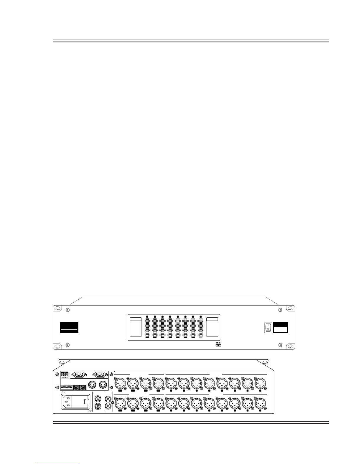
Mains Voltage Selection The Line Voltage selector switch is located near the IEC power inlet
connector. Set it to correspond to the nominal AC mains voltage
used in your studio. The amperage of the fuse changes depending on
the setting of the Line Voltage selector switch. (You must change the
fuse to correspond with the new amperage.)
The fuse ratings are listed later in this section.
Power Source This product is intended to operate from a power source that does
not apply more than 250V rms between the power supply conductors
or between either power supply conductor and ground. A protective
ground connection, by way of the grounding conductor in the power
cord, is essential for safe operation.
Grounding The chassis of this product is grounded through the grounding
conductor of the power cord. To avoid electric shock, plug the power
cord into a properly wired receptacle before making any connections to
SECTION 2

3
the product. A protective ground connection, by way of the grounding
conductor in the power cord, is essential for safe operation. Do not
defeat the safety purpose of the grounding plug. The grounding plug
has two blades and a third grounding prong. The third prong is provided
for your safety. When the provided plug does not fit your outlet, consult
an electrician for replacement of the obsolete outlet.
Danger from If the protective ground connection is lost, all accessible conductive
Loss of Ground parts, including knobs and controls that may appear to be insulated,
can render an electric shock.
Proper Power Cord Use only the power cord and connector specified for the product and
your operating locale. Use only a cord that is in good condition. Protect
the power cord from being walked on or pinched, particularly at plugs,
convenience receptacles, and the point where they exit from the apparatus.
Proper Fuse The user accessible fuse is a part of the IEC AC inlet connector. The
fuseholder accepts 5 x 20mm diameter fuses.
For 117VAC operation, the correct value is 1/2A, 250VAC, slow
blowing (Bussman type GDC-500MA).
For 230VAC operation, the correct value is 1/4A, 250VAC, slow blowing
(Bussman type GDC-250MA).
Operating Location Do not operate this equipment under any of the following conditions:
explosive atmospheres, in wet locations, in inclement weather, improper
or unknown AC mains voltage, or if improperly fused. Do not install
near any heat source such as radiators, heat registers, stoves, or other
apparatus (including amplifiers) that produce heat. Unplug this apparatus
during lightning storms or when unused for long periods of time.
Stay Out of the Box To avoid personal injury (or worse), do not remove the product covers or
panels. Do not operate the product without the covers and panels
properly installed. Only use accessories specified by the manufacturer.
Clean only with a damp cloth.
User-serviceable parts There are no user serviceable parts inside the ADA8824. In case of
failure, refer all servicing to the factory. Servicing is required when the
ADA8824 has been damaged in any way, such as when a power supply
cord or plug is damaged, liquid has been spilled or objects have fallen
into the apparatus, the apparatus has been exposed to rain or moisture,
does not operate normally, or has been dropped.

4
In its principal application, the 8824 connects the external world (analog and digital) of your
studio with your computer using the ADAT lightpipe multichannel interface. In this setup you
will also need a suitable computer (Wintel PC or Apple Macintosh) and a suitable interface card.
Suitable cards are made by Alesis, Sonorus, Korg, Mark of the Unicorn (2408 system),
MIDIMAN and others.
There are many reasons for using an external interface device rather than an all-in-one card that
positions converters inside your computer. Some of these reasons are:
· From an audio signal’s point of view, the inside of your computer is a nasty environment,
both noisy and plagued by RF. Using the 8824 removes the critical steps of A/D and D/A
conversion from this noise-prone box and allows them to take place in an environment
more conducive to high performance, 24-bit conversion.
· Quite often, connecting the computer’s ground system into your audio ground system
causes hum. The lightpipe interface provides complete isolation between the computer’s
ground system and your audio system; each system’s grounding is totally separate and isolated.
· There isn’t nearly enough room on the interface card’s mounting bracket to house suitable
connectors. The rear panel of the 8824 has enough space to house a full complement of
the connectors that you already use in your audio system.
For all of these reasons, we think that the 8824 is the best solution for getting analog and digital
signals into your ADAT lightpipe equipped computer.
Your studio may or may not utilize any Alesis ADAT modular digital multitrack (MDM)
machines. If you use ADAT MDM’s, the 8824 may be used to improve the quality of your audio
conversion and dynamic range. However, you may wish to continue using the machine’s internal
A/D converters rather than the 8824, and your decision will most likely depend on which MDM
you use. The 8824 has no dither capability, so using the 8824 instead of the MDM’s internal
converters may cause audible truncation when using 16-bit MDM’s. Losing these bits won’t cause
the end of the world, or damage to anything, and you might even find the trade-off in dynamic
range to be worthwhile. The degree of truncation you experience will depend on the converter
resolution of your specific MDM.
ABOUT THE ADA8824 (ADAT) SECTION 3

5
SETUP (CONNECTIONS & SETTINGS)SECTION 4
This section discusses a multitude of things, all related to getting signals in and out of the 8824
and getting on with using it.
ADAT Sync Connections
These connectors allow sending and receiving ADAT-specific information between daisy-chained
ADAT machines or other hardware capable of sending or receiving ADAT Sync. The ADAT sync
cable carries machine control, word clock, and timecode signals. These connectors, or the MIDI
connectors, may be used for controlling the 8824. The only signal in the ADAT sync connection
that matters to the 8824 is the machine control signal.
Note If you are using the 8824 with the Alesis PCR card, the 8824 must be the first device
connected after the PCR card. Doing so ensures that the 8824 can always receive
commands (ADAT machines do not always pass ADAT Sync information through
themselves.)
Lightpipe Connections
The lightpipe connectors accept TOSLINK fiber-optic cables. There are two such connectors; one
for input, one for output. The optical signal at these connectors represents all eight channels.
Connect the lightpipe connectors to and from your computer’s lightpipe interface card. There is
no provision within the unit to operate the lightpipe connectors in thru mode.
MIDI Connections
The MIDI connectors receive or send MIDI data. These connectors, or the ADAT Sync
connectors, may be used for controlling the 8824.
Note If you use the MIDI connectors, it is preferable to use a separate MIDI port on your
computer (i.e. one that depends on a different IRQ than the lightpipe interface).
Analog I/O Connections
It is not necessary to connect to any or all of these connectors at any given time. The connectors
used or not used depend on your specific application. In most situations, connect the sources and
destinations that you do have to the 8824. You can then use it as a ‘router’ to patch your sources,
destinations, and the computer workstation software together.
Connect your analog sources to the rear-panel analog input connectors. These connectors may be
driven from a balanced or unbalanced, low-impedance source. When using an unbalanced source,
the preferred connection method is to bring all three input connections through to the unbal-
anced source, tying the shield to the source ground, pin 2/hot to the source hot, and pin3/cold to
the source ground.

6
Connect the analog outputs as required in your studio. These connectors deliver a balanced
output signal from a simulated grounded center-tap source. For unbalanced use, either float pin 3
at the 8824 (preferred), or if necessary, connect it to pin 1 at the 8824.
Digital I/O Connections
It is not necessary to connect to any or all of these connectors at any given time. The connectors
used or not used depends on your specific application. In most situations, connect the sources
and destinations that you do have to the 8824. You can then use it as a ‘router’ to patch your
sources, destinations, and the computer workstation software together.
Connect the AES/EBU input connectors to AES/EBU digital audio sources. Connect the AES/
EBU output connectors to AES/EBU digital audio inputs. If you plan to sync to an AES input,
be sure to use inputs 1-2, 3-4, or 5-6, but not 7-8.
Connect the S/PDIF connectors to consumer audio digital inputs.
Connect the Word Clock input connector to a source of digital audio word clock.
Connect the Word Clock output connector to any other unit requiring the word clock signal.
50Hz-60Hz AC INPUT 40 WATTS MAX.
ADA8824
CONFIGURATION
REFER TO USER’S GUIDE
7 8
7 8
5643
5 643
21
21
FOR OPTIONS
INPUT
TO AES OUTPUT
OF PROFESSIONAL
DAT RECORDER
OF PROFESSIONAL
DAT RECORDER
FROM AES OUTPUT
FROM OUTPUT OF
CONSUMER DAT RECORDER
CD PLAYER OR
S/PDIF IN
INPUT OUTPUT
REMOTE CONTROL
COMPUTER FOR
MIDI OUT FROM
OPTICAL
E
QUIPPED
TO ADAT
I/O CARD
FROM ADAT
EQUIPPED
OPTICAL
I/O CARD
ANALOG AUDIO OUT TO MIXER OR OTHER DESTINATION
ANALOG AUDIO OUT FROM MIXER OR OTHER SOURCE
115V
RISK OF FIRE, REPLACE ONLY WITH SAME TYPE FUSE.
CAUTION: FOR CONTINUED PROTECTION AGAINST
ANALOG INPUTS
ANALOG OUTPUTS
OUT
MIDI
INPUT OUT/THRU
AES/EBU DIGITAL INPUTS
INPUTINPUT
OUT/THRU OUTPUT
AES/EBU DIGITAL OUTPUTS
S/P DIF
WORD CLOCK
IN
ADAT OPTICAL
OUTPUT
SYNC
ADAT
1
1
2346785
4328765
1-23-45-67-8
5-6 3-4 1-27-8
Figure 3-1. Computer Connections

7
Table 1. Dip Switch Settings in Local mode (SW1 up at power-up).
Table 2. Clock Selector Switch Settings
cnyStupnInoitisoPwSpiD
ecruoS)2WS(0leSklC)3WS(1leSklC)4WS(2leSklC
lacitpOTADA NWODNWODNWOD
tupnIkcolCdroW PUNWODNWOD
kcolczHk1.44lanretnI NWODPUNWOD
kcolczHk84lanretnI PUPUNWOD
1tupnISEA NWODNWODPU
2tupnISEA PUNWODPU
3tupnISEA NWODPUPU
tupnIFIDP/S PUPUPU
Configuration Settings
The rear-panel configuration switches determine the initial conditions (power-up) of the 8824.
For most applications use Remote mode (set SW1 down). Set SW2 thru SW4 as required by the
input selection and clock source. Refer to Table 2.
SW5-8 have different functions depending on the mode selection (SW1). In Local mode, these
switches determine the origins of the various output signals and the monitoring point for the
meters. Refer to Table 1. In Remote mode, the arithmetic sum of the bit values of these switches
(SW5-7) sets the MIDI device number (0-7). SW8 switches the MIDI command input between
the ADAT Sync input and the DIN-5 MIDI input connectors. Refer to Table 3.
1WS2WS3WS4WS5WS6WS7WS8WS
/lacoL
etomeR 0leSklC1leSklC2leSklC
golanA
tuptuO
ecruoS
UBE/SEA
tuptuO
ecruoS
lacitpO
tuptuO
ecruoS
tceleSreteM
PU lacoL eeS
2elbaT SEAgolanASEAtuptuO
NWOD etomeRTADATADAgolanAtupnI
1WS2WS3WS4WS5WS6WS7WS8WS
/lacoL
etomeR A/NA/NA/N0eciveD1eciveD2eciveD tupnIIDIM
tceleS
PU lacoL
A/N
eeS cnySTADA
)tupnI(
NWOD etomeR4elbaTIDIM
Table 3. Dip Switch Settings in Remote mode
(SW1 down at power-up).
eciveD
5WS6WS7WS
DI
0eciveD1eciveD2eciveD
0
NWODNWODNWOD
1
PUNWODNWOD
2
NWODPUNWOD
3
PUPUNWOD
4
NWODNWODPU
5
PUNWODPU
6
NWODPUPU
7
PUPUPU
Table 4. Device ID selection.

8
The 8824 Configuration Application
Included with the 8824 is a small application that implements a virtual front panel so you can
alter the settings of the unit. If you have any familiarity with Windows or Macintosh applica-
tions, you’ll be right at home.
Installation
On either Wintel or Macintosh platforms, make a separate folder and copy the appropriate file
into that folder. On your desktop, create a shortcut to the configuration application that you just
copied into the folder. Double-click on the shortcut to launch the application.
Settings
Unit Number Dropdown menu selects unit number (0-7).
Analog Output Source Select either ADAT or AES. The eight analog outputs are generated
from this source.
AES Output Source Select either ADAT or Analog (input). The four AES/EBU output
pairs are generated from this source.
Optical Output Source Select either Analog or AES. The lightpipe signal is generated from
this source. There are four of these switch blocks; one for channels
1-2, 3-4, 5-6, 7-8.
A/D Sync Source Select from the following: ADAT, Word Clock, Internal 44.1kHz,
internal 48kHz, AES 1-2, AES 3-4, AES 5-6, S/PDIF. The 8824
locks its clock to the selected source. The front panel indicator
relays this information. If ADAT is the sync source, then none of
the front panel sync indicators illuminate. If the A/D sync source
does not match a valid clock source, or if the optical outputs are
fed by a mixture of analog and AES inputs AND the A/D sync
source is not set to the appropriate AES input, audible distortion
may occur.
Digital Input 1,2 Select Select either AES or S/PDIF. Digital inputs 1-2 can use either the
AES/EBU digital inputs (XLR) or the S/PDIF digital inputs (RCA/Coax).
Meters Select from Analog Inputs (ADC), Digital Inputs (AES), Analog
Outputs (DAC) or Digital Outputs (AES).
Apply button Sends all settings to the 8824.
Quit button Quits the configuration application without making any changes.
Save and Quit Saves the changes made and quits the application.
File Menu
Print Screen Prints the current screen display.
Print Setup Modifies the current printer setup.
Exit Exits the configuration application.

9
MIDI Setup
MIDI In Port Select the MIDI In port via the dropdown menu. You must have
preconfigured the MIDI device via the Control Panel.
MIDI Out Port Select the MIDI Out port via the dropdown menu. You must have
preconfigured the MIDI device via the Control Panel.
I/O Setup
Input Gain Displays the Analog Input Gain Control dialog box. Eight virtual faders
determine the input gain setting ahead of the A/D converters. Two push
buttons set all inputs for +4dBu or -10dBV input levels.
Refer to the discussion on this topic below.
Output Gain Displays the Analog Output Gain Control dialog box. Eight virtual faders
determine the output gain setting after the D/A converters. Two push
buttons set all outputs for +4dBu or -10dBV signal levels.
Refer to the discussion on this topic below.
Digital Output Displays the Digital Output Channel Status dialog box. Select between
Configuration AES and S/PDIF output format and the sample rate for the digital output.
Help
About Version and copyright information for this application.
Gain and Headroom
The two gain control screens display virtual faders that adjust the amount of gain or attenuation
applied to input or output signals. Two push buttons allow presetting the gain to accommodate
nominal +4dBu or –10dBV signals. At 0dB of gain, an input signal of –4dBu corresponds to a reading
of 0dBFS as read on the 8824’s meter. These readings are based on the use of sinewaves. The same gain
relationship applies at the output side of the 8824.
At the input side, the +4dBu button sets the input gain to –8dB, which translates to approximately
20dB of digital headroom (20dB below 0dBFS). Remember that the +4dBu number represents a
signal level read on an average responding indicator (i.e. VU meter), and the metering in the 8824
responds to peaks. If the +4dBu signal has a 20dB peak to average ratio, then this means that the signal
peaks correspond to +24dBu. If the program material allows, either due to your mixing style, com-
pression or limiting, or just the material itself, you may wish to reduce the amount of headroom to
place the signal as high as possible within the converter’s dynamic range window. Likewise, for espe-
cially dynamic signals, you may want to increase the amount of headroom allowed for these signals.
For –10dBV signals, the –10dBV button sets the input gain to +4dB, which again translates to
approximately 20 dB of dynamic range. The numbers may seem to be off until you recall that a
–10dBV signal is the same as a –7.8dBu signal (1V = 0dBV and 1V = +2.2dBu).
For both input and output, there is up to 31dB of gain or 95dB of attenuation available.
Note The balanced line receiver can accept signals up to +25dBu.This is independent of any input
attenuation setting.

10
PRODUCT DESCRIPTION - FRONT PANEL OVERVIEW SECTION 5
SYNC Window
Displays the source of digital audio sync: 44.1kHz internal, 48kHz internal, Word
Clock, or AES/EBU digital input (inputs 1-2, 3-4, 5-6, or S/PDIF). If ADAT sync is
selected the display will be unlit.
ANALOG IN
DIGITAL IN
ANALOG OUT
DIGITAL OUT
-1
-3
-9
-15
-12
-6
-1
-3
-1
-3
-9
-15
-12
-9
-15
-12
-6 -6
-21
-27
-24
-30
-50
-40
-21
-27
-24
-21
-27
-24
-30
-50
-40
-30
-50
-40
-18 -18 -18
24-BIT I/O
ADAT OPTICAL INTERFACE
-60 -60 -60
000
-1
-3
-9
-15
-12
-6
-1
-3
-9
-15
-12
-6
-21
-27
-24
-30
-50
-40
-21
-27
-24
-30
-50
-40
-18-18
-1
-3
-1
-3
-9
-15
-12
-9
-6 -6
-12
-15
-21
-27
-24
-30
-50
-40-40
-50
-30
-24
-27
-21
-18 -18
-60-60 -60 -60
48 kHz
44.1 kHz
WORD CLK
AES/EBU
0000
ADA
76853421
TECHNOLOGY
l
d
i
cu
8824
METERINGSYNC
48 kHz
44.1 kHz
WORD CLK
AES/EBU
1
SYNC
LED Meters
15-segment LED bargraph meters display digital or analog
signal levels from either input or output. The source and
mode selections are made via software from the host
computer. The rear panel switches determine the source
and mode when there is no host computer.
-1
-3
-9
-15
-12
-6
-1
-3
-1
-3
-9
-15
-12
-9
-15
-12
-6 -6
-21
-27
-24
-30
-50
-40
-21
-27
-24
-21
-27
-24
-30
-50
-40
-30
-50
-40
-18 -18 -18
-60 -60 -60
000
-1
-3
-9
-15
-12
-6
-1
-3
-9
-15
-12
-6
-21
-27
-24
-30
-50
-40
-21
-27
-24
-30
-50
-40
-18-18
-1
-3
-1
-3
-9
-15
-12
-9
-6 -6
-12
-15
-21
-27
-24
-30
-50
-40-40
-50
-30
-24
-27
-21
-18 -18
-60-60 -60 -60
0000
76853421
Metering Window
Displays the source and mode of the meters: Analog Input, Digital Input, Analog
Output, Digital Output.
ANALOG IN
DIGITAL IN
ANALOG OUT
DIGITAL OUT
8
METERING
ADA
8824
Power Switch
Turns the unit on.
|= On
O = Off

11
PRODUCT DESCRIPTION - REAR PANEL OVERVIEW
ADAT Sync connectors
Two DB-9 female connectors. These connectors accept and deliver
ADAT Sync signals. ADAT Sync consists of three signals: machine
control, ADAT word clock and time code. Include the ADA8824
(ADAT) first in the chain of ADAT sync devices.
Configuration Switches
DIP switch. This switch has six functions: local/remote operation, input sync
source, analog and digital output (AES/EBU and optical) source, and meter
source select. This switch is read at initialization (power-on). The remaining
switches are meaningless when a remote computer is used.
The local/remote switch allows operation without the use of a separate com-
puter. The UP position is local operation (no computer), DOWN is remote.
This might be useful in a stand-alone situation, or if your computer crashes.
The analog output source switch determines whether the source for the analog output will be the
signal at the AES/EBU output of the ADAT output. UP is AES, DOWN is ADAT.
The AES/EBU output source switch determines whether the source for the AES/EBU digital
output is the signal at the analog outputs or the ADAT outputs. UP is analog, Down is ADAT.
The optical output source switch determines whether the source for the optical output is the
AES/EBU or analog output signals. UP is AES, DOWN is analog.
The meter source select switch determines whether the default meter signal source is the output
(up) or input (down).
Note Refer to discussion of dip switch settings and tables on page 7.
ADAT Optical connectors
TOSLINK optical (fiber-optic) connectors accept or deliver ADAT optical
signals. The ADAT Optical signal is a multitrack 24-bit digital audio intercon-
nectionstandard.
50Hz-60Hz AC INPUT 40 WATTS MAX.
115V
RISK OF FIRE, REPLACE ONLY WITH SAME TYPE FUSE.
CAUTION: FOR CONTINUED PROTECTION AGAINST
ADA8824
ANALOG INPUTS
ANALOG OUTPUTS
OUT
MIDI
INPUT OUT/THRU
AES/EBU DIGITAL INPUTS
INPUTINPUT
OUT/THRU OUTPUT
AES/EBU DIGITAL OUTPUTS
S/P DIF
WORD CLOCK
IN
ADAT OPTICAL
8
8
INPUT OUTPUT
74 5621 3
FOR OPTIONS
6745231
CONFIGURATION
REFER TO USER’S GUIDE
SYNC
ADAT
1
1
2346785
4328765
1-23-45-67-8
5-6 3-4 1-27-8
50Hz-60Hz AC IN
P
4
AD
A
8
8
INP
U
74 5621 3
FOR OPTIONS
6745231
CONFIGURATION
REFER TO USER’S GUIDE
OUT
MIDI
IN
ADAT OPTICAL
8
8
INPUT OUTPUT
7
5
6
TIONS
675
U
RATION
S
ER’S GUIDE
SYNC
ADAT
Hz-60Hz AC INPUT 40 WATTS MAX.
OU
INPUT
W
IN
ADAT OPTICAL
8
8
INPUT OUTPUT
756
P
TIONS
675
U
RATION
S
ER’S GUIDE

12
MIDI Input and Output
5-pin female DIN connectors accept or deliver MIDI signals.The ADA8824
(ADAT) uses MIDI for control when not being operated in stand-alone or ADAT
Sync modes. The ADA8824 (ADAT) uses Sysex commands for control.
AES/EBU Inputs
XLR-3 female connector. This connector accepts digital audio
signals using the AES-3 protocol (which includes older AES/EBU
signals).The connectors are paired (marked 1-2, 3-4, etc.) because
each AES-3 signal represents two digital audio channels.
Inputs 1-2, 3-4, or 5-6 are also used for external AES/EBU sync
inputs.
ANALOG INPUTS
XLR-3 female connector. This
connector accepts analog audio
signals from balanced or unbal-
anced sources.The input imped-
ance is 20-kilohms, balanced
(diff-amp input). The maxi-
mum input level is +25 dBu. This connector should be driven from a low source impedance.
Analog Outputs
XLR-3 male connector. This
connector delivers balanced audio
signals from a 320-ohms source.
The output stage emulates a
grounded center-tap transformer.
The maximum output level is
+25 dBu For unbalanced loads, either float the unused output pin (usually pin 3), or ground it at the
ADA8824 (ADAT). Floating pin 3 is the preferred method.
AES/EBU OUTPUTS
XLR-3 male connector. This connector delivers digital audio
signals using the AES/EBU.The connectors are paired (marked 1-
2, 3-4, etc.) because each AES/EBU signal represents two digital
audio channels.
ANALOG INPUTS
12346785
ANALOG OUTPUTS
14328765
AES/EBU DIGITAL INPUTS
1-23-45-67-8
A
TTS MAX.
OUT
MIDI
INPUT OUT/THRU
S/P DI
F
WORD CLOCK
IN
A
L
U
T
AES/EBU DIGITAL OUTPUTS
5-6 3-4 1-27-8

13
50Hz-60Hz AC INPUT 40 WATTS MAX.
115V
RISK OF FIRE, REPLACE ONLY WITH SAME TYPE FUSE.
CAUTION: FOR CONTINUED PROTECTION AGAINST
ADA8824
INPUT
IN
OU
T
WOR
D
86745231
S/PDIF INPUT AND OUTPUT
RCA female connectors.These connectors accept or deliver S/PDIF digital audio signals.
The S/PDIF input can also be used as an external sync source.
OUT/THRU
INPUTT
H
RU OUTPUT
S/P DIF
LOCK
M
AX.
INPUT OUT/THR
U
INPUT
OUT/THRU
WORD CLOCK
WORD CLOCK INPUT and OUTPUT/THROUGH
BNC male connectors. These connectors accept or deliver word clock signals. Word
clock is another method of synchronizing multiple digital audio signals. The word clock
output is synchronized to the AES/EBU digital outputs. If the AES/EBU outputs are
fed from the analog inputs, the word clock output gets its signal from the A/D sync
source. If the AES/EBU outputs are fed from the ADAT optical input, the word clock
output gets its signal from that input.
AC Power Input, Voltage Selector, and Fuse
IEC-power connector. Connect only to appropriate AC power source.
Refer to rear-panel marking for correct AC source value.
The Line Voltage selector switch determines the proper AC mains
voltage required for operation. Set this switch to correspond with the
nominal AC mains voltage used in your studio.
The user accessible fuse is a part of the IEC AC inlet connector. The
fuseholder accepts 5 x 20mm diameter fuses.
For 117VAC operation, the correct value is 1/2A, 250VAC, slow
blowing (Bussman type GDC-500MA).
For 230VAC operation, the correct value is 1/4A, 250VAC, slow
blowing (Bussman type GDC-250MA).

14
USING THE 8824 SECTION 6
Overview
This section of the manual discusses some technical issues that you’ll need to be familiar with and a
few applications scenarios. This information may be useful if you want to get everything you can from
the 8824.
Now that you’re familiar with the 8824, use the Fast Setup section of this manual to integrate the unit
into your studio. If you’re using the unit without a host computer, be sure to set the configuration
switches located at the rear of the unit.
Level Setting
Like any A/D converter, the converter’s output represents a fixed window that must properly frame the
audio signal. Set it too low, and lose the signal peaks; set it too high and lose the low-level detail.
In the 16-bit world, when that was all there was for conversion, the placement of the converter win-
dow was more critical due to the larger step size represented by each bit of the digital output. The low
level details in the signal represent things like ambience and soundstage; thus they are critical details.
Capturing these details faithfully means becoming more adept at either setting the window properly or
fitting the signal into the window itself via dynamic range compression.
A 24-bit converter eases this task somewhat. Since the steps are smaller, you now have the option of placing
the audio signal either a bit higher (better resolution for low-level signals, but lower headroom) or lower
(less resolution for low levels, but higher headroom). Of course, if the signal is already recorded, then it’s just
a matter of getting levels set properly and then making the transfer into your workstation.
It’s conceivable that you might want to make a 24-bit recording directly into your workstation. In this
case, set your levels carefully and/or use some preprocessing in the analog domain to make the audio
signal fit into the conversion window.
Clock and Sync Issues
Any time that you have multiple digital audio signals at one time the issue of sync becomes important. Sync
between the signals is important because the converters in the 8824 share a common clock; therefore
external digital signals need to arrive in-sync. This is not a problem if the signals come from a digital multi-
track, however it may be a problem if the signals come from separate sources. In this case, you may need to
provide a sync signal for each of these devices.
It is also possible to sync the 8824’s converters to an external source. You can sync to an external AES/EBU
signal via the 1-2 Digital Inputs or to the Word Clock input. Source selection occurs at the 8824 configura-
tion application. The 8824 does not use the ADAT word clock signal in the ADAT sync connector.
However, it can sync to ADAT signals delivered via the lightpipe connectors.
Note The word clock output is synchronized to the AES/EBU digital outputs. If the AES/EBU
outputs are fed from the analog inputs, the word clock output gets its signal from the A/D
sync source. If the AES/EBU outputs are fed from the ADAT optical input, the word clock
output gets its signal from that input.

15
MIDI Implementation
MIDI control is performed by using either the standard MIDI connectors, OR by using the ADAT
Sync connectors.The ADAT Sync connectors are not used for any other purpose, with the exception
of allowing ADAT specific information to be daisy-chained to multiple ADATs. To switch between
MIDI or ADAT Sync connectors, see below, under switch configuration.
All MIDI control of the 8824 is performed by MIDI Sysex commands. This sequence is composed of
the Sysex start byte (F0) followed by the Lucid Manufacturer ID (00 00 5E), followed by the 8824’s
ID (58 hex = 88 decimal), and the particular command and data. The structure of each Sysex is as
follows (all bytes in hexadecimal):
F0 00 00 5E 58 x y <z1z2.. zn> F7
where x is the 8824’s specific device number (0 to 7),
y is the command code, and
z1through znis the data associated with the command (the length varies depending on the
command)
Command information:
Set Mode : F0 00 00 5E 58 x 20 z F7
where z is defined as follows:
Bit 0 : Analog/Digital Meter Select (0 = analog; 1 = digital)
Bit 1 : Input/Output Meter Select (0 = input; 1 = output)
Bit 2 : Digital Input 1 Selector (0 = AES; 1 = S/PDIF)
Set Sync : F0 00 00 5E 58 x 21 z F7
where z is a 3-bit field (ClkSel0::2), defined as follows:
Set Optical Output Source : F0 00 00 5E 58 x 22 z F7
where z = 0 selects analog inputs; z = 1 selects AES inputs
Set Analog Output Source : F0 00 00 5E 58 x 23 z F7
where z = 0 selects ADAT optical input; z = 1 selects AES inputs
cnyStupnIdleiFtiBeerhT
ecruoS0leSklC1leSklC2leSklC
lacitpOTADA 000
tupnIkcolCdroW 100
kcolczHk1.44lanretnI 010
kcolczHk84lanretnI 110
1tupnISEA 001
2tupnISEA 101
3tupnISEA 011
tupnIFIDP/S 111

16
Set AES Output Source : F0 00 00 5E 58 x 24 z F7
where z = 0 selects ADAT optical input; z = 1 selects analog inputs
Set Analog I/O Gain : F0 00 00 5E 58 x 30 z1z2.. z16 F7
where z1through z16 is the analog gain/attenuation for each analog I/O channel, ordered with inputs
first, then outputs, and reverse ordered from channels 8 through 1 for both inputs and outputs.
The gain value is a 7-bit number (from 0 to 7F) which provides gain control in 1dB increments from
-95dB to +31dB.
With the
input
gain set to -8dB (hex 58), a +4dBu input translates to approximately -20dbFS (i.e.
20dB digital headroom).With the
input
gain set to +4dB (hex 64), a -10dBV input translates to
approximately -20dbFS (again, 20dB of digital headroom).
Similarly, with the
output
gain set to +1dB (hex 61), a -20dBFS input translates to approximately
+4dBu into 600ohms.With the
output
gain set to -11dB (hex 55), a -20dBFS input translates to
approximately -10dBV. In both of these cases, the actual headroom before clipping depends on the
inputs of the mixer, power amplifier, etc, that the 8824 is driving.
Set digital output control : F0 00 00 5E 58 x 40 z1 z2 F7
where z1 is the address in the digital output buffer to write, and z2 is the encoded data to write.
For this command, there are 2 areas of control. Firstly, the digital outputs must be initialized by
sending:
F0 00 00 5E 58 x 40 03 08 F7
F0 00 00 5E 58 x 40 02 03 F7
F0 00 00 5E 58 x 40 23 08 F7
F0 00 00 5E 58 x 40 22 03 F7
F0 00 00 5E 58 x 40 43 08 F7
F0 00 00 5E 58 x 40 42 03 F7
F0 00 00 5E 58 x 40 63 08 F7
F0 00 00 5E 58 x 40 62 03 F7
Then, the channel status bits may need to be set, depending on what digital equipment you are
transmitting to.There are 8 addresses of interest to set, 2 for each output channel (each channel
is offset by 20 hex bytes).The table on the next page summarizes the addresses and data for
common setups. Formats can be mixed on a per channel basis.
All data is shown in hexadecimal.

17
Professional Mode Consumer Mode
Address 32k 44.1k 48k N.I.*32k 44.1k 48k
08 31 11 21 01 00 00 00
0B 00 00 00 00 03 00 02
28 31 11 21 01 00 00 00
2B 00 00 00 00 03 00 02
48 31 11 21 01 00 00 00
4B 00 00 00 00 03 00 02
68 31 11 21 01 00 00 00
6B 00 00 00 00 03 00 02
* Not indicated
The 8824’s MIDI implementation table may be found in Section 8 of this manual.

18
Applications
It is impossible to anticipate exactly how you’ll use the ADA8824 (ADAT) in your studio, but
we can make a few educated guesses.
Digital Audio Workstation
In this application, the 8824 may find itself used alone or with accompanying ADAT machines.
The 8824 becomes the computer’s link to the analog and digital world. Since the unit performs
routing functions in addition to analog and digital conversion, it is a convenient way to route and
deliver digital and analog signals to and from your workstation.
In conjunction with most DAW applications, such as Cakewalk Pro Audio, the 8824’s configura-
tion application determines the ‘front panel’ settings of the unit. For analog sources, the 8824
converts these signals into 24-bit digital audio, and routes them to the computer via the lightpipe
interface. On the return trip, the 8824 can route signals to the S/PDIF connectors, to any of the
AES/EBU digital outputs, or to the analog outputs. For digital sources, the 8824 bundles them
into the 8-channel ADAT lightpipe format and ships them off to the computer. Returning from
the computer, the 8824 can deliver signals as AES/EBU digital signal pairs, analog audio, or S/
PDIF signals.
If you are mixing to DAT or for CD release, be sure that your workstation software has been set
to reduce the 24-bit signals to 16-bit and to perform dithering. The 8824 has no facilities for
dithering its output signal.
Note: You can not record 24-bit signals onto a DAT recorder unless your DAT machine is one
that has 24-bit recording capability. The DAT format is 16-bit by design. Trying to record longer
word lengths onto a DAT simply results in losing the extra bits (truncation). The resulting tape
will play, but the audio, particularly at the lowest levels, will suffer.
On the Wintel platform, it is easier to use the 8824 if you use a separate MIDI interface card
rather than that provided (if any) on your lightpipe interface card. A Windows 95/98 limitation
prevents one MIDI port from being used by more than one application. This limitation requires
you to open the configuration application alone, make your configuration adjustments, close the
configuration application, and then start your DAW application. Making any changes later re-
quires closing the DAW application first, reopening the configuration application, making the
configuration changes, etc. Not impossible, but certainly tedious. Having a physically separate
MIDI interface allows the configuration application to remain open while running your DAW
application.
When using any ADAT MDM machines and transferring data into your workstation, you’ll need
to disconnect the 8824’s output (lightpipe) connection so that you can move it to the ADAT
machine. The 8824’s ADAT lightpipe connections have no provision for thru operation. Of
course, if your lightpipe interface card has multiple lightpipe I/O connections (highly recom-
mended), then you can leave the MDM’s connected all the time and make the switch in software.
APPLICATIONS & CONFIGURATIONS SECTION 7
Table of contents
Popular Media Converter manuals by other brands

Lacon
Lacon L-EMM100CO manual

Monico
Monico CDL Installation and operation guide

TR-Electronic
TR-Electronic CRW582M 8192 CO+CO SLG ME 5M Series Assembly instructions

Dutec
Dutec BaudMaster BMUSB user manual

Leader Electronics Corp.
Leader Electronics Corp. LT 443D instruction manual

Iluminarc
Iluminarc LOGIC POE X Quick reference guide