Lucoro Broadcast TX-FMBR1 User manual

TX-FMBR1
FM Broadcast Repeater with
audio (MPX) and RDS back-up
Index
IMPORTANT!
Do not misconstrue any Information as our recommendation to use any
product, process, or equipment in conflict with any regulatory authority or
patent. NO REPRESENTATIONS OR WARRANTIES, EITHER EXPRESS OR
IMPLIED, OF MERCHANTABILITY, FITNESS FOR A PARTICULAR PURPOSE
OR OF ANY OTHER NATURE ARE MADE WITH RESPECT TO ANY
PRODUCT.
Ensure compliance with all applicable safety requirements when installing or
using this equipment, and operate in accordance with local laws governing
the use of radio transmission equipment.
Technical Manual

Lucoro Broadcast TX-FMBR1 Technical Manual
Page 1
1. Introduction
1.1 General 3
2. Safety information
2.1 General Safety Information 4
2.2 Before Operating this unit 5
3. Controls and Connectors
3.1 Front Panel Controls and Connectors 6
3.2 Rear Panel Connectors 6
3.3 Display 9
4. Installation
4.1 Connections 10
4.2 Switching On 10
4.3 Operation 10
4.4 Settings 11
4.5 Co-channel Operation 11
5. Internal Adjustments
5.1 Transmitter Carrier Frequency Trim 12
5.2 External Audio MPX Input Modulation Level 12
5.3 Internal RDS Encoder Injection Level 12
5.4 Receiver Modulation Level 12
5.5 Updating RDS Content 12
6. RS485
6.1 Protocol 14
6.2 Message Structure 14
6.3 CRC (Cyclic Redundancy Check) 15
6.4 Read Commands 15
6.5 Write Commands 15
6.6 Command Descriptions 16
7. RS485 Communications Examples 21
8. Declaration of Conformity 23
9. Technical Specification 24

Lucoro Broadcast TX-FMBR1 Technical Manual
Page 2
Disclaimer
While every effort is made to make sure the information is accurate and up-to-date,
we do not accept any liability for any direct, indirect, or consequential loss or damage
of any nature - however caused - which may be sustained as a result of reliance
upon such information.
No part of this document may be reproduced or transmitted, in any form, by any
means, without prior written consent of the Lucoro Broadcast in the UK.
Lucoro Broadcast shall not be liable for any direct, indirect, incidental, consequential
or other damage or loss alleged in connection with the supply or use of this product.
The information contained in this document is subject to change without notice.
Lucoro Broadcast makes no warranty of any kind with respect to this information.
Lucoro Broadcast specifically disclaims the implied warranty of merchantability and
fitness for a particular purpose.
Lucoro Broadcast shall not be liable for any direct, indirect, incidental, consequential
or other damage or loss alleged in connection with the furnishing or use of this
information.

Lucoro Broadcast TX-FMBR1 Technical Manual
Page 3
1. Introduction
1.1 General
The TX-FMBR1 is a 2W VHF FM Broadcast Exciter Transmitter with integral 87.5-
108MHz PLL MPX Broadcast Receiver. An external MPX input is available to allow
for back-up during parent signal loss, plus an integral RDS encoder is fitted.
The unit features Analogue to Digital measurement technology, with menu driven
LCD screens for monitoring and adjustments.
At the heart of the TX-FMBR1 is a broadcast quality exciter. Carrier frequency and
output power is selectable via the front panel LCD menu. The output includes an
efficient amplifier stage and RF filter.
The integral PLL receiver has a sensitive Front End and high performance IF section.
ensuring a high quality MPX signal is recovered with low Signal to Noise levels, thus
providing an accurate rebroadcast of the parent station.
The unit can be controlled directly using the simple rear interface to control audio
break-in and muting and to provide basic telemetry alarm functions.
A more comprehensive remote control interface uses a simple two wire RS485 data
scheme. The unit can be part of system containing up to 32 other units. Each TX-
FMBR1 can be assigned an address allowing independent or group control. The user
can select the unit’s address using the front panel LCD menu controls.
The TX-FMBR1 is designed to operate continually for many years without
maintenance. There are no cooling fans to replace and the carefully specified, quality
components ensure ultimate reliability.

Lucoro Broadcast TX-FMBR1 Technical Manual
Page 4
2. Safety Information
2.1 General Safety Information
Use of this device into a radiating antenna requires a valid licence from a Spectrum
Management Authority in most countries.
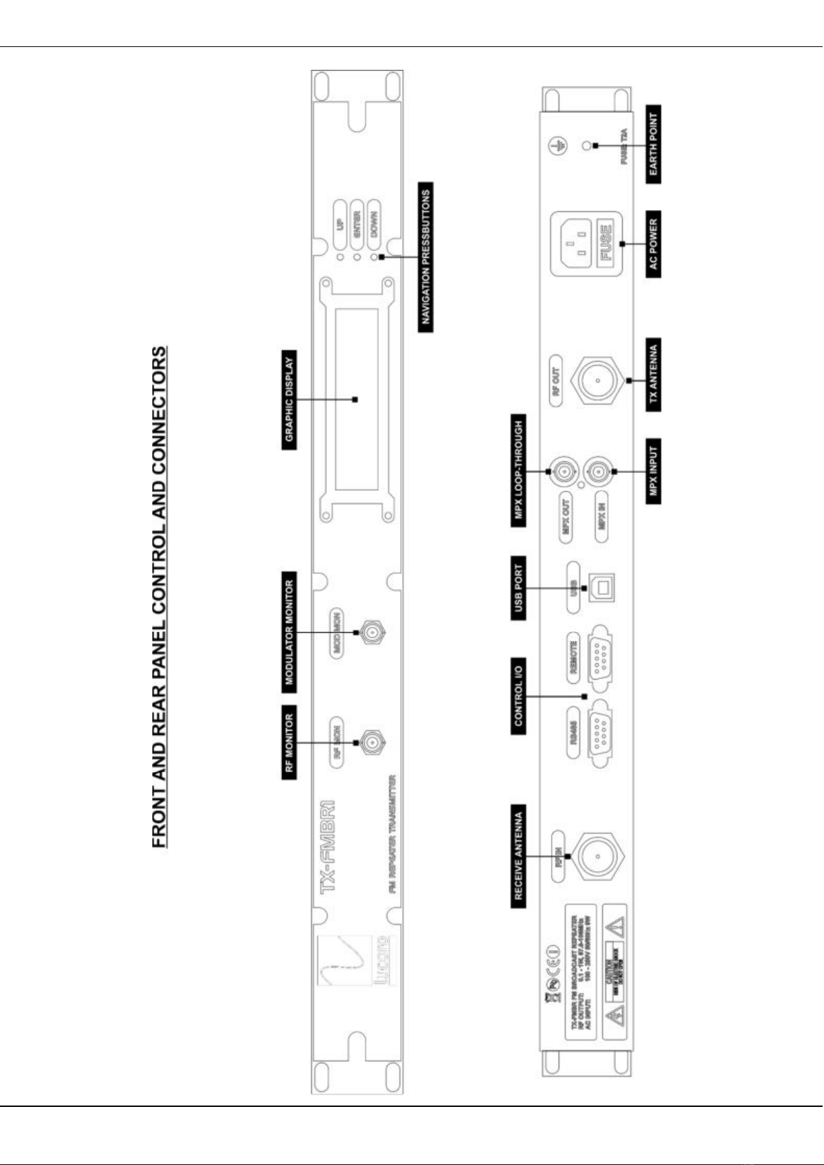
Never operate this device without a suitable 50 ohm load connected to the RF
OUTPUT socket, or without a suitable antenna. Although the output of this
transmitter is protected against antenna mismatches, MIS-OPERATION MAY
RESULT IN DAMAGE NOT COVERED BY ANY WARRANTY.
Use of this device as part of a transmission system, or combined transmission
system not specified by the manufacturer, may require further testing to ensure that it
remains compliant with the essential requirements and other relevant provisions of
current EU Low Voltage, EMC and Radio Equipment Directives. Approval and
clearance from the Spectrum Management Authority may also be required.
RISK OF FIRE! RF (Radio Frequency) energy could cause ignition of combustible
surfaces during fault conditions. Installation should be left to qualified personnel. RF
can cause burns to skin. Ensure antenna systems and feeder cables are not situated
near – or could fall onto – any combustible surface.
Installation must adhere to safety regulations and the requirements of the relevant
authorities. We recommend that at least two people are present during installation.
Keep a file containing installation instructions and plans, including details of the
transmission system (antennas, feeders, filters, etc) and operating instructions for all
equipment at the transmission site at all times. Display posters detailing first aid
treatment and treatment for electrical shock, along with telephone numbers for
contacting the emergency services in the event of personal injury.
To reduce the risk of electrical shock, do not remove the cover, or any screws. There
are no user serviceable parts inside; refer servicing to qualified personnel.
To reduce the risk of fire or electrical shock, do not expose this appliance to rain or
moisture.
To reduce the risk of fire, always replace fuses with the same type and rating.
Do not operate this appliance without a suitable 50 ohm load or a suitably matched
antenna connected to the RF OUTPUT socket. Although the output devices used in
this transmitter are intended to be open and short circuit tolerant, MIS-OPERATION
MAY RESULT IN DAMAGE NOT COVERED BY ANY WARRANTY.
This appliance may become warm under normal operating conditions.

Lucoro Broadcast TX-FMBR1 Technical Manual
Page 5
2.2 Before Operating This Unit
These instructions should be read in full before the transmitter is operated.
The safety and operating instructions should be retained for future reference.
All warnings on the transmitter and in the operating instructions should be adhered
to.
All operation and user instructions should be followed.
The transmitter should not be used near water.
The transmitter should be mounted into a well-ventilated standard 19 inch equipment
rack. It should be situated so that its location or position does not interfere with its
proper ventilation.
The transmitter should be situated away from heat sources.
The transmitter should be connected to a power supply only of the type described in
the operating instructions or as marked on the unit.
Precautions should be taken so that the grounding or polarisation means of this
appliance is not defeated.
Power supply cords should be routed so that they are not likely to be walked on, or
pinched by items placed upon or against them, paying particular attention to cords
and plugs and the point where they exit from the transmitter.
The unit should be cleaned only as recommended by the manufacturer.
The power cord of the transmitter should be unplugged from the outlet when left
unused for a long period of time.
Care should be taken so that objects do not fall and liquids are not spilled into the
enclosure through openings.
The transmitter should be serviced by qualified service personnel when: - The power
supply cord or the plug has been damaged; or - Objects have fallen, or liquid has
been spilled into it; or - The transmitter has been exposed to rain; or - The transmitter
does not appear to operate normally or exhibits a marked change in performance; or
- The transmitter has been dropped, or the enclosure damaged.
The user should not attempt to service the transmitter beyond that which is described
in the Operating Instructions. All other servicing should be referred to qualified
service personnel.

Lucoro Broadcast TX-FMBR1 Technical Manual
Page 6
3. Controls & Connections
3.1 Front Panel Controls and Connectors
RF (Radio Frequency) Monitor BNC. Allows monitoring of the RF output. Output level
will be the output power attenuated by approximately 50dB.
AF (Audio Frequency) Monitor BNC. For monitoring of the input to the modulator (AF
spectrum).
UP Push-button. Press this control to navigate the LCD menu.
DOWN Push-button. Press this control to navigate the LCD menu.
ENTER Push-button. Press this control to navigate the LCD menu.
3.2 Rear Panel Connectors
AC POWER
Connect a power lead with an IEC connector (and a 3 Amp fuse in the plug or at the
distribution panel) to this socket. A 2 Amp time delay fuse is fitted in this connector.
MPX IN.
BNC Socket. Unbalanced multiplex input. Connect a +8dB (For 75kHz deviation)
unbalanced MPX feed to this socket.
MPX OUT.
BNC Socket. Unbalanced multiplex output. This is a fully buffered loop output for
feeding other transmitters with the same audio source. The gain is set to unity.
RF OUTPUT
'N' Socket. Connect a matched, pre-tested antenna system with a return loss of
>=14dB to this socket. Use good quality, solid copper screened Feeder systems to
ensure best RF input to output isolation and performance.
RF INPUT
'N' Socket. Connect a matched, pre-tested antenna system. Use good quality, solid
copper screened Feeder systems to ensure best RF input to output isolation and
performance.

Lucoro Broadcast TX-FMBR1 Technical Manual
Page 7
CONTROL I/O
9-way Female Socket. Allows monitoring of status alarms and control of input
switching and RF output switching.
PIN 1: OUTPUT: RX SIGNAL LOSS (MUTED) - Logic ‘on’ (pulls low) when active
PIN 2: OUTPUT: FORWARD POWER ALARM - Logic ‘off’ (floats) when active
PIN 3: OUTPUT: REVERSE POWER ALARM - Logic ‘off’ (floats) when active
PIN 4: INPUT: EXTERNAL MPX I/P (‘BREAK-IN’) CONTROL (Ground to activate)
PIN 5: INPUT: MUTE RF OUTPUT (Ground to activate)
PIN 6: GND
PIN 7: GND
PIN 8: GND
PIN 9: GND
Pins 1, 2 and 3 are ‘Open Collector’ outputs capable of operation up to 50V and
sinking a current of 75mA maximum. Outputs are high, (ie. pull low) when the
condition is ‘good’ provide inherent ‘power failure’ or ‘connector failure’ signalling
possibilities for the user.
Pin 4 Ground this pin to ‘AUX-IN’ (MPX input ‘Break-in’) mode.
Pin 5 Ground this pin to ‘mute’ the RF Output, if desired.
All signals must be referenced to the unit’s chassis ground (PINS 6, 7, 8 and 9).
RS485
9-way Female Socket. Allows monitoring and control using an addressable ASCII
based 2-wire RS485 control protocol (see section 9 for full details).
PIN 8: DATA +
PIN 9: DATA –
A Ground connection can be made, if desired, to Pins 1 and/or 2.

Lucoro Broadcast TX-FMBR1 Technical Manual
Page 8

Lucoro Broadcast TX-FMBR1 Technical Manual
Page 9
3.3 Display

Lucoro Broadcast TX-FMBR1 Technical Manual
Page 10
4. Installation
4.1 Connections
Connect a matched, pre-tested antenna system to the RF OUPUT socket on the rear
of the unit.
Connect an unbalanced +8dB multiplex feed to the MPX IN BNC socket. A buffered
‘Loop-through’ output is provided by the MPX OUT BNC.
Connect a 50 Ohm antenna system for reception of FM parent service.
If desired, connect a 9-way Male plug to the CONTROL I/O connector in order to
monitor and control the unit remotely.
If desired, connect a 9-way Male plug to the RS485 connector in order to monitor and
control the unit remotely.
Connect the transmitter to a suitable power source using the supplied IEC connector
power lead. Ensure that the appliance is protected by a 3A fuse either at the supply
plug or at the distribution panel.
4.2 Switching On
Ensure a suitable load is connected to the RF OUPUT socket before connecting the
unit to mains power. IMPORTANT! FAILURE TO DO SO MAY RESULT IN
DAMAGE NOT COVERED BY WARRANTY.
Upon power-up, the display will show the unit's firmware release number.
4.3 Operation
In ‘Receiver Mode’, the unit will rebroadcast FM signals received via its integral tuner.
The display will show the signal strength icon and the received signal level. If no
signal is present on the selected frequency, the RX alarm will be present on the
CONTROL I/O of the rear 9-way ‘D’ I/O CONTROL connector (pin 4), or the relevant
notification is sent via the RS485 bus (if used).
When the ‘External (break-in) Mode’ is activated (by applying a logic or via an RS485
data command), the display will show the audio input icon and ‘MPX’
The display also shows the Forward RF Power and Reflected RF Power in milliwatts,
the Receiver and Transmitter frequencies, plus the RS485 address. Like any
transmission equipment, all displayed measurements are intended only as a guide. If
accurate set-up is required (e.g. for regulatory authority compliance), external
IMPORTANT! For Broadcast Regulator compliance, it is essential that audio
connected to the MPX IN BNC socket has been correctly conditioned by a
Broadcast Audio Processor, to remove any content over 15KHz in frequency, and
level that would exceed
±
75kHz in deviation.

Lucoro Broadcast TX-FMBR1 Technical Manual
Page 11
calibrated test equipment should be used, fed via a directional coupler directly
connected to the RF Output socket.
4.4 Settings
All setting options can be accessed via the main screen. Press OK and RF Power will
flash. Press OK again to select the current option or press the UP or DOWN key to
navigate to the following options. Pressing OK will allow for changing the currently
highlighted option by using UP and DOWN to select the desired setting. Press OK to
save.
SET RF OUTPUT POWER. Once highlighted, press OK. Use the UP and DOWN
push-buttons to select the desired RF output power setting. The output power
changes with immediate effect and is stored in a non-volatile memory. USE AN
EXTERNAL POWER METER TO SET THE RF POWER OUTPUT ACCURATELY, if
required.
SET TRANSMITTER FREQ. Once highlighted, press OK. Use the UP and DOWN
push-buttons to select the desired Transmission frequency. Press OK to store. The
setting will be held in non-volatile memory.
SET RECEIVER FREQ. Once highlighted, press OK. Use the UP and DOWN push-
buttons to select the desired Receiver frequency. Press OK to store. The setting will
be held in non-volatile memory.
DATA BUS ADDRESS. Once highlighted, press OK. Use the UP and DOWN push-
buttons to select the unit’s desired RS485 Address. Press OK to store. The setting
will be held in non-volatile memory. As a operational precaution, the new address will
take effect after the unit has been re-booted (power cycled off, then on again).
4.5 Co-channel Operation
When used to relay signals on the same frequency as the received parent station, it
is important to maintain a good isolation between the transmitted signal and the
received signal. The transmitted audio will begin to distort at around 20dB difference
between desired and unwanted signals, becoming quite noticeable by 10dB.
The internal isolation between the input and output is around 95dB which means that
for 800mW (29dBm) output the minimum recommended receiver input should be -
50dBm (just under 1mV) in order to provide reasonably clean audio and good RDS
decoding.

Lucoro Broadcast TX-FMBR1 Technical Manual
Page 12
5. Internal Adjustments
IMPORTANT! REMEMBER THAT HIGH VOLTAGE IS PRESENT INSIDE THE
UNIT. ISOLATE THE SUPPLY BEFORE REMOVING ANY COVERS.
Unless requested otherwise, the unit will have left the factory with the modulation
level pre-set internally for a 1:1 relay of received signals from the integral receiver.
This can be further adjusted internally, if necessary. When using the EXTERNAL
(Audio/MPX) input, the level must be set on external equipment providing the MPX
signal (e.g. the Multiplex Encoder or Processor output), to achieve the correct AF
level. To do this accurately, a calibrated Deviation Meter will be required. This level
can be further adjusted internally, if necessary.
5.1 Transmitter Carrier Frequency Trim (Fine Tuning)
Connect a frequency meter to the front panel “RF” BNC socket. Adjust VC1 on the
PCB.
5.2 External Audio/MPX Input Modulation Level
Connect a Deviation Meter to the front panel “RF MON” BNC socket. Adjust VR1 on
the PCB for desired deviation. The Internal RDS Encoder injection level may need to
be updated appropriately. It is, however, preferable to adjust the level of external
equipment connected to the unit.
5.3 Internal RDS Encoder Injection Level
Connect a Deviation Meter to the front panel “RF MON” BNC socket. Adjust VR2 on
the PCB for desired deviation.
5.4 Receiver Modulation Level
Connect a Deviation Meter to the front panel “RF MON” BNC socket. Adjust VR3 on
the PCB for desired deviation (normally 1:1, equal to the parent station).
5.5 Updating RDS Content
The RDS can be updated using a standard PC or Laptop running Windows.
Download the RDS application from the manufacturer’s website. The application is a
self-contained ‘exe’ file, and does not require installation. Connect a USB cable
between the PC and the TX-FMBR1 USB port on the rear panel. Ensure the TX-
FMBR1 is powered up, with a suitable RF load termination. A driver is required, and
should automatically be installed by Windows over an Internet connection (however,
if programming is to be achieved at a remote transmission site without an Internet
connection, it is advised to ensure that the correct driver is pre-installed).
The driver is ‘Silicon Labs CP210x USB to UART Bridge VCP Driver’ and can be
downloaded from https://www.silabs.com. The driver files are also available on the
TX-FMBR1 manufacturer’s web site.
The Windows USB RDS program will require the ‘COM Port’ number to be selected
from a drop-down box. Use Windows Device Manager to find the active COM Port as
shown.

Lucoro Broadcast TX-FMBR1 Technical Manual
Page 13
Load the Windows USB RDS program and enter the required RDS content.

Lucoro Broadcast TX-FMBR1 Technical Manual
Page 14
6. RS485 Control
6.1 Protocol
If desired, the unit can be controlled using a simple two wire RS485 data scheme.
The unit can be part of system containing up to 32 other units. Each TX-FMBR1 can
be assigned an address allowing independent or group control. The user can select
the unit’s address using the front panel LCD menu controls (see ‘Settings’ section).
The data protocol is RS485, 9600bps, 8 bits, no parity, 1 stop bit (8N1).
6.2 Message Structure
Message = [AD] [ID] [DATA]
[AD] Is the unit’s unique 1 byte address (set by the user on the unit’s front panel
menu).
[ID] Is the 1 byte identifier.
[DATA] Is the 2 byte data field of the message, the most significant byte is sent first.
The protocol is ASCII oriented.
For the transmission of a message, each byte is ASCII coded, meaning that
two ASCII characters are used to transmit one useful byte. For example the
message byte 0xF3 will be transmitted as 0x46 (‘F’ ASCII code) plus 0x33 (‘3’
ASCII code).
A Complete message is:
[AD] [ID] [DATA] [CRC] [SUFFIX] [‘CR LF’]
‘CR LF’ is the 2 ASCII characters Carriage Return (0x0D) and Line Feed (0x0A).
‘CRC’ is the Cyclic Redundancy Check (error checking) byte.
The following ‘read’ request can be used, with any ID, to obtain its current status:
Request Message = [AD] [ID] [CRC] [SUFFIX] [‘CR LF’]
The unit will reply using the following format:
Answer Message = [AD] [ID] [DATA] [CRC] [SUFFIX] [‘CR LF’]
All units can be addressed and updated simultaneously (‘message broadcast mode’)
using the address 0xFF. All setting data can be sent using this method, but ‘read’
operations have to be performed addressing each unit individually.

Lucoro Broadcast TX-FMBR1 Technical Manual
Page 15
6.3 CRC Cyclic Redundancy Check
To ensure that the data received has not been corrupted during transmission, an
error checking byte must be calculated and sent for each message. This byte is a
simple Exclusive OR function (XOR) of the useful bytes contained within the
message:
Write: [AD] XOR [ID] XOR [DATA] XOR [DATA] = CRC Byte
Read: [AD] XOR [ID] = CRC Byte
Likewise, when the TX-FMBR1 replies, the data will include a CRC byte, calculated
in the same way. This can be used to check the integrity of the reply in the same
way:
Reply: [AD] XOR [ID] XOR [DATA] XOR [DATA] = CRC Byte
6.4 Read Commands
TXFMBR1 Command Set Identifier
Decimal
Identifier
Hex
Data field
Byte Size
Get TX Frequency Setting
101
0x65
0
Get RX Frequency Setting 102 0x66 0
Get TX Power Setting
103
0x67
0
Get Voice Break
-
in Control Setting
104
0x68
0
Get
Mute TX RF Control Setting
105
0x69
0
ALARM RX Signal Loss
201
0xC9
0
ALARM TX Forward Power Alarm 202 0xCA 0
ALARM TX Reverse Power Alarm
203
0xCB
0
ALARM PLL 204 0xCC 0
6.5 Write Commands
TXFMBR1 Command Set Identifier
Decimal
Identifier
Hex
Data field
Byte Size
Reset
0
0x00
2
Set TX Frequency 1 0x01 2
Set RX Frequency
2
0x02
2
Set TX Power 3 0x03 2
Set Voice Break
-
in Control
4
0x04
2
Set Mute TX RF Control
5
0x05
2

Lucoro Broadcast TX-FMBR1 Technical Manual
Page 16
6.6 Command Descriptions
Reset:
Command Type: Write Identifier: 0 0x00
Command Description: This command is used to reset the unit to its power-up state
Byte 1 to 2:
Reset message
Byte 1 is the MSB and Byte 2 is the LSB
Reset should be coded as 0x00, 0x01
Notes: Further communication will be inhibited whilst the unit reboots. Allow the
process to complete before sending any more data.
Set TX Frequency:
Command Type: Write Identifier: 1 0x01
Command Description: This command is used to set the Transmission Frequency
Byte 1 to 2:
Value of the centre Frequency expressed in NNNN x100kHz
875 to 1080. Default = 980
Byte 1 is the MSB and Byte 2 is the LSB
For example, 98.0 should be coded as 0x03, 0xD4
Notes: Further communication will be inhibited whilst the unit reboots. Allow the
process to complete before sending any more data.
Set RX Frequency:
Command Type: Write Identifier: 2 0x02
Command Description: This command is used to set the Receive Frequency
Byte 1 to 2:
Value of the Frequency expressed in NNNN x100kHz
875 to 1080. Default = 980
Byte 1 is the MSB and Byte 2 is the LSB
For example, 98.0 should be coded as 0x03, 0xD4
Notes:

Lucoro Broadcast TX-FMBR1 Technical Manual
Page 17
Set RF Output Power:
Command Type: Write Identifier: 3 0x03
Command Description: This command is used to set the Transmission RF Output
Power
Byte 1 to 2:
RF Output Power level expressed in mW (milliwatts)
100 to 1100. Default = 500
Byte 1 is the MSB and Byte 2 is the LSB
For example, 900 should be coded as 0x03, 0x84
Notes: Values must be 10mW resolution. For example; 910mW or 920mW, not
915mW. An incorrect value will be ignored.
Voice Break-in Control:
Command Type: Write Identifier: 4 0x04
Command Description: This command is used to activate or deactivate the Voice
Break-in feature
Byte 1 to 2:
0 (Off) or 1 (On). Default = 0 (Off)
Byte 1 is the MSB and Byte 2 is the LSB
For example, activation of the voice break-in should be coded as
0x00, 0x01
Notes: RS485 cannot turn off a TLL ON (Control I/O) command.
Mute RF Output Power:
Command Type: Write Identifier: 5 0x05
Command Description: This command is used to mute the Transmission RF Power
Output
Byte 1 to 2:
0 (Off) or 1 (On). Default = 0 (Off)
Byte 1 is the MSB and Byte 2 is the LSB
For example, activation of the RF mute control should be coded as
0x00, 0x01
Notes: Upon reactivation, the RF power will return to the previously stored level.

Lucoro Broadcast TX-FMBR1 Technical Manual
Page 18
Read TX Frequency:
Command Type: Request Identifier: 101 0x65
Command Description: This command is used to get the current TX Frequency
setting
Byte 1 to 2:
Value of the centre Frequency expressed in NNNN x100kHz
875 to 1080. Default = 98.0
Byte 1 is the MSB and Byte 2 is the LSB
For example, 98.0 should be coded as 0x03, 0xD4
Notes:
Read RX Frequency:
Command Type: Request Identifier: 102 0x66
Command Description: This command is used to get the current Receive Frequency
setting
Byte 1 to 2:
Value of the Frequency expressed in NNNN x100kHz
875 to 1080. Default = 980
Byte 1 is the MSB and Byte 2 is the LSB
For example, 98.0 should be coded as 0x03, 0xD4
Notes:
Read RF Output Power:
Command Type: Request Identifier: 103 0x67
Command Description: This command is used to get the current Transmission RF
Output Power setting
Byte 1 to 2:
RF Output Power level expressed in NNNN mW
100 to 1100mW
Byte 1 is the MSB and Byte 2 is the LSB
Notes:

Lucoro Broadcast TX-FMBR1 Technical Manual
Page 19
Read Voice Break-in Status:
Command Type: Request Identifier: 104 0x68
Command Description: This command is used to get the current status of the ‘Voice
Break-in’ feature
Byte 1 to 2:
0 (Off) or 1 (On)
Byte 1 is the MSB and Byte 2 is the LSB
Notes:
Read RX Signal Loss Status: ALARM
Command Type: Request Identifier: 201 0xC9
Command Description: This command is used to get the current status of the RX
mute alarm (Receiver signal loss)
Byte 1 to 2:
0 (Off) or 1 (Alarm On)
Byte 1 is the MSB and Byte 2 is the LSB
Notes:
Read Forward Power Status: ALARM
Command Type: Request Identifier: 202 0xCA
Command Description: This command is used to get the current status of the
Transmitter RF alarm (TX fail)
Byte 1 to 2:
0 (Off) or 1 (Alarm On)
Byte 1 is the MSB and Byte 2 is the LSB
Notes:
Read RF Mute Status:
Command Type: Request Identifier: 105 0x69
Command Description: This command is used to get the current status of the RF
Output Power Mute
Byte 1 to 2:
0 (Off) or 1 (On). Default = 0
Byte 1 is the MSB and Byte 2 is the LSB
Notes:
Table of contents
Popular Repeater manuals by other brands

GMI
GMI D6072S-096 instruction manual

urmet domus
urmet domus 1093/800 instructions

SolarEdge
SolarEdge WIFI-GW installation guide

Tema Telecomunicazioni
Tema Telecomunicazioni SipComStage AD639SR product manual

PEMTECH
PEMTECH PT800 Series quick start guide

Dräger
Dräger Polytron 6100 EC WL Instructions for use