LumaPro 50 Watt Metal Halide Patio Light 2LBL7 User manual

Gasket
(Optional)
Mounting
Bracket
Photocontrol
Ground
Screw
Fixture
Lamp
Temporary
Pin
This fixture can be mounted on a wall with, or without using a flush-
mounted junction box. Do not attempt to mount this fixture on a
surface-mounted “Wet Location” junction box. Use the instructions
below that apply to your application.
Installation Using A Junction Box
Note: If your junction box protrudes out of the wall slightly, you may
want to use the enclosed gasket so less caulking is required.
1. Hold the Mounting Bracket and Gasket over the junction box.
Thread the supply wires through the large hole in the back of
the Mounting bracket. Select the holes in the mounting bracket
that line up with the screw holes in the junction box. Make sure
the bottom of the Mounting Bracket is level. Secure with the two
#8 screws provided.
Installation Without A Junction Box
1. Select a location on a flat wall with structurally sound wood and
from 5 to 25 feet from the ground. The wood should be at least
one inch thick to safely secure the fixture.
2. Use the Mounting Bracket as a template. Hold it at the desired
mounting location (making sure the bottom is level), and mark
four mounting holes.
3. Use four #8 or #10 wood screws or galvanized deck screws at
least 1 inch long (not provided) to secure the Mounting Bracket
to the wall. It may be necessary to drill appropriate pilot holes if
mounted to hardwood to avoid splitting.
4. Remove the knockout in the bottom of the Mounting Bracket, and
bring your supply wires through this knockout using appropriate
flexible conduit or other approved means of wiring.
Complete The Installation
1.
Put the Temporary Pin through the holes in the Mounting Bracket.
2. This fixture must be grounded.Connect the supply ground wire to
the green ground screw.You can also attach a bare or green“pigtail”
to the green ground screw, then connect the ground pigtail to the
supply ground when the other supply wires are connected.
3. Slide the fixture onto the Mounting Bracket, and allow the fixture
to rest on the Temporary Pin.
4. Connect the fixture wires to the supply wires (black to black,
white to white, and if a ground pigtail was added above, con-
nect this pigtail to the supply ground wire). Secure with the wire
connectors provided.
5. Remove theTemporary Pin, and slide the fixture all the way down
onto the Mounting Bracket making sure no wires get pinched.
6. Install the screw through the bottom of the Mounting Bracket and
into the fixture housing. Tighten this screw.
7. Install lamp (provided). Lamp rating must match the rating of the
fixture.
Model 2LBL7: 50 watt metal halide M110/O open rated lamp.
Model 2LBL8: 70 watt high pressure sodium type S62 lamp.
8. Caulk fixture mounting surface with silicone weather sealant.
To test operation during daylight, cover the photocontrol with black
tape.Turn on the power.The light will take up to ten minutes to reach
full brightness. Remove the tape from the photocontrol and your unit
will operate automatically—on at dusk, off at dawn.
WARNING: Turn power off at the fuse or circuit
breaker.
Model 2LBL7: 50 Watt Metal Halide Patio Light
Model 2LBL8: 70 Watt High Pressure Sodium Patio Light
NOTE: All wiring must be run in accordance with the National Electrical Code (Canadian Electrical Code in Canada) through conduit or
another acceptable means. Contact a qualified electrician if there is any question as to the suitability of the system.
®
Operating Instructions & Parts Manual 2LBL7, 2LBL8
Please read and save these instructions. Read carefully before attempting to assemble, install, operate or maintain
the product described. Protect yourself and others by observing all safety information. Failure to comply could
result in personal injury and/or property damage! Save these instructions for future reference.
598-1319-02
LPG-5659, LPG-5679
HEA 012
Printed in China
02/08
Lamp in Fixture Contains Mercury. Dispose According
to Local, State, or Federal Laws.

2598-1319-02
Lamp
Socket
Photocell
Socket
Ignitor
Ballast
Large
Coil
Small
Coil
Red
Red
Black
120V AC
Input
Black
Black
Blue
White
White
White
White
White
White
White
1. Remove plastic cover.
2. Remove bulb.
3. Remove five screws attaching reflector to fixture housing.
4. Label wires according to wiring diagram.
5. Remove wire nuts from wires. Retain wire nuts to connect re-
placement ballast assembly.
6. Remove two screws and lock washers holding ballast in place.
7. Dispose of used ballast assembly.
8. Connect the replacement ballast assembly following steps 1
through 6 in reverse order.
Ballast assembly can be replaced without the cutting
of any wires. Use of a qualified electrician is recom-
mended.
WARNING: Turn power off at the fuse or circuit
breaker.
Fixture Housing
Ballast
Ballast Retention
Screw
Lock Washer
Reflector
Reflector Screw (x5)
Ballast Assembly Replacement Instructions
Model 2LBL7
Ballast Retention
Bracket

3
598-1319-02
Ballast Assembly Replacement Instructions
Model 2LBL8
Lamp
Socket
Photocell
Socket
Ballast
Ignitor
Red
Red
Red
Black
Black
Blue Blue
White
White
White
Black
White
Black
120V AC
Input
1. Remove plastic cover.
2. Remove bulb.
3. Remove five screws attaching reflector to fixture housing.
4. Label wires according to wiring diagram.
5. Remove wire nuts from wires. Retain wire nuts to connect re-
placement ballast assembly.
6. Remove two screws and lock washers holding ignitor and ballast
in place.
Ballast assembly can be replaced without the cutting
of any wires. Use of a qualified electrician is recom-
mended.
WARNING: Turn power off at the fuse or circuit
breaker.
Fixture Housing
Ballast
Ignitor
Ignitor Retention Screw
7. Dispose of used ballast assembly.
8. Connect the replacement ballast assembly following steps 1
through 6 in reverse order.
CAUTION: Ballast is held in place by ignitor.
Carefully remove the ignitor and the ballast together
to avoid personal injury in case the ballast slides
out of unit.
Lock Washer
Reflector
Reflector Screw (x5)

4598-1319-02
1 YEAR LIMITED WARRANTY:
Should this product fail to perform satisfactorily due to a defect or poor workmanship within one year
of date of purchase, return it to the place of purchase and it will be replaced, free of charge.Incidental
or consequential damages are excluded from this warranty. Light bulbs are not covered.
Manufactured for Grainger International, Inc.
Lake Forest, IL 60045

5
598-1319-02
NOTA: Todo el cableado debe ser tendido de acuerdo al Código Eléctrico Nacional (Código Eléctrico Canadiense en Canadá) por tubería
u otro medio aceptable. Póngase en contacto con un electricista calificado si tiene alguna pregunta respecto a si el sistema (eléctrico)
es apropiado.
Este artefacto puede ser montado sobre una pared, usando o no una
caja de empalme montada al ras. No trate de montar este artefacto
sobre una caja de empalme para “sitio húmedo” que esté montada
sobre una superficie. Use las instrucciones abajo indicadas que se
apliquen a su uso.
Instalación Usando una Caja de Empalme
Nota: Si su caja de empalme sobresale ligeramente de la pared, pueda
que Ud. desee usar el empaque adjunto para que se requiera menos
calafateo (sello).
1. Sostenga la Consola de Montaje y el Empaque encima de la
caja de empalme. Pase los conductores de alimentación por el
orificio posterior grande de la consola de Montaje. Escoja los
orificios en la consola de montaje que alineen con los orificios
roscados de la caja de empalme.Asegúrese que la base inferior
de la Consola de Montaje esté a nivel. Asegúrela con los dos
tornillos #8 provistos.
Instalación Sin Una Caja de Empalme
1.
Seleccione laubicación enunaparedplanademadera estructuralmen-
te firme y entre 5 a 25 pies del piso. La madera debería ser al menos
de una pulgada de espesor para asegurar firmemente al artefacto.
2. Use la Consola de Montaje como plantilla. Sosténgala en el sitio
de montaje deseado (asegúrese que la base inferior esté a nivel)
y marque los cuatro orificios de montaje.
3. Use cuatro tornillos para madera #8 ó #10 o tornillos galvanizados
de cubierta de al menos 1 pulgada de largo (no provistos) para
asegurar la Consola de Montaje a la pared. Puede ser necesario
taladrar orificios guías apropiados si se monta sobre madera dura
para evitar rajaduras.
4.
Retire el disco removible de la base inferior de la consola de mon-
taje, y pase los conductores de alimentación por el agujero dejado
por el disco usando la tubería flexible apropiada u otros medios de
cableado aprobados.
Complete la Instalación
1.
Pase la Clavija Provisional por los orificios de la Consola de Montaje.
2. Este artefacto debe conectarse a tierra. Conecte el conductor de
alimentación de puesta a tierra al tornillo verde de conexión a tierra.
Ud. puede también conectar un “conductor flexible” desnudo o
verde al tornillo de puesta a tierra, luego que los otros conductores
de alimentación estén conectados, conecte el conductor flexible de
puesta a tierra al conductor de alimentación de puesta a tierra.
3. Deslice el artefacto sobre la Consola de Montaje, y deje que el
artefacto descanse sobre la Clavija Provisional.
4. Conecte los conductores del artefacto a los de alimentación
(negro con negro, blanco con blanco, y si se ha añadido un
conductor flexible de puesta a tierra, conecte este al conductor
de alimentación de puesta a tierra). Asegúrelos con los conec-
tadores de cable provistos.
5. Retire la Clavija Provisional, y deslice el artefacto todo hacia
abajo sobre la consola de montaje asegurándose que ningún
conductor quede apretado(atascado).
6. Coloque el tornillo desde abajo de la Consola de Montaje para
que entre y asegure a la caja del artefacto. Ajuste este tornillo.
7. Instale la lámpara (provista). La potencia nominal de la lámpara
debe corresponder a aquella del aparato.
Modelo 2LBL7: Lámpara de 50 vatios con halogenuro de metal
M110/O con potencia nominal libre.
Modelo 2LBL8: Lámpara de 70 vatios con vapor de sodio a alta
presión de tipo S62.
8. Calafatee el aparato y la superficie de montaje con un sellador
de silicona contra la intemperie.
Para probar el funcionamiento durante la luz diurna, cubra el fo-
tocontrol con cinta negra. Encienda la energía. A la luz le tomará
hasta diez minutos en alcanzar su brillo total. Retire la cinta del
fotocontrol y su lámpara trabajará automáticamente encendiéndose
en el crepúsculo y apagándose al amanecer.
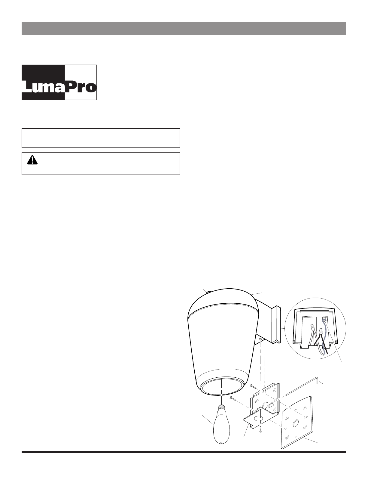
Empaque
(Opcional)
Consola de
Montaje
Fotocontrol
Tornillo para Conexión a Tierra
Artefacto
Bombilla
Clavija
Provisional
ADVERTENCIA: Apague la energía en el fusible
o cortacircuitos.
598-1319-02 S
LPG-5659, LPG-5679
HEA 012
Impreso en la China
02/08
Por favor lea y guarde estas instrucciones. Léalas cuidadosamente antes de intentar armar, instalar, operar o dar
mantenimiento al producto descrito. Protéjase Ud. y los otros observando toda la información de seguridad. ¡Si no lo
hace podría ocasionar lesión al personal y/o daño al equipo! Guarde estas instrucciones para referencia futura.
Manual de Instrucciones y Partes 2LBL7, 2LBL8
Modelo 2LBL7 : Luz de patio con halogenuro de metal de 50 vatios
Modelo 2LBL8 : Luz de patio con vapor de sodio a alta presión de 70 vatios
®
La lámpara en el dispositivo contiene mercurio.Deseche
de acuerdo con las leyes locales, estatales o federales.
This manual suits for next models
1
Table of contents
Languages:
Popular Landscape Lighting manuals by other brands

LIGMAN
LIGMAN MALTA 1 installation manual

Saxby Lighting
Saxby Lighting Islay 68784 Instruction leaflet

LIGMAN
LIGMAN EU-10016-3 installation manual

LIGMAN
LIGMAN KI-60475 installation manual

Cooper Lighting
Cooper Lighting McGraw-Edison ZD Credenza specification

Cooper Lighting
Cooper Lighting Generation CLB25MWW5C373 Specification sheet

Malibu Boats
Malibu Boats CM110P instructions

AMP Lighting
AMP Lighting OrchardPro APL-3018-B-BZ Installation & maintenance guide

Cooper Lighting
Cooper Lighting Invue 42 - 175W Specification sheet

ABBA
ABBA SPB12 installation guide

Techmar
Techmar Garden Lights GILVUS + manual

LIGMAN
LIGMAN RADO 1 installation manual