Lumascape Vestalux V2 LS9016 User manual

INSTALLATION INSTRUCTIONS
FACADE OUTLINER
Vestalux V2 LS9016
ASIA PACIFIC 18 Brandl Street, Eight Mile Plains, QLD 4113, Australia P: +61 7 3854 5000 | F: +61 7 3854 5001 | E: [email protected] | lumascape.com.au
NORTH AMERICA 1940 Diamond Street, San Marcos, CA 92078, USA P: +1 650 595 5862 | F: +1 650 595 5820 | E: [email protected] | lumascape.com
1 /8IN0184-200717
Products and specifications are subject to change without notice.
Product Warranty is void if product is not installed as per installation
instructions and in compliance with all local and provincial codes.
›Follow all safety instructions carefully. Failure to do so will
void warranty.
›Ensure installation complies with local electrical rules and
regulations.
›Input voltage range 30-48 Vdc.
›Only use Lumascape power supply, control equipment and
leader cables.
›Ensure mains input power is surge protected.
›Never make connections while the power is connected.
›Do not make modifications or alter the product.
›Keep lminaire clean and free of debris.
›Only clean with warm water.
›Do not use chemicals or abrasives to clean luminaire as this may
void the product warranty.
›Connectors are to be kept clean and dry at all times.
›Once installed, all connectors are to be mated and a terminating
plug is required on the last fitting of run.
READ ALL SAFETY INSTRUCTIONS FIRST
NO POWER
TOOLS
KEEP AWAY FROM
FLAMMABLE MATERIAL
DO NOT USE SILICONE
ON OUTSIDE SURFACE
KEEP ELECTRONICS FREE
FROM DIRECT AND MOISTURE
DO NOT HOSE OR
PRESSURE CLEAN
DO NOT USE CHEMICALS
OR ABRASIVES
A
A+
A++

INSTALLATION INSTRUCTIONS
FACADE OUTLINER
Vestalux V2 LS9016
ASIA PACIFIC 18 Brandl Street, Eight Mile Plains, QLD 4113, Australia P: +61 7 3854 5000 | F: +61 7 3854 5001 | E: [email protected] | lumascape.com.au
NORTH AMERICA 1940 Diamond Street, San Marcos, CA 92078, USA P: +1 650 595 5862 | F: +1 650 595 5820 | E: [email protected] | lumascape.com
2 / 8 IN0184-200717
Products and specifications are subject to change without notice.
Bracket Mounting Orientations
A
C
B
D
E
F
G
H
Product Overview
Below is a general overview of a typical LS9016 setup. The Leader
Cable (A) connects to the LS6550 DIN Rail PowerSync™ Supply.
For details on setting-up LS6550 refer to the supply specific
installation instructions.
The Leader Cable (A) connects to the first Luminaire Input (B) via an
IP68 quick connector. The LS9016 is designed for loop-in, loop-out.
The output (C) of the previous luminaire will connect to the input (B)
of the next luminaire. At the end of the run the luminaire chain has to
be terminated with a Terminator (H).
Luminaires come with Mounting Brackets: Fixed (E) or Adjustable (D)
and Cable Holders (G). Luminaires come in 1 ft, 2 ft, 3 ft, 4 ft and 5
ft lengths. Mounting Brackets: Fixed (E) or Adjustable (D) and Cable
Holders (G) need to be attached to the luminaires before mounting.
It is recommended installers use SS316 screws per Mounting Bracket
type: 2 x Fixed (E) or 1 x Adjustable (D) to secure the luminaire to
the substrate.
COMPONENT LIST
A Leader Cable
B Luminaire Input
C Luminaire Output
D Adjustable Mounting Bracket
E Fixed Mounting Bracket
F Mounting Board
G Cable Holder
H Terminator

INSTALLATION INSTRUCTIONS
FACADE OUTLINER
Vestalux V2 LS9016
ASIA PACIFIC 18 Brandl Street, Eight Mile Plains, QLD 4113, Australia P: +61 7 3854 5000 | F: +61 7 3854 5001 | E: [email protected] | lumascape.com.au
NORTH AMERICA 1940 Diamond Street, San Marcos, CA 92078, USA P: +1 650 595 5862 | F: +1 650 595 5820 | E: [email protected] | lumascape.com
3 /8IN0184-200717
Products and specifications are subject to change without notice.
Product Overview
End View Mounting Bracket
Side View
Fixed Vertical Mounting
Adjustable Horizontal Mounting
Mounting Orientations
3.2" (81 mm)
3.2" (81 mm)
1.5" (39 mm) 1.5" (39 mm)
2.2" (57 mm)
3.5" (89 mm)
1.8" (45 mm)
12.7" (323 mm)
24.5" (622 mm)
36.2" (920 mm)
48.0" (1,219 mm)
59.7" (1,517 mm)
3.5" (89 mm)

INSTALLATION INSTRUCTIONS
FACADE OUTLINER
Vestalux V2 LS9016
ASIA PACIFIC 18 Brandl Street, Eight Mile Plains, QLD 4113, Australia P: +61 7 3854 5000 | F: +61 7 3854 5001 | E: [email protected] | lumascape.com.au
NORTH AMERICA 1940 Diamond Street, San Marcos, CA 92078, USA P: +1 650 595 5862 | F: +1 650 595 5820 | E: [email protected] | lumascape.com
4 / 8 IN0184-200717
Products and specifications are subject to change without notice.
Attaching Adjustable Bracket
Step 1
Step 2
Screw adjustable bracketry to mounting board on underside of luminaire and screw bracket in place. Repeat until all
four screws are firmly in place. NOTE: The adjustable mounting bracket is reversible.
OR
Torque: 1.5 N.m.
Use allen key to loosen bracket’s tilt mechanism and adjust the tilt of the mounting bracket.
Tighten to lock bracketry in place.
Unlock Adjust Lock

INSTALLATION INSTRUCTIONS
FACADE OUTLINER
Vestalux V2 LS9016
ASIA PACIFIC 18 Brandl Street, Eight Mile Plains, QLD 4113, Australia P: +61 7 3854 5000 | F: +61 7 3854 5001 | E: [email protected] | lumascape.com.au
NORTH AMERICA 1940 Diamond Street, San Marcos, CA 92078, USA P: +1 650 595 5862 | F: +1 650 595 5820 | E: [email protected] | lumascape.com
5 /8IN0184-200717
Products and specifications are subject to change without notice.
Attaching Fixed Bracket
Attaching Cable Holder
Step 1 Screw fixed bracketry to mounting board on underside of luminaire and screw bracket in place. Repeat until all four
screws are firmly in place.
Torque: 1.5 N.m.
Step 1 Clip the cable under the cable holder. Pinch firmly to remove and re-attach cable holders. Repeat these steps for each
cable holder on each luminaire. NOTE: This is not applicable for 1 ft luminaires.

INSTALLATION INSTRUCTIONS
FACADE OUTLINER
Vestalux V2 LS9016
ASIA PACIFIC 18 Brandl Street, Eight Mile Plains, QLD 4113, Australia P: +61 7 3854 5000 | F: +61 7 3854 5001 | E: [email protected] | lumascape.com.au
NORTH AMERICA 1940 Diamond Street, San Marcos, CA 92078, USA P: +1 650 595 5862 | F: +1 650 595 5820 | E: [email protected] | lumascape.com
6 / 8 IN0184-200717
Products and specifications are subject to change without notice.
Mounting the Luminaire
Step 4 Repeat the above steps to mount every luminaire in the chain. When
placing the luminaires in an end-to-end setup, be sure to leave a
minimum gap of 0.4" (10 mm) to allow for thermal expansion.
Minimum thermal expansion
gap between luminaires
0.4"
(10 mm)
Step 1 It is recommended to mount the luminaire with 316 stainless steel screws. To start, put a single screw into one
bracket. Use a spirit level or digital inclinometer to make sure the luminaire is level. Once the luminaire is level secure
with a second screw on the opposing side.
Step 2 Insert the remaining screws required. Each adjustable mounting bracket should be secured with one 316 stainless
steel screw. Each fixed mounting bracket should be secured with two 316 stainless steel screws.

INSTALLATION INSTRUCTIONS
FACADE OUTLINER
Vestalux V2 LS9016
ASIA PACIFIC 18 Brandl Street, Eight Mile Plains, QLD 4113, Australia P: +61 7 3854 5000 | F: +61 7 3854 5001 | E: [email protected] | lumascape.com.au
NORTH AMERICA 1940 Diamond Street, San Marcos, CA 92078, USA P: +1 650 595 5862 | F: +1 650 595 5820 | E: [email protected] | lumascape.com
7 /8IN0184-200717
Products and specifications are subject to change without notice.
Electrical Connection
Step 1 Once the physical components have been installed it is time to complete the electrical installation.
Step 2 Power up the circuit to test the installation.
Luminaire to Luminaire
Connect the output of the previous
luminaire to the input of the next
luminaire in the chain and tighten
the connectors. Do this for all the
luminaires within the chain.
Leader Cable
Connect the leader cable
to the input of the first
luminaire in the chain and
tighten the connectors.
Terminator
Attach the terminator
to the output of the
last luminaire in the
chain and tighten.
LABEL
Wire Colour Designation
Positive Red
Negative Black
Data Orange
Low Voltage

INSTALLATION INSTRUCTIONS
FACADE OUTLINER
Vestalux V2 LS9016
ASIA PACIFIC 18 Brandl Street, Eight Mile Plains, QLD 4113, Australia P: +61 7 3854 5000 | F: +61 7 3854 5001 | E: [email protected] | lumascape.com.au
NORTH AMERICA 1940 Diamond Street, San Marcos, CA 92078, USA P: +1 650 595 5862 | F: +1 650 595 5820 | E: [email protected] | lumascape.com
8 / 8 IN0184-200717
Products and specifications are subject to change without notice.
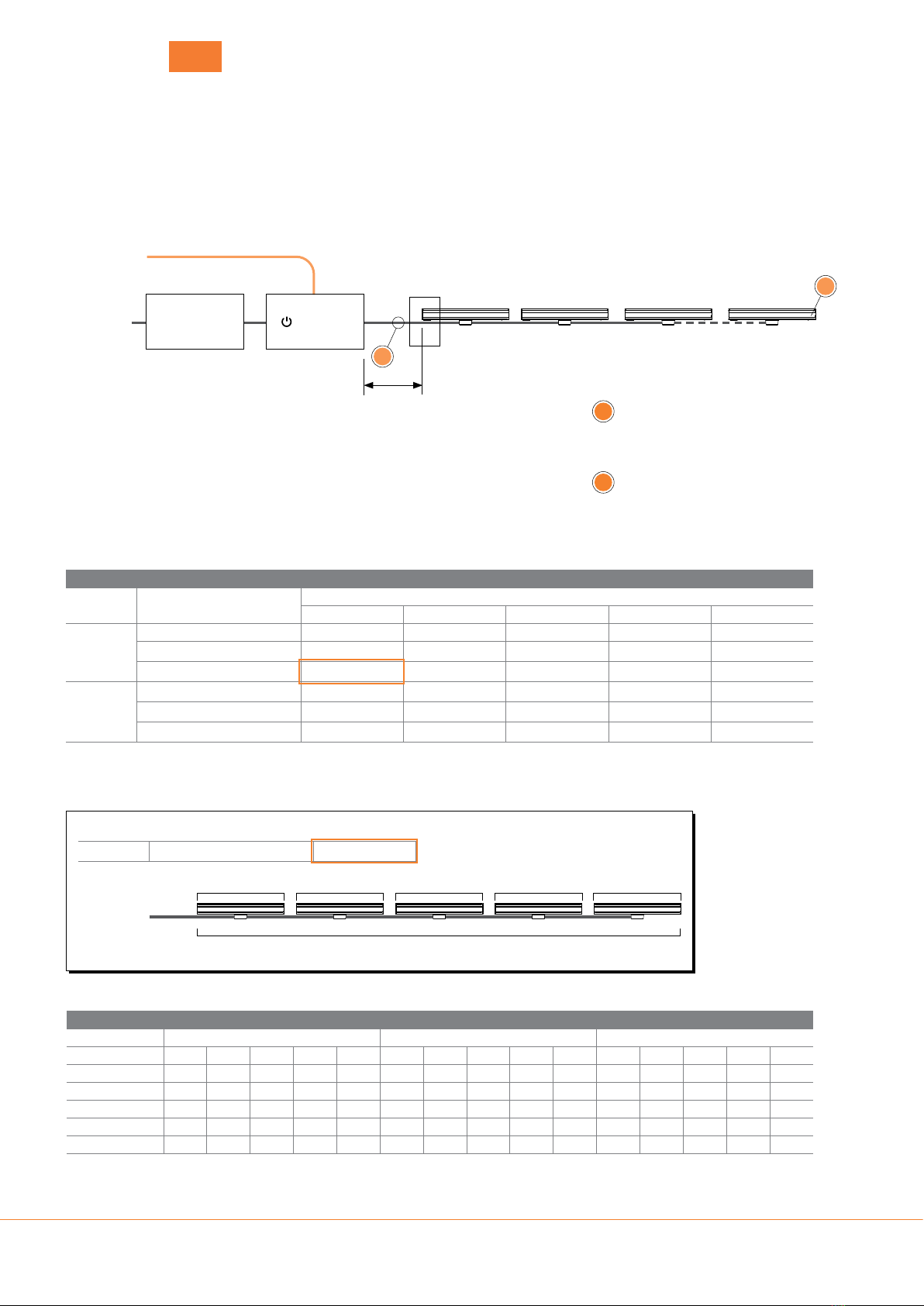
Network Topology – Low Voltage PowerSync™
DMX Channel Allocation
RGBA / RGBW Single Colour Tunable White
Pixel Size 1 ft 2 ft 3 ft 4 ft 5 ft 1 ft 2 ft 3 ft 4 ft 5 ft 1 ft 2 ft 3 ft 4 ft 5 ft
Full Fixture 4 4 4 4 4 1 1 1 1 1 2 2 2 2 2
12.0" / 300 mm 4 8 12 16 20 1 2 3 4 5 2 4 6 8 10
6.0" / 150 mm 8 16 24 32 40 2 4 6 8 10 4 8 12 16 20
3.0" / 75 mm 16 32 48 64 80 4 8 12 16 20 8 16 24 32 40
1.0" / 19 mm 64 128 192 256 320 16 32 48 64 80 32 64 96 128 160
Extra channels required when enabling optional Advanced Control Modes.
• Variable Dimming Smoothness Mode - requires 1 extra channel per luminaire
• Variable Dimming Smoothness + Strobe Mode - requires 3 extra channels per luminaire
Maximum Circuit Loading - Single Run
LED Power Max Leader Cable Length from
LS6550 to first fitting
Feet of Linear luminaire per 48 V Power Supply
120 W 240 W 320 W 480 W 600 W
4 W/ft
50 ft / 15 m 20 44 56 80 96
98 ft / 30 m 20 44 56 76 88
164 ft / 50 m 20 40 52 64 72
6 W/ft
50 ft / 15 m 14 28 36 56 64
98 ft / 30 m 14 28 36 48 56
164 ft / 50 m 14 26 34 44 48
Values in the above table show the maximum circuit loading per 48V circuit.
Values are based on end to end spacing (ETE). Extended fixture cables, inclusion of jumper cables, or longer leader cable will eect loading.
Circuits can be made up of up to 24 fixtures in any length, up to the maximum circuit loading in the table above.
Circuits are limited to maximum 12.8A.
For non-continuous runs, contact Lumascape for details.
To calculate the maximum number of interconnected luminaires per run / circuit, see example below.
Up to 24 luminaires per 48V PowerSync™ circuit / LS6550 Low Voltage PowerSync™ Data Injector
Control Resolution
Circuit Calculation Example
4 W/ft 50 m / 164 ft 20
For assistance, contact Lumascape. Always observe electrical codes.
Leader Cable
20ft
4ft 4ft 4ft4ft 4ft
20 ft of linear fixture = 5 x 4 ft luminaires
PowerSync™ Topology 1 - Split Trunk Cable
TTerminator
Use PowerSync™ terminator, supplied
with leader cable to terminate last
luminaire in chain.
IMaximum Current
Through cables and connectors ≤12.8A
T
Control Signal
120-277 Vac
50/60 Hz
Power Supply
(PSU)
LS6550 LV
PowerSync™
Data Injector
easyglow
tm
humantouchtm opticlear
tm p wersync
tm
gripglass
tm electropolish+
tm
microantileachtm cooldrivetm
pure pticstm
I
Leader Cable
Table of contents
Other Lumascape Landscape Lighting manuals
Popular Landscape Lighting manuals by other brands

Volt
Volt VAL-2006-4-BBZ installation instructions

AMP Lighting
AMP Lighting Sol Box ASDL-2014-P-BK Installation & maintenance guide

STERNO HOME
STERNO HOME U000-9214 instructions

Paradise Datacom
Paradise Datacom GL28106 instructions

Tronix
Tronix 140-012 instructions

LIGMAN
LIGMAN LA-60004 installation manual

Cooper Lighting
Cooper Lighting Woodbridge MPW50SR255 Specifications

Effekta
Effekta Emergency luminaire 300 Mounting instructions

Regent Lighting Solutions
Regent Lighting Solutions Quattro Bollard - Buried installation instructions

Malibu Boats
Malibu Boats LZ308 instructions

Garden Lights
Garden Lights RUBUM+ manual

Malibu Boats
Malibu Boats LZ510 instructions