manuals.online logo
Brands
  1. Home
  2. •
  3. Brands
  4. •
  5. Lumel
  6. •
  7. Inverter
  8. •
  9. Lumel PVSA User manual

Lumel PVSA User manual

Popular Inverter manuals by other brands

Omnik New Energy Omniksol-1.5k-TL user manual

Omnik New Energy

Omnik New Energy Omniksol-1.5k-TL user manual

Agilent Technologies 33250A user guide

Agilent Technologies

Agilent Technologies 33250A user guide

4-noks ZR-SWITCH-RC instruction manual

4-noks

4-noks ZR-SWITCH-RC instruction manual

V&T V5 Series user manual

V&T

V&T V5 Series user manual

Hon Turing HT-T-S1000-12 introduction

Hon Turing

Hon Turing HT-T-S1000-12 introduction

Metabo E 140 SP Plus Original operating instructions

Metabo

Metabo E 140 SP Plus Original operating instructions

BARRON EXITRONIX Tucson Micro Series installation instructions

BARRON

BARRON EXITRONIX Tucson Micro Series installation instructions

Baumer HUBNER TDP 0,2 Series Mounting and operating instructions

Baumer

Baumer HUBNER TDP 0,2 Series Mounting and operating instructions

electroil ITTPD11W-RS-BC Operation and Maintenance Handbook

electroil

electroil ITTPD11W-RS-BC Operation and Maintenance Handbook

Silicon Solar TPS555-1230 instruction manual

Silicon Solar

Silicon Solar TPS555-1230 instruction manual

Mission Critical Xantrex Freedom SW-RVC owner's guide

Mission Critical

Mission Critical Xantrex Freedom SW-RVC owner's guide

HP 3312A Operating and service manual

HP

HP 3312A Operating and service manual

Hoymiles HM-500T user manual

Hoymiles

Hoymiles HM-500T user manual

Nitecore SPM10 user manual

Nitecore

Nitecore SPM10 user manual

AEG Protect PV installation manual

AEG

AEG Protect PV installation manual

On Board TruePower Plus 1200MS owner's manual

On Board

On Board TruePower Plus 1200MS owner's manual

Plugreen PGM-200P-230 Installation and operation manual

Plugreen

Plugreen PGM-200P-230 Installation and operation manual

Fourgroup Easy use and Programming Handbook

Fourgroup

Fourgroup Easy use and Programming Handbook

manuals.online logo
manuals.online logoBrands
  • About & Mission
  • Contact us
  • Privacy Policy
  • Terms and Conditions

Copyright 2025 Manuals.Online. All Rights Reserved.

PHOTOVOLTAIC STRING INVERTER
PVSA
USER’S MANUAL
2
3
Contents
1. How to use this manual......................................................................................................................5
1.1 Validity............................................................................................................................................................5
1.2 Target Group..................................................................................................................................................5
1.3 SW version ....................................................................................................................................................5
1.4 Documentation and declaration of conformity ...............................................................................................5
2. Safety Precautions..............................................................................................................................7
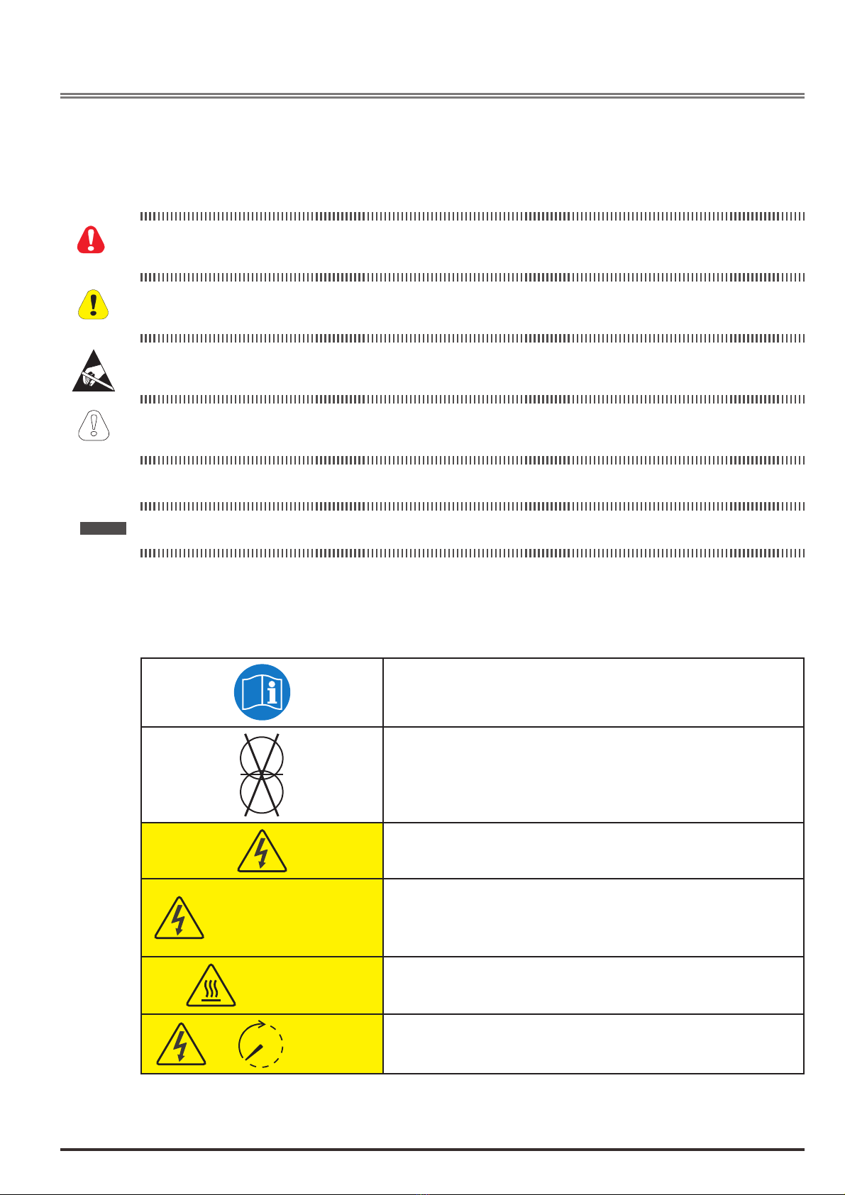
2.1 Symbols used in the manual..........................................................................................................................7
2.2 Symbols used on outside labels ...................................................................................................................7
2.3 General warnings and safety information ......................................................................................................8
2.4 Intended or permitted purpose ......................................................................................................................9
2.5 Improper or prohibited use ............................................................................................................................9
3. Transportation – Handling - Storage...............................................................................................10
3.1 Handling packed equipment ........................................................................................................................10
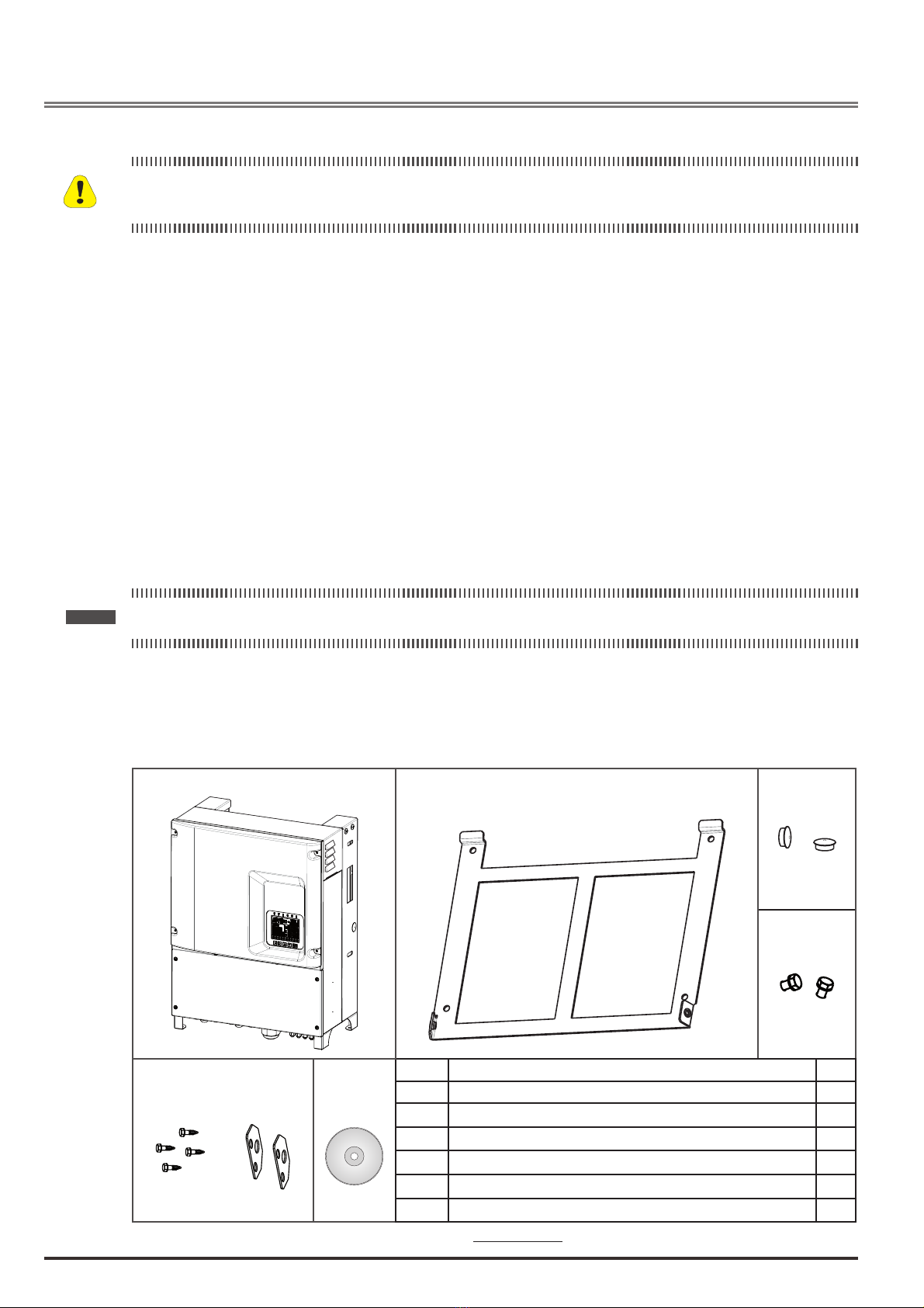
3.2 Packaging and unpacking............................................................................................................................10
3.3 Storage ........................................................................................................................................................ 11
3.4 Handling the equipment after unpacking .....................................................................................................12
3.5 Disposal of the device..................................................................................................................................13
4. Description of the RADIUS PVSA inverter......................................................................................14
4.1 Introduction ..................................................................................................................................................14
4.2 Block diagrams PVSA..................................................................................................................................15
4.3 Installation notes..........................................................................................................................................15
4.4 Device identi!cation.....................................................................................................................................16
4.4.1 Data plate..................................................................................................................................................................16
4.4.2 Model identi!cation (Type) ........................................................................................................................................16
5. Installation .........................................................................................................................................17
5.1 Safety instructions .......................................................................................................................................17
5.2 Selecting the Installation site .......................................................................................................................17
5.3 Mounting ......................................................................................................................................................18
5.3.1 Mounting the device on a wall...................................................................................................................................18
5.3.2 Mounting the inverter on the bracket.........................................................................................................................19
6. Electrical Connection .......................................................................................................................20
6.1 System Diagram with Inverter and Electrical connection.............................................................................20
6.2 Safety...........................................................................................................................................................20
6.3 Removal of the lower panel .........................................................................................................................21
6.4 Connecting to the grid (utility grid) and ground cable (PE) ..........................................................................21
6.4.1 Connecting to the PV panel (DC input) .....................................................................................................................23
6.4.2 Connection PVSA-AE-... models...............................................................................................................................24
6.4.3 Connection PVSA-EE-... models...............................................................................................................................26
6.5 Removing the backup battery protection .....................................................................................................27
6.6 Fixing of the lower panel..............................................................................................................................28
6.7 DC side fuses and string current monitoring................................................................................................29
6.7.1 DC side fuses (integrated inside -F models) .............................................................................................................29
6.7.2 String current monitoring...........................................................................................................................................30
6.8 GROUND KIT ..............................................................................................................................................31
6.9 AC side fuses...............................................................................................................................................32
6.10 Choice of leakage breaker on AC side .......................................................................................................32
6.11 DC circuit breaker ........................................................................................................................................33
6.12 Other connections........................................................................................................................................34
6.12.1 Inputs / Outputs regulation circuit..............................................................................................................................35
6.12.2 Communication .........................................................................................................................................................38
6.12.3 USB functions use.....................................................................................................................................................39
7. Display and Functionality ...............................................................................................................41
7.1 KA Display ...................................................................................................................................................41
7.2 Display KB ...................................................................................................................................................41
7.3 Meaning of LEDs .........................................................................................................................................42
7.3.1 Inverter status: initialization procedure......................................................................................................................42
7.3.2 Inverter status: DC-Grid Connection phase ..............................................................................................................42
7.3.3 Inverter status: Grid Connected ................................................................................................................................42
7.3.4 Inverter status: Generation Ramp .............................................................................................................................42
7.3.5 Inverter status: Generation........................................................................................................................................42
7.3.6 Inverter status: Special Function / Power Limitation .................................................................................................43
7.3.7 Inverter status: Fault ................................................................................................................................................43
7.3.8 Inverter status: Warning ...........................................................................................................................................43
7.4 Meaning and function of keys ......................................................................................................................43
7.5 Commissioning ...........................................................................................................................................44
4
7.6 Display screens: Operating statuses, stand by, alarms and warnings.........................................................46
7.6.1 Operating statuses (advanced level).........................................................................................................................46
7.6.2 Stand-by....................................................................................................................................................................46
7.6.3 Alarms and warnings.................................................................................................................................................46
8. Menu and description of parameters ..............................................................................................48
8.1 Easy menu...................................................................................................................................................48
8.2 Expert menu ................................................................................................................................................49
8.3 Parameters description................................................................................................................................49
8.3.1 Legenda ....................................................................................................................................................................49
9. Communication.................................................................................................................................73
9.1 RS485 serial connection with MODBUS RTU protocol................................................................................73
9.2 Master/Slave alarm monitoring and remote control functions......................................................................75
9.2.1 M/S alarm monitoring function ..................................................................................................................................75
9.2.2 Control function from remote M/S .............................................................................................................................75
10. Troubleshooting................................................................................................................................78
10.1 Error messages classi!cation ......................................................................................................................78
10.2 Alarms and Warnings list .............................................................................................................................78
11. Specifications....................................................................................................................................81
11.1 PVSA-..k-AE models....................................................................................................................................81
11.1.1 Ef!ciency curves .......................................................................................................................................................83
11.2 PVSA-..k-EE models....................................................................................................................................84
11.2.1 Ef!ciency curves .......................................................................................................................................................85
12. Dimensions and weight....................................................................................................................86
13. Maintenance and cleaning ...............................................................................................................87
13.1 Product label................................................................................................................................................87
13.2 Cleaning operations.....................................................................................................................................88
13.3 Routine maintenance procedures................................................................................................................88
13.4 Replacing the backup battery .....................................................................................................................88
14. Warranty conditions .........................................................................................................................90
5
1. How to use this manual
1.1 Validity
This manual describes the assembly, installation, commissioning and maintenance of the following RADIUS
Industrial PVSA Inverters :
PVSA-10k-AE-TL-1... PVSA-10k-AE-TL-2... PVSA-10k-EE-TL-1...
PVSA-12k-AE-TL-1... PVSA-12k-AE-TL-2...
PVSA-15k-AE-TL-2... PVSA-15k-EE-TL-1...
PVSA-18k-AE-TL-2...
PVSA-20k-AE-TL-2... PVSA-20k-AE-TL-3... PVSA-20k-EE-TL-1...
1.2 Target Group
Quali!ed personnel means people who have received training and have proven skills and knowledge of the
construction and operation of this device.
Quali!ed personnel are trained to deal with the dangers and hazards involved in installing electric devices.
1.3 SW version
This manual applies to SW version V1.XX.
The sw uses FreeRTOS™ (www.freertos.org).
1.4 Documentation and declaration of conformity
This technical documentation describes the procedures that must be followed in order to ensure safety during
the transportation, installation, use and maintenance of the electrical equipment to which the manual refers.
Store this manual so that it can be referred to whenever necessary.
Lumel declares that the equipment conforms to current law in the country of installation.
Grid code CEI 0-16– CEI 0-21
VDE- AR – N 4105
RD1669 - RD661
VDE 0126-1-1: 2006-02
VDE 0126-1-1/A1: 2012-02
Photovoltaic (PV) systems.
Characteristics of the utility interface.
IEC 61727: 2004
Electromagnetic Compatibility (EMC) EN 61000-6-2/-3
Procedure for measuring efficiency. IEC 61683
Environmental testing IEC 60068-2-1, 60068-2-2, 60068-2-14, 60068-2-30
Anti islanding IEC 62116: 2008
6
Safety of power converters for use in photovoltaic power systems IEC 62109-1, 62109-2
7
2. Safety Precautions
2.1 Symbols used in the manual
Indicates a procedure, condition, or statement that, if not strictly observed, could result in personal injury or
death.
Indicates a procedure, condition, or statement that, if not strictly observed, could result in damage to or
destruction of equipment.
Indicates that the presence of electrostatic discharge could damage the appliance. When handling the
boards, always wear a grounded bracelet.
Indicates a procedure, condition, or statement that should be strictly followed in order to optimize these ap-
plications.
Note ! Indicates an essential or important procedure, condition, or statement.
2.2 Symbols used on outside labels
Indicates that you must read the manual before doing any work.
Indicates absence of the isolation transformer.
Indicates risk of electrocution due to high voltage.
All work on the inverter must be done ONLY by trained technicians.
Warning
Multiple power supply
Indicates risk of electric shock.
Machine equipped with multiple power supply (DC and AC).
Before doing any work, check that both the DC and the AC power
supply have been disconnected.
Warning
Hot surface
Indicates risk of burning due to very hot surfaces.
Before doing any work, let the unit cool suf!ciently; wear personal
protective equipment (for example, gloves).
10 minutes
Indicates risk of electric shock.
Before doing any work, allow all stored energy to drain for at least
10 minutes.
Warning!
Caution
Attention
8
2.3 General warnings and safety information
Please read these instructions carefully in order to ensure your personal safety and that of others and to pro-
long the service life of this product and of the plant connected to it.
Operators must be instructed or skilled persons. They must have read and fully understood the operating
instructions contained in this manual and those relating to the machine before having access to equipment
controls. Persons who are not skilled or instructed must not be allowed to use the equipment.
The term “specially trained and competent” operator refers to the person responsible for installing and
transporting the electrical equipment.
According to standard CEI EN 60204-1:
A skilled person: is a person with technical knowledge or suf!cient experience to be able to avoid the dangers
which electricity may create.
An instructed person: is a person adequately advised or supervised by skilled persons to be able to avoid the
dangers which electricity may create (e.g. maintenance operators).
Safety Instructions
All maintenance operations carried out on live equipment can involve serious risks. These operations must
be carried out by skilled persons who are fully aware of the risks and provided with all the appropriate per-
sonal protective equipment and suitable tools.
To remove all dangerous voltage from inside the panel, disconnect all the external power connections (AC
side, DC side and auxiliary voltage) and make sure these cannot be reconnected inadvertently (put up a work
in progress sign).
Energy stored in the equipment’s DC link capacitors can be an electric shock hazard. Even after the unit is
disconnected from the grid and photovoltaic panels, there may still be high voltages in the PVSA inverter. Do
not remove the casing (terminal side) until at least 10 minutes after disconnecting all power sources.
Follow all the safety instructions in this manual.
Make sure all power supplies have been disconnected before touching any parts.
Do not modify circuits or software programs or make adjustments without the manufacturer’s prior consent.
Any such modifications could pose a risk for persons or equipment.
Failure to comply with the manufacturerís instructions when using the inverter could undermine safety.
The installer is responsible for choosing the most appropriate residual current-operated circuit breaker ac-
cording to the characteristics of the PV plant.
Danger of burn injuries due to hot enclosure parts!
• Some parts of the equipment may become very hot during operation. DO NOT touch the heat sink while
the inverter is working.
Grounding the PV generator
• Comply with local requirements for grounding the PV modules and the PV generator.
• Lumel recommends connecting the generator frame and other electrically conductive surfaces in a man-
ner which ensures continuous conduction and grounding these in order to achieve maximum protection
of the system and personnel.
Caution
Warning!
Caution
9
2.4 Intended or permitted purpose
This device is a multistring inverter designed to:
convert direct current (DC) from a PV generator into alternating current (AC) suitable for connection to a
3-phase public grid.
Limits of use:
- The inverter can be used only with PV modules that do not require grounding of one of the poles.
- For PV modules that require grounding of one of the poles, use the dedicated version of the product (-P/-N
depending on the grounded pole) and an external transformer (as described in the speci•c addendum).
- Only a PV generator can be connected to the inverter in input (DO NOT connect batteries or other power
sources).
- The inverter can be connected to the grid only in quali•ed countries.
- The inverter can be used only by respecting all of the technical characteristics.
Use the equipment ONLY for its INTENDED OR PERMITTED PURPOSE. If you need any explanations, please
contact Lumel.
2.5 Improper or prohibited use
NEVER:
- Install the equipment in potentially flammable / explosive environments or in environments with adverse or
prohibited conditions (temperature and humidity).
- Use the equipment with defective or disabled safety devices.
- Use the equipment or parts of the equipment by connecting it to other machines or devices (unless specifi-
cally permitted).
- Modify work parameters not accessible to the operator and/or any parts of the equipment to change its
performance or insulations.
10
3. Transportation – Handling - Storage
All transportation, handling and storage operations must only be performed by specially trained and compe-
tent operators.
3.1 Handling packed equipment
The equipment can easily be transported using a lift truck, or fork crane with adequate load capacity,
Dimensions and weights are speci•ed in chapter “12. Dimensions and weight” on page 86.
Correct methods of transportation, storage, installation and assembly, as well as appropriate use and mainte-
nance, are essential for ensuring the proper and safe operation of this equipment.
Protect the equipment against shocks and vibrations during transportation.
Make sure it is also protected against water (rain), humidity and extreme temperatures.
3.2 Packaging and unpacking
The packaging consists of a wooden crate and 2 expanded Polyethylene(EP) protectors. Wooden crate dimen-
sions: 800x600x505 mm.
Note ! These materials must be disposed of in accordance with local regulations.
As soon as the equipment is delivered check that:
- there is no visible damage to packaging,
- the details in the delivery note correspond to the order.
- after opening the package, please check the contents of the box. It should contain the following:
(A) (B) (C)
(D)
(E) (F)
REF. Description Q.ty
A PVSA-.... Inverter 1
B Mounting bracket 1
CPlastic caps 2
DM8 x 25 bolts 2
E2 transport brackets and 4 M8 x 25 hexagonal head screws 2+4
F
CD-ROM (containing manuals in PDF format and configuration software)
1
Figure 1 : Packaging contents
Caution