Techno Sun OFF1307 User manual

11KW
Solar Inverter
Version: 1.0
User Manual

Table of Contents
ABOUT THIS MANUAL ......................................................................................................................................1
Purpose............................................................................................................................................................1
Scope ...............................................................................................................................................................1
SAFETY INSTRUCTIONS...................................................................................................................................1
INTRODUCTION .................................................................................................................................................2
Features...........................................................................................................................................................2
Basic System Architecture ...............................................................................................................................2
Product Overview.............................................................................................................................................3
Unpacking and Inspection ...............................................................................................................................4
Preparation ......................................................................................................................................................4
Mounting the Unit.............................................................................................................................................4
Battery Connection ..........................................................................................................................................5
AC Input/Output Connection............................................................................................................................6
PV Connection .................................................................................................................................................8
Final Assembly.................................................................................................................................................9
Communication Connection...........................................................................................................................10
Dry Contact Signal and RSD Control............................................................................................................. 11
OPERATION......................................................................................................................................................12
Power ON/OFF ..............................................................................................................................................12
Operation and Display Panel .........................................................................................................................12
Pages Information..........................................................................................................................................13
LCD Setting....................................................................................................................................................14
Warning and Fault List ...................................................................................................................................18
CLEARANCE AND MAINTENANCE FOR ANTI-DUST KIT............................................................................19
Overview ........................................................................................................................................................19
Clearance and Maintenance ..........................................................................................................................19
BATTERY EQUALIZATION ..............................................................................................................................20
SPECIFICATIONS .............................................................................................................................................21
Table 1 Line Mode Specifications ...................................................................................................................21
Table 2 Inverter Mode Specifications .............................................................................................................22
Table 3 Charge Mode Specifications...............................................................................................................23
Table 4 General Specifications........................................................................................................................23
TROUBLE SHOOTING .....................................................................................................................................25
Appendix I: Parallel function ..........................................................................................................................27
Appendix II: BMS Communication Installation.............................................................................................37
Appendix III: The Wi-Fi Operation Guide.......................................................................................................40
Appendix IV: The CT Operation Guide ..........................................................................................................50

1
ABOUT THIS MANUAL
Purpose
This manual describes the assembly, installation, operation and troubleshooting of this unit. Please read
this manual carefully before installations and operations. Keep this manual for future reference.
Scope
This manual provides safety and installation guidelines as well as information on tools and wiring.
SAFETY INSTRUCTIONS
WARNING: This chapter contains important safety and operating instructions. Read and keep
this manual for future reference.
1. Before using the unit, read all instructions and cautionary markings on the unit, the batteries and all
appropriate sections of this manual.
2. CAUTION –To reduce risk of injury, charge only deep-cycle lead acid type rechargeable batteries.
Other types of batteries may burst, causing personal injury and damage.
3. Do not disassemble the unit. Take it to a qualified service center when service or repair is required.
Incorrect re-assembly may result in a risk of electric shock or fire.
4. To reduce risk of electric shock, disconnect all wirings before attempting any maintenance or cleaning.
Turning off the unit will not reduce this risk.
5. CAUTION –Only qualified personnel can install this device with battery.
6. NEVER charge a frozen battery.
7. For optimum operation of this inverter/charger, please follow required spec to select appropriate cable
size. It’s very important to correctly operate this inverter/charger.
8. Be very cautious when working with metal tools on or around batteries. A potential risk exists to drop
a tool to spark or short circuit batteries or other electrical parts and could cause an explosion.
9. Please strictly follow installation procedure when you want to disconnect AC or DC terminals. Please
refer to INSTALLATION section of this manual for the details.
10. Fuses are provided as over-current protection for the battery supply.
11. GROUNDING INSTRUCTIONS -This inverter/charger should be connected to a permanent grounded
wiring system. Be sure to comply with local requirements and regulation to install this inverter.
12. NEVER cause AC output and DC input short circuited. Do NOT connect to the mains when DC input
short circuits.
13. Warning!! Only qualified service persons are able to service this device. If errors still persist after
following troubleshooting table, please send this inverter/charger back to local dealer or service
center for maintenance.
14. WARNING: Because this inverter is non-isolated, only three types of PV modules are acceptable:
single crystalline, poly crystalline with class A-rated and CIGS modules. To avoid any malfunction, do
not connect any PV modules with possible current leakage to the inverter. For example, grounded PV
modules will cause current leakage to the inverter. When using CIGS modules, please be sure NO
grounding.
15. CAUTION: It’s required to use PV junction box with surge protection. Otherwise, it will cause
damage on inverter when lightning occurs on PV modules.
2
INTRODUCTION
This is a multi-function inverter, combining functions of inverter, solar charger and battery charger to offer
uninterruptible power support in a single package. The comprehensive LCD display offers user-configurable
and easy-accessible button operations such as battery charging current, AC or solar charging priority, and
acceptable input voltage based on different applications.
Features
Pure sine wave inverter
Built-in LED bars to indicate the energy source and power flow
Touchable button with seven-page colorful LCD
Built-in Wi-Fi for mobile monitoring and OTA firmware upgrade (APP is required)
Supports USB On-the-Go function
Built-in current transformer sensor to meet self-consumption application
Dual outputs for smart load management
Two independent AC power sources connected and switched automatically
Configurable output usage timer and prioritization
Configurable charger source priority
Configurable battery charging current
Reserved communication ports for BMS (RS485, CAN-BUS)
Reserved external BTS (Battery Temperature Sensor) detection
Reserved optional GFCI, Rapid shutdown, AFCI detections
Built-in anti-dusk kit
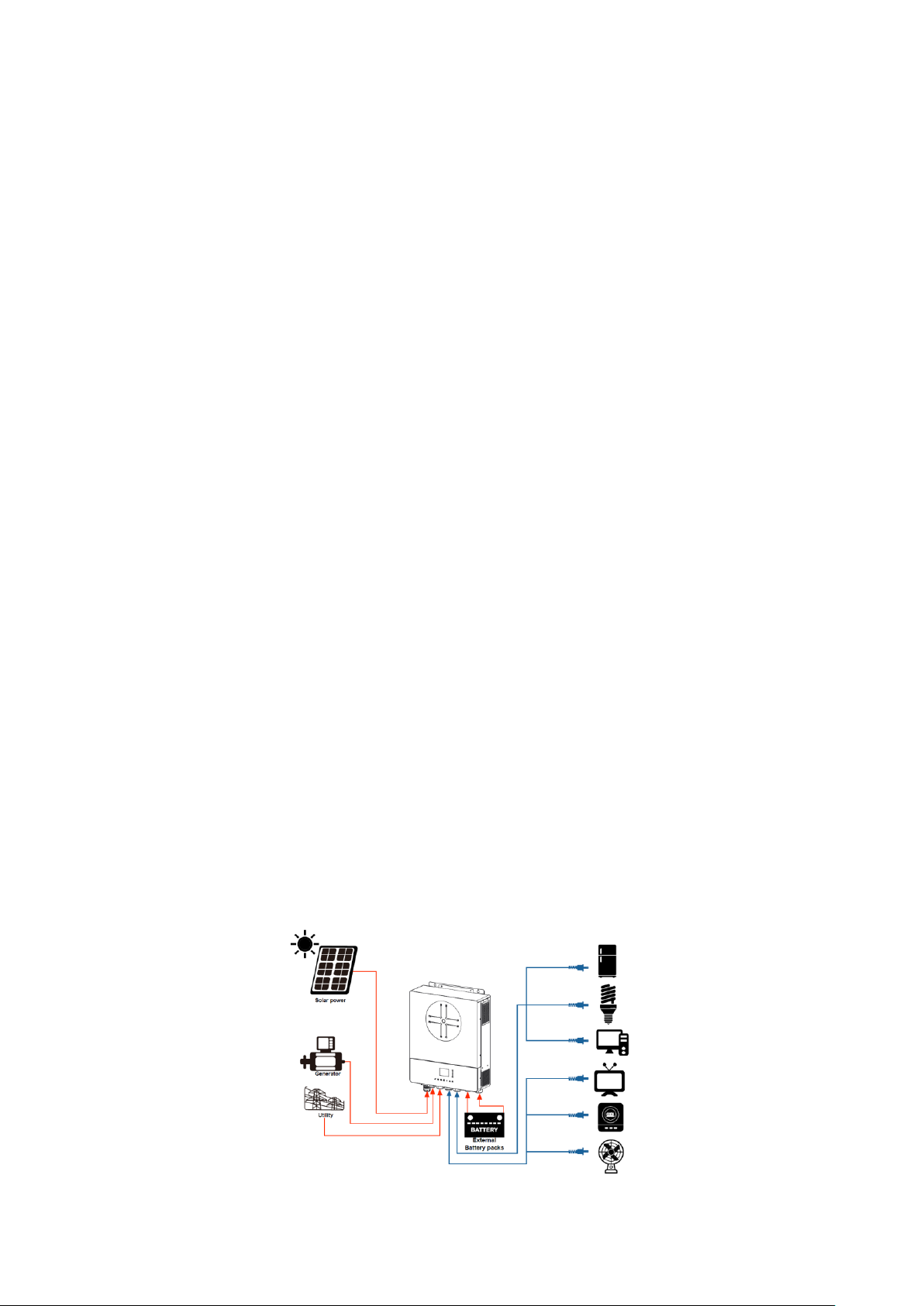
Basic System Architecture
The following illustration shows basic application for this unit. It also required the following devices to have a
complete running system:
Generator or Utility mains.
PV modules
Consult with your system integrator for other possible system architectures depending on your requirements.
This inverter can power various appliances in home or office environment, including motor-type appliances
such as tube light, fan, refrigerator and air conditioners.
Figure 1 Basic hybrid PV System Overview
3
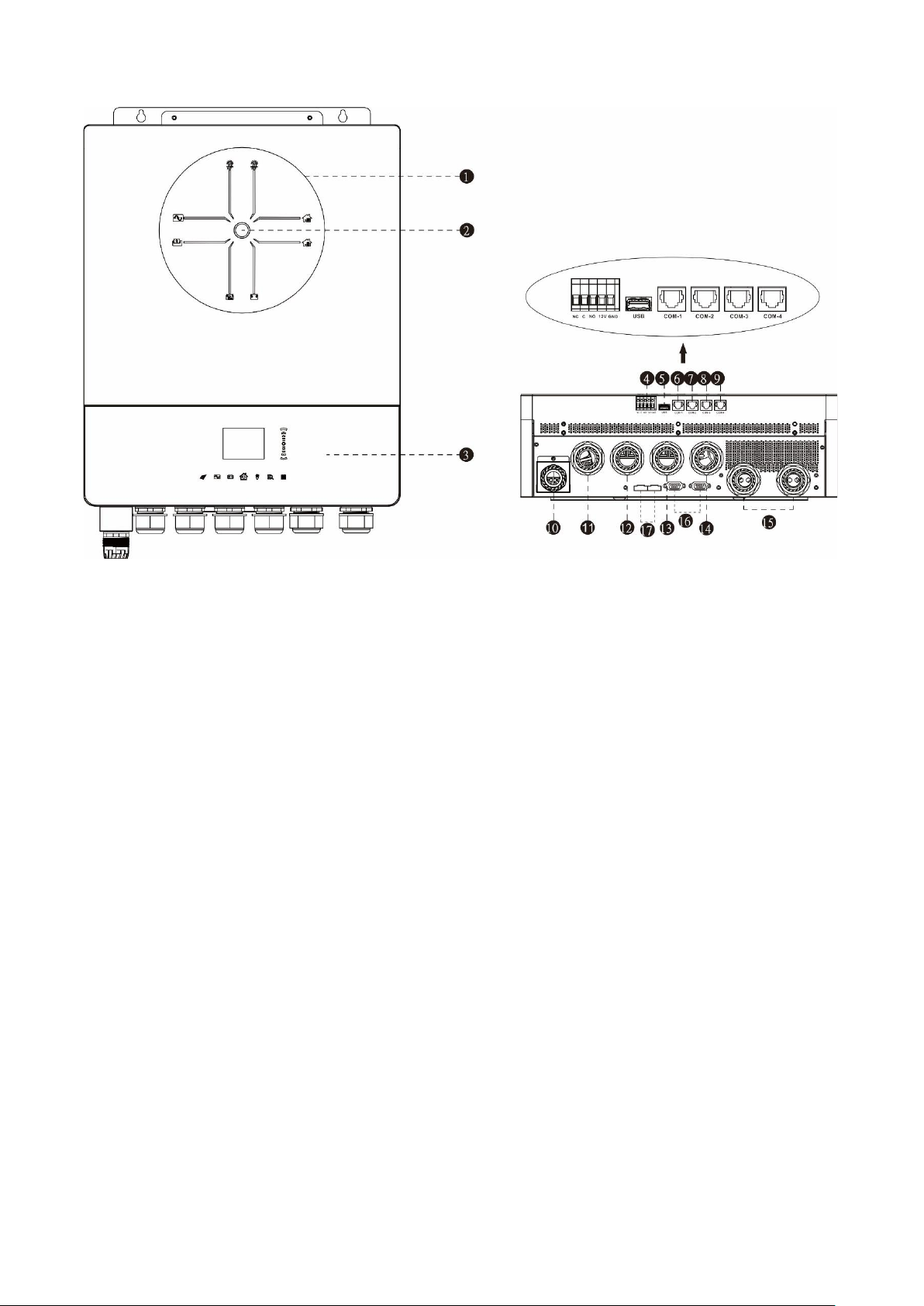
Product Overview
NOTE: For parallel installation and operation, please check
Appendix I.
1. LED indicator bars
2. Power on switch
3. Touchpad function keys and LCD
4. Dry contact port and reserved rapid shutdown control port
5. Type A USB disk port
6. COM1: External BTS port
7. COM2: BMS port
8. COM3: RS232 port
9. COM4: Reserved GFCI, AFCI detection port
10. PV input 1 & 2
11. Generator input
12. Grid input
13. AC output 1
14. AC output 2
15. Battery input
16. Parallel communication port
17. Parallel current sharing port

4
INSTALLATION
Unpacking and Inspection
Before installation, please inspect the unit. Be sure that nothing inside the package is damaged. You should
have received the following items inside of package:
Inverter unit Manual software CD RS-232 cable Parallel communication cable Current sharing cable
+
DC Fuse Cable gland 6+1 pcs PV BOX Screwdriver CT
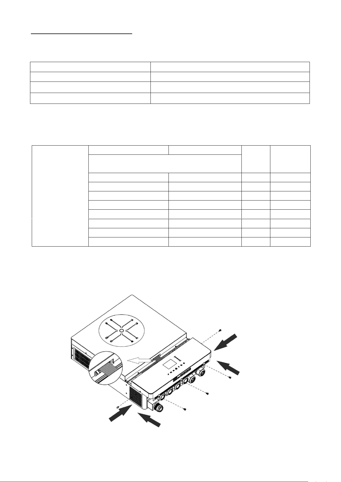
Preparation
Before connecting all wirings, please take off wiring cover by removing five screws. When removing the
bottom cover, be carefully to remove two cables as shown below.
Mounting the Unit
Consider the following points before selecting where to install:
Do not mount the inverter on flammable construction materials.
Mount on a solid surface
Install this inverter at eye level in order to allow the LCD display to be
read at all times.
The ambient temperature should be between 0°C and 55°C to ensure
optimal operation.
The recommended installation position is to be adhered to the wall
vertically.
Be sure to keep other objects and surfaces as shown in the right
diagram to guarantee sufficient heat dissipation and to have enough
space for removing wires.
SUITABLE FOR MOUNTING ON CONCRETE OR OTHER NON-COMBUSTIBLE SURFACE ONLY.

5
Install the unit by screwing four screws. It’s recommended to use M4 or M5 screws.
Battery Connection
CAUTION: For safety operation and regulation compliance, it’s requested to install a separate DC over-current
protector or disconnect device between battery and inverter. It may not be requested to have a disconnect
device in some applications, however, it’s still requested to have over-current protection installed. Please refer
to typical amperage in below table as required fuse or breaker size.
WARNING! All wiring must be performed by a qualified personnel.
WARNING! It’s very important for system safety and efficient operation to use
appropriate cable for battery connection. To reduce risk of injury, please use the
proper recommended cable and terminal size as below.
Recommended battery cable and terminal size:
Typical
Amperage
Battery
capacity
Wire Size
Cable
mm2
Ring Terminal
Torque
value
Dimensions
D (mm)
L (mm)
228A
250AH
1*4/0AWG
85
8.4
54
5 Nm
Please follow below steps to implement battery connection:
1. Assemble battery ring terminal based on recommended battery cable and terminal size.
2. Fix two cable glands into positive and negative terminals.
3. Insert the ring terminal of battery cable flatly into battery connector of inverter and make sure the nuts are
tightened with torque of 5 Nm. Make sure polarity at both the battery and the inverter/charge is correctly
connected and ring terminals are tightly screwed to the battery terminals.
WARNING: Shock Hazard
Installation must be performed with care due to high battery voltage in series.
CAUTION!! Do not place anything between the flat part of the inverter terminal and the ring
terminal. Otherwise, overheating may occur.
CAUTION!! Do not apply anti-oxidant substance on the terminals before terminals are connected
tightly.
CAUTION!! Before making the final DC connection or closing DC breaker/disconnector, be sure
positive (+) must be connected to positive (+) and negative (-) must be connected to negative
(-).
Ring terminal:

6
AC Input/Output Connection
CAUTION!! Before connecting to AC input power source, please install a separate AC breaker between
inverter and AC input power source. This will ensure the inverter can be securely disconnected during
maintenance and fully protected from over current of AC input.
CAUTION!! There are two terminal blocks with “IN” and “OUT” markings. Please do NOT mis-connect input
and output connectors.
WARNING! All wiring must be performed by a qualified personnel.
WARNING! It's very important for system safety and efficient operation to use appropriate cable for AC
input connection. To reduce risk of injury, please use the proper recommended cable size as below.
Suggested cable requirement for AC wires
Gauge
Torque Value
8 AWG
1.4~ 1.6Nm
Please follow below steps to implement AC input/output connection:
1. Before making AC input/output connection, be sure to open DC protector or disconnector first.
2. Remove insulation sleeve 10mm for eight conductors. And shorten phase L and neutral conductor N 3mm
3. Install three cable glands on input and output sides.
4. Insert AC input wires according to polarities indicated on terminal block and tighten the terminal screws.
Be sure to connect PE protective conductor ( ) first.
→Ground (yellow-green)
L1→LINE (brown or black)
N1→Neutral (blue)
L2→Generator (brown or black)
N2→Neutral (blue)
WARNING:
Be sure that AC power source is disconnected before attempting to hardwire it to the unit.
5. Then, insert AC output wires according to polarities indicated on terminal block and tighten terminal
screws. Be sure to connect PE protective conductor ( ) first.
→Ground (yellow-green)
L1→LINE (brown or black)
N1→Neutral (blue)
L2→LINE (brown or black)
N2→Neutral (blue)

7
6. Make sure the wires are securely connected.
CAUTION: Important
Be sure to connect AC wires with correct polarity. If L and N wires are connected reversely, it may cause
utility short-circuited when these inverters are worked in parallel operation.
CAUTION: Appliances such as air conditioner requires at least 2~3 minutes to restart because it’s required
to have enough time to balance refrigerant gas inside of circuits. If a power shortage occurs and recovers
in a short time, it will cause damage to your connected appliances. To prevent this kind of damage, please
check manufacturer of air conditioner if it’s equipped with time-delay function before installation. Otherwise,
this inverter/charger will be trigger overload fault and cut off output to protect your appliance but sometimes
it still causes internal damage to the air conditioner.

8
PV Connection
CAUTION: Before connecting to PV modules, please install separately DC circuit breakers between inverter
and PV modules.
NOTE1: Please use 600VDC/30A circuit breaker on each PV input.
NOTE2: The overvoltage category of the PV input is II.
Please follow the steps below to implement PV module connection:
Step 1: Remove the cover plate from the PV input port
Step 2: Install GLAND BUSHING on the PV BOX first and assemble it on the system
Step 3: Confirm the positive and negative marks on the terminal to avoid wrong installation
Prepare the cable and follow the connector assembly process:
I
Step 4: Check correct polarity of connection cable from PV modules and PV input connectors. Then, connect
positive pole (+) of connection cable to positive pole (+) of PV input connector. Connect negative pole (-) of
connection cable to negative pole (-) of PV input connector.
WARNING! For safety and efficiency, it's very important to use appropriate cables for PV module connection.
To reduce risk of injury, please use the proper cable size as recommended below.
Conductor cross-section (mm2)
AWG no.
4~6
10~12
CAUTION: Never directly touch the terminals of inverter. It might cause lethal electric shock.
CAUTION: Keep the cover plate installed if system do not configure with PV panels.
CAUTION: Exceeding the maximum input voltage can destroy the unit!! Check the system before wire connection.
WARNING: Because this inverter is non-isolated, only three types of PV modules are acceptable: single
crystalline and poly crystalline with class A-rated and CIGS modules.
To avoid any malfunction, do not connect any PV modules with possible current leakage to the inverter. For
example, grounded PV modules will cause current leakage to the inverter. When using CIGS modules, please
be sure NO grounding.
CAUTION: It’s required to use PV junction box with surge protection. Otherwise, it will cause damage on
inverter when lightning occurs on PV modules.
Strip one cable 8 mm on both end sides and be careful NOT to nick conductors.
9
Recommended Panel Configuration
When selecting proper PV modules, please be sure to consider the following parameters:
1. Open circuit Voltage (Voc) of PV modules not to exceed maximum PV array open circuit voltage of the
inverter.
2. Open circuit Voltage (Voc) of PV modules should be higher than the start-up voltage.
Max. PV Array Power
11000W
Max. PV Array Open Circuit Voltage
500Vdc
PV Array MPPT Voltage Range
90Vdc~450Vdc
Start-up Voltage (Voc)
80Vdc
Recommended solar panel configuration:
Take the 555Wp PV module as an example. After considering above two parameters, the recommended module
configurations are listed in the table below.
Solar Panel Spec.
(reference)
- 555Wp
- Imp: 17.32A
- Voc: 38.46Vdc
- Isc: 18.33A
- Cells: 110
SOLAR INPUT 1
SOLAR INPUT 2
Q'ty of
panels
Total Input
Power
Min in series: 3pcs, per input
Max. in series: 10pcs, per input
3pcs in series
x
3pcs
1665W
x
3pcs in series
3pcs
1665W
7pcs in series
x
7pcs
3885W
x
7pcs in series
7pcs
3885W
10pcs in series
x
10pcs
5550W
x
10pcs in series
10pcs
5550W
7pcs in series
7pcs in series
14pcs
7770W
10pcs in series
10pcs in series
20pcs
11100W
Final Assembly
After connecting all wirings, re-connect one cables and then put bottom cover back by fixing five screws as
shown below.

10
Communication Connection
Wi-Fi Connection
This unit is equipped with a Wi-Fi transmitter. Wi-Fi transmitter can enable wireless communication between
solar inverters and monitoring platform. Users can access and control the monitored inverter with downloaded
APP. You may find “i.Solar” app from the Apple® Store or Google® Play Store. All data loggers and parameters
are saved in iCloud. For quick installation and operation, please check Appendix III.
Serial Connection (COM1)
This port is reserved to connect an external battery temperature sensor to compensate the charging parameter
to optimize the battery lifecycle. For detailed information, please check with your installer to get the specification
of the optional battery temperature sensor.
BMS Communication Connection (COM2)
It is recommended to purchase a special communication cable if you are connecting to Lithium-Ion battery
modules. Please refer to Appendix II - BMS Communication Installation for details.
Serial Connection (COM3)
Please use the supplied serial cable to connect between the inverter and your PC. Install the monitoring software
from the bundled CD and follow the on-screen instructions to complete your installation. For detailed software
operation, refer to the software user manual on the bundled CD.
Serial Connection (COM4)
This port is reserved to allow the external GFCI or AFCI devices to be integrated to enhance the protection of
solar inverter system. For detailed information, please check with your installer to get the specification of
required GFCI and AFCI devices.

11
Dry Contact Signal and RSD Control
There is one dry contact (3A/250VAC) signal available on the terminal block. It could be used to deliver signal
to external device when battery voltage reaches warning level.
Unit Status
Condition
NC & C
NO & C
Power Off
Unit is off and no output is powered.
Close
Open
Power On
Output is
powered
from Battery
power or
Solar energy.
Output
source
priority set as
USB (utility
first) or SUB
(solar first)
Battery voltage < Low DC
warning voltage
Open
Close
Battery voltage > Setting
value in restart charge or
battery charging reaches
floating stage
Close
Open
Output
source
priority is set
as SBU (SBU
priority)
Battery voltage < Setting
value stop discharge
Open
Close
Battery voltage > Setting
value in restart charge or
battery charging reaches
floating stage
Close
Open
There is another output control port available on the terminal block. It is reserved to allow an external RSD
(Rapid Shutdown Device) to be integrated into this solar inverter system to cut off energy from PV arrays in
case of any emergency conditions. For detailed RSD specification, please check with your installer.
External RSD control

12
OPERATION
Power ON/OFF
Once the unit is properly installed and the batteries are connected well, simply press power switch to turn on
the unit.
Operation and Display Panel
The operation and display panel, shown in below chart, is located on the top of the unit. It includes seven-
page colorful LCD display, scrollbar and graphic touch pads, indicating the operating status and input/output
power information.

13
Pages Information
When the unit is turned on, the LCD display will show home page after few seconds.
Home page: (tap icon 0.5s)
indicates the summarized
power flow and energy
information.
Battery page:
Indicates the battery
information.
Lithium battery
AC input page:
Indicates the dual AC input
information.
PV page:
Indicates the PV information.
AC output page:
Indicates the AC output
information.
Internal data page:
Indicates fan speed and
temperature information.

14
Logs page:
Indicates all event, warning,
and fault messages.
LCD Setting
Press icon for 3s to enter the setting menu.
There are three sub-menus: Information, Basic and Advanced.
Click icon again to exit setting and return to Home page.
Information
Basic
Change the main page
Setup home page
Turn on/off Wi-Fi module
Turn on/off buzzer
Setup date
Setup time
Setup log record duration
Enable screen off timer
Change RGB LED color
Advanced
Configure the nominal voltage and frequency
Default: 230Vac, 50Hz

15
Configure the output and charger source priority
Regular: Priority arranged every day
Schedule: Priority arranged during setting hours
If setting 00hr –00hr, the setting will not be
activated.
Default: Regular
Battery Type
If “User-Defined” is selected, battery charge
voltage and minimum voltage can be set up.
If any lithium battery type is selected, maximum
charging current, CV and floating voltage will be
automatically set up. No need for further setting.
Default: AGM
Configure the stop and restart discharging
voltage/SOC and minimum voltage/SOC
If any types of lithium battery is selected in battery
type, setting value will change to SOC
automatically.
Default: 46V (Stop discharging Volt), 54V (Start re-
discharging Volt), 44V (Minimum Vol Level).
Default: 10% (Stop discharging Volt), 80% (Start
re-discharging Volt), 10% (Minimum Vol Level)
Configure the CV and floating voltage
Default: 56.4V (Charging CV Volt), 54V (Charging
Floating Volt)
Configure the maximum charging current and
limitation while charging from Utility and Generator
Default: 60A (Max charging current), 30A
(Generator charging current), 30A (AC charging
current)
Configure the max. discharging current
Default: Disabled (no limitation)
Configure the compatibility of AC input source
Default: Generator

16
Configure fault or overload behaviors
Default: Disabled, Disabled
Configure the compatibility of AC output mode
Default: Single
Configure battery equalization function, voltage,
time, timeout, interval, activated immediately
Default: Disable (battery EQ function), 58.4V
(Battery EQ Volt), 60 min (Battery EQ time), 120
min, (Battery EQ timeout), 30 days (EQ interval),
Disable (EQ immediately)
Configure cut-off voltage point or SOC and restart
voltage or SOC on the second output (L2).
If any types of lithium battery is selected in
battery type, the setting value will change to SOC
automatically.
Default: 42V (discharge volt on the L2 output), 46V
(Re-discharging volt on the L2 output)
Default: 0% (discharge SOC on the L2 output),
20% (Re-discharging SOC on the L2 output)
Configure discharge time to turn off second
output (L2). And waiting time to turn on the
second output (L2) when the inverter is back to
Line Mode or battery is in charging status
Default: Disable (Discharging Time on the L2
output), 0min (Re-discharging Time on the L2
output)
Configure time interval to turn on the second
output (L2)
Default: 00hr~23hr
Configure external CT function
Default: Disable

17
Specific critical operations activate
(It’s necessary to enter Password 4743 to access)
-Feed power to Grid function
-Reset to factory setting
-Erase all logs
-Export all logs
-Firmware upgrade
Invalid password, try again

18
Warning and Fault List
Code Type
Code #
Event
Code Type
Code #
Event
Fault
F01
Fan fault
Fault
F16
Inv start fault
Fault
F02
High PV-volt
Fault
F17
High dc offset
Fault
F03
High bat-volt
Fault
F18
Over-load
Fault
F04
Low bat-volt
Fault
F19
Amp sense fault
Fault
F05
Output S.C.
Fault
F20
Backfeed fault
Fault
F06
High op-volt
Fault
F21
Firmware fault
Fault
F07
Low op-volt
Fault
F22
Par-CAN fault
Fault
F08
High bus-volt
Fault
F23
Par-host fault
Fault
F09
Low bus-volt
Fault
F24
Par-sync fault
Fault
F10
High PV-amp
Fault
F25
Par-bat fault
Fault
F11
High inv-amp
Fault
F26
Par-grid fault
Fault
F12
High bus-amp
Fault
F27
Par-opa fault
Fault
F13
High disc-amp
Fault
F28
Par-set fault
Fault
F14
Over temp.
Fault
F29
OP Circuit Fault
Fault
F15
Bus start fault
Warning
W01
Grid not exist
Warning
W11
Comm. Lost
Warning
W02
PV not exist
Warning
W12
Par limited
Warning
W03
Pack not exist
Warning
W13
Ip CB trip
Warning
W04
Weak SoC
Warning
W14
EQ warning
Warning
W05
Weak PV-volt
Warning
W15
MCU comm. lost
Warning
W06
Power de-rate
Warning
W16
Disable CHG&
DISCHG
Warning
W07
Heavy load
Warning
W17
Disable CHG
Warning
W08
Temp issue
Warning
W18
Disable DISCHG
Warning
W09
Fan issue
Warning
W19
Force CHG
Warning
W10
BMS lost
Table of contents
Popular Inverter manuals by other brands


Outback Power Systems
Outback Power Systems GFX1424 installation manual

Samlexpower
Samlexpower PST-12S-12A owner's manual

Parweld
Parweld XTM 255i Operator's manual

SPEECON
SPEECON 7300PA series instruction manual

Enerdrive
Enerdrive Gen2 TRUE SINE WAVE user manual

Rohde & Schwarz
Rohde & Schwarz Hameg HM8150 user manual