Veichi AC200 Series User manual

MANUAL
AC200 Series
Frequency Inverter

AC200 Frequency Inverter Maunal
I
CONTENT
Chapter 1 Overview
····························································································· 1
1.1 Safety requirement and cautions ································································································ 1
1.2 Before Use ································································································································· 2
1.3 Technical criterion ····················································································································· 2
Chapter 2 Installation
··························································································· 5
Chapter 3 Keyboard layout and functions specification
···················································· 11
Chapter 4 Function Parameter Table
········································································· 13
4.1 Basic parameters ····················································································································· 13
4.2 Terminal Input and Output Function Selection ·········································································· 42
4.3 Monitor Code ··························································································································· 43
4.4 Fault Code ······························································································································· 44
Chapter 5 Periodic Overhaul and Maintenance
······························································ 45
5.1 Overhaul ·································································································································· 45
5.2 Maintenance ···························································································································· 46
Appendix : Modbus Communication Protocol
······························································· 47

AC200 Frequency Inverter Maunal
1
Chapter 1 Overview
1.1 Safety requirement and cautions
Please do totally understand this part before using the inverter.
Warning signs and meanings
This manual has used following signs which means there is an important part of security. While observing against the
rules, there is a danger of injury even death or machine system damage.
Danger: Wrong operation may cause death or large accident.
Caution: Wrong operation may cause minor wound.
Operation requirement
Only Professional trained person are allowed to operate the equipment. “Professional trained person”means the
workers must experience professional skill train, and must be familiar with installation, wiring, running and maintain and
can rightly deal with emergency cases in use.
Safety guidance
Warning signs come for your security. They are measures to prevent the operator and machine system from damage.
Please carefully read this manual before using and strictly observe the regulations and warning signs while operating.
●
Correct transport, store, installation and careful operation an maintenance are important for inverter safe operation.
In
transport and store process, make sure the inverter is free from impact and vibration. It must be stored where is dry
without corrosive air and conductive dust, and the temperature must be lower than 60℃.
●
This product carries dangerous voltage and controls driver machine with potential danger. If you don’t abide by the
regulations or requirements in this manual, there is danger of body injury even death and machine system damage.
●
Do not wire while the power is connected. Otherwise, there is danger of death for electric shock. Before wiring,
inspection and maintenance, please cut off power supply of all related equipments and ensure main DC voltage in
safe range. And please operate it after 5 mins.
●
Power wire, motor wire and control wire should be all connected firmly. Earth must be reliable and earth resistance
must be lower than 10Ω.
●
Human body electrostatic will damage inner sensitive components seriously. Before operation, please follow ESD
measures. Otherwise, there is danger of inverter damage.
●
Inverter output voltage is pulse wave. If components such as capacitor which improves power factor and
pressure-sensitive resistance for anti-thunder and so on are installed at the output side, please dismantle them or
change to input side.
●
No switch components such as breaker and contactor at the output side. (If there must be one, please make sure the
output current is 0 while the switch acting).
●
No matter where the fault is, there is danger of serious accident. So there must be additional external prevent
measures or other safety devices.
●
Only used in application fields as maker stated. No use in equipments related to special fields such as emergency,
succor, ship, medical treatment, aviation, nuclear and etc.
●
Only Veichi Electric co., ltd service department or its authorized service center can maintain the products. It may
cause product fault while using accessories not authorized or permitted.Any defective components must be changed
in time in maintenance.

AC200 Frequency Inverter Maunal
2
1.2 Before Use
On receiving your order, please check the package and confirm intact before opening, and check if there’s any damage,
scratch or dirt (damages caused during transportation are not within the company's warranty). If there’s any damage
caused during transportation, please contact us or the transport company immediately.After confirming the receipt of the
goods intact, please re-confirm if the product and your order are consistent.
Voltage 220V 380V 660V 1140V Voltage 220V 380V 660V 1140V
Power Rated Output Current (A) Power Rated Output Current (A)
0.4 2.5 110 380 210 121 75
0.75 4 2.5 132 420 250 150 86
1.5 7 3.7 160 550 310 175 105
2.2 10 5.0 185 600 340 198 115
4 16 10 200 660 380 218 132
5.5 20 13 220 720 415 235 144
7.5 30 17 10 250 470 270 162
11 42 25 15 280 510 330 175
15 55 32 18 315 600 345 208
18.5 70 38 22 355 670 380 220
22 80 45 28 400 750 430 260
30 110 60 35 450 800 466 270
37 130 75 45 25 500 860 540 325
45 160 90 52 31 560 990 600 365
55 200 110 63 38 630 1100 680 400
75 260 150 86 52 710 1260 750 480
90 320 180 98 58
1.3 Technical criterion
Items Criterion
Power
input
Voltage,frequency
Single phase 220V 50Hz/60Hz
Three phase 380V 50Hz/60Hz Three phase 220V 50Hz/60Hz
Three phase 660V 50Hz/60Hz Three phase 1140V 50Hz/60Hz
Allowable fluctuations voltage unbalance rate:<3%;Frequency:±5%; aberration rate: as
IEC61800-2 required
Inrush current Lower than rated current
Power factor ≥0.94(with DC reactor)
Efficiency ≥96%
Output Output voltage Output under rated condition:3 phase, 0V~input voltage, inaccuracy<5%
Input
Inverter Model
Output
Power Level
Series No.

AC200 Frequency Inverter Maunal
3
Output frequency range G type:0Hz-600Hz
Output frequency accuracy
Max frequency ±0.5%
Overload capacity G type:150% rated current/1 min, 180% rated current/10s, 200% rated
current/0.5s
Main
Control
performance
Motor control mode V/F without PG ,VC without PG, V/F with PG,VC with PG
Modulate mode Optimized SVPWM mode
Carrier frequency 0.7kHz~16.0kHz
Speed range VC without PG: rated load 1:100
VC with PG: rated load 1:1000
Steady speed accuracy VC without PG: ≤2% rated synchronized speed
VC with PG: ≤0.05% rated synchronized speed
Starting torque VC without PG: when 0.5Hz, 150% rated torque
VC with PG: when 0Hz, 200% rated torque
Torque response VC without PG: ≤20ms
VC with PG: ≤10ms
Frequency accuracy Digit setting:max frequency×±0.01%
Analog setting:max frequency×±0.2%
Frequency resolution Digit setting:0.01Hz
Analog setting:max frequency×0.05%
Basic
functions
DC braking capacity
Starting frequency:0.00Hz~50.00Hz
Braking time:0.0s~60.0s
Braking current:0.0%~150.0% rated current
Torque upgrade capacity Auto torque upgrade 0.0%~100.0%
Manual torque upgrade 0.0%~30.0%
V/F curve
4 modes: one linearity torque characteristic curve ,one user setting V/F
curve mode, one drop torque characteristic curve (1.1- 2.0 powers) and
square V/F curve mode.
Acceleration/Deceleration
curve
2 modes: linear Acceleration/Deceleration and S curve
Acceleration/Deceleration.4 sets of Acceleration/Deceleration time ,unit
0.01s selectable, longest time: 650.00s.
Rated output voltage Rely on power supply voltage compensate function, while motor rated
voltage is 100%, set it at the range of 50-100%(output can not over input
Voltage auto-adjust While power supply voltage fluctuates,it can auto-keep constant output
voltage.
Auto energy-saving
running
While under V/F control mode,according to load situation, auto-optimize
output voltage to save energy.
Auto-limit current Auto-limit the current while running to prevent over current break trouble.
Instant power off treatment
While instant power off, realize continual operation by bus voltage control.
Standard functions
PID control, speed track, power off restart, jump frequency, upper/lower
frequency limit control, program operation, multi- speed, RS485, analog
output, frequency impulse output.

AC200 Frequency Inverter Maunal
4
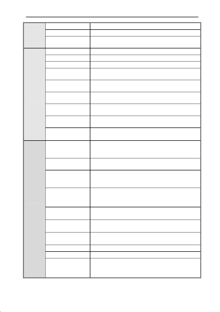
Frequency set channels
Keyboard digital set, keyboard potentiometer, analog voltage terminal VS,
analog voltage/current terminal AI,analog current terminal AS,
communication given and multi channels terminal selection, master-slave
channels combination,expansion card, switch by various modes
Feedback input channel Voltage terminal VS, voltage/current terminal AI ,current terminal AS,
communication given, pulse input PUL.
Running command
channel
Operation panel given, external terminal given, communication
given,expansion card given
Input command signal
Start, stop, FWD/REV, JOG, multi-step speed, free stop, reset,
acceleration/deceleration time selection,frequency given channel
selection, exterior fault alarm.
Exterior output signal
Two relay output, one collector output,one AO output: 0V~10V output or
4mA~20mA output,another AO output: 0V~10V output or 4mA~20mA
output or frequency pulse output.
Protection function
Overvoltage, under-voltage, current limit, over-current, overload, electric
thermal relay,overheat,overvoltage stall,data protection, rapid speed
protection,input/output loss phase protection
Keyboard
display
LED display Single file 5 digital tube display Can monitor one state variable
Two file 5 digital tube display Can monitor two state variables
Parameter copy Can upload or download function code information of inverter to realize
fast parameter copy.
State monitor
Output frequency, given frequency, output current, input voltage, output
voltage, motor speed, PID feedback, PID given value, module
temperature etc monitor parameters..
Fault alarm
Over-voltage, under-voltage, over-current, short circuit, loss phase,
overload, overheat, overvoltage stall, current limit, or data protection
destroyed; Fault running state; Fault history.
Environment
Install place
altitude ≤ 1000m,above 1000m down the rated amount, each increase of
100m down the rated amount of 1%;no condensation,
ice,rain,snow,hail;solar radiation below 700W/㎡, air pressure 70kPa-106
kPa
Temperature,
humidity
-10℃~+50℃, above 40℃ down the rated amount,the maximum
temperature :60℃(no load running),
5%—95%RH(no condensation)
Vibration 9Hz~200Hz,5.9m/s²(0.6G)
Store temperature -30℃~+60℃
Installation Hanging type, cabinet type
Protection degree IP20
Cooling mode Forced cooling

AC200 Frequency Inverter Maunal
5
Chapter 2 Installation
This section specifies the considerations necessary for reliable and safe operation of the product by users.
Overall Dimension of Inverter and Keyboard
W1
W
H1
H
D1
D
MODEL W W1 H H1 D D1
INSTALLATION
APERTURE
AC200-S2-R40G
122 112 182 171 154.5 145 ф5 AC200-S2-R75G
AC200-S2-1R5G
AC200-S2-2R2G 159 147.2 246 236 157.5 148 ф5.5
AC200-T3-R75G
122 112 182 171 154.5 145 ф5 AC200-T3-1R5G
AC200-T3-2R2G
AC200-T3-004G 159 147.2 246 236 157.5 148 ф5.5
AC200-T3-5R5G
AC200-T3-7R5G
195 179 291 275 167.5 158 ф7
AC200-T3-011G
AC200-T3-015G
230 208 330 315 200 190 ф7
AC200-T3-018G
AC200T3-022G

AC200 Frequency Inverter Maunal
6
MODEL Overall Dimension Instillation Position
INSTALLATION
APERTURE
W H D H2 W1 H1
AC200-T3-030G 255 410 225 370 180 395 Ф7
AC200-T3-037G
305 570 260 522 180 550 Ф9 AC200-T3-045G
AC200-T3-055G
AC200-T3-075G
380 620 290 564 240 595 ф11
AC200-T3-090G
AC200-T3-110G
H1
H
H2
D
W1
W
MODEL Overall Dimension Instillation Position
INSTALLATION
APERTURE
W H D H2 W1 H1
AC200-T3-132G 500 780 340 708 350 755 ф11

AC200 Frequency Inverter Maunal
7
AC200-T3-160G
650 1060 400 950 400 1023 ф16
AC200-T3-185G
AC200-T3-200G
AC200-T3-220G
750 1170 400 1050 460 1128 ф18 AC200-T3-250G
AC200-T3-280G
AC200-T3-315G
850 1280 450 1150 550 1236 ф20 AC200-T3-355G
AC200-T3-400G
D1
W 1
D
W
H
H1
MODEL Overall Dimension Instillation Position
INSTALLATION
APERTURE
W H D H1 W1 D1
AC200-T3-160GD
650 1600 400 1500 492 332 ф14 AC200-T3-185GD
AC200-T3-200GD
AC200-T3-220GD
750 1700 400 1600 582 332 ф14 AC200-T3-250GD
AC200-T3-280GD
AC200-T3-315GD
850 1800 450 1700 622 382 ф14 AC200-T3-355GD
AC200-T3-400GD
Notice: DC Reactor Inside

AC200 Frequency Inverter Maunal
8
H
H1
D1
W 1
D
W
MODEL Overall Dimension Instillation Position
INSTALLATION
APERTURE
W H D H1 W1 D1
AC200-T3-450G
1200 1850 550 1750 960 466 ф14 AC200-T3-500G
AC200-T3-560G
MODEL
Overall Dimension Instillation Position
INSTALLATION
APERTURE
W
H
D
H1
W1
D1
AC200-T3-630G 800 1900 700 1800 564 626 ф14
AC200-T3-710G

AC200 Frequency Inverter Maunal
9
Standard Connection Diagram
●
Standard Connection Diagram
Note: 1.When installing DC reactor, make sure to dismantle the short connector between terminal P1 and(+).
2.NPN or PNP transistor signal can be selected as input of multi-function input terminal(X1~X7/PUL).
Inverter built-in power supply (+24V terminal) or external power supply (PLC terminal) can be chosen as
bias voltage. Factory setting ‘+24V’ short connect with ‘PLC’.
3. Analog monitor output is the special output for meters such as frequency meter, current meter and voltage
meter. It can’t be used for control operations such as feedback control.
4. As there are multi pulse styles, please refer to the line connect mode description details.
notice 2
notice:default settings in bracket
notice 1
TA1
TB1
TC1
+24V
Y
shielded twisted pair cable
_
mA
20
10
0
-
+
0
5
10
V
_
+-
GND
A01
V
W
U
M
~
shielded cables
(near inverter groud )
E
(ground resistor low
than 10
Ω
)
W
V
U
output reactor
DC reactor
brake
resistor
short
circuit
P1
+
( )
R
brake module
voltage model analog input
current model analog input
+10V
R
T
S
AC input
AI
GND
AS
VS
shielded twisted pair line)
input pulse
X7
(reversal jog running)
(forward jog running)
(reversal running)
(forward running)
(free stop)
(fault reset)
(none)
COM
X3
X4
X6
X5
X1
X2
PB
( )
+
(-)
inverter
S
T
R
GND
A02
COM
passive terminal output
AC220V
AC0V
K3
K4
max output
3A/240VAC
5A/30VDC
1 +24Vmax output
:
DC24V/100mA
A01/A02 used as frequency or
voltage output
,max current
2mA
2 VS/AIterminal resistor
:
75K
Ω
1.+10V terminals max input 50mA
notice:
2 Y max output
:
DC24V/50mA
notice:
2
stand for control circuit terminal
notice: stand for main circuit terminal
1
shielded twisted pair
cable(near inverter ground)
input reactorconnector
circuit
breaker
(
0~5V
)/(
0~10V
)
(
0~20mA
)/(
4~20mA
)
3 AS terminal resistor
:
250
Ω
notice:
+
( )
notice 4
PUL
X7
PUL
+24V
PLC
COM
current/voltage analog input
J1
J2
J3
K1
K2
K5
K6
TA2
TB2
TC2
AC220V
AC0V
open collector output
A+
B-
RS485 communication
120
Ω
K7
K8
analog output monitor
input terminals
frequency reference input

AC200 Frequency Inverter Maunal
10
●
Auxiliary Terminal Output Capacity
Terminal Function Definition Max Output
+10V 10V auxiliary power supply output, constitutes
loop with GND. 50mA
A01/A02 Analog monitor output, constitutes loop with
GND.
Max output 2mA as frequency,
voltage signal,
+24V 24V auxiliary power supply output, constitutes
loop with COM. 100mA
Y Collector open circuit output; can set the
action-object by program. DC24V/50mA
TA1/TB1/TC1
TA2/TB2/TC2
Passive connector output; can set the
action-object by program.
3A/240VAC
5A/30VDC
●
Connection Function Specification of Switch Terminals
Switch Terminal
Selecting Position
Function Specification
S1 K1 AO1:0 mA~20mA or 4 mA~20mA current output
K2 AO1:0V~10V voltage output
S2 K3 AI:0 mA~20mA or 4 mA~20mA input current
K4 AI: 0V~10V input voltage
S3 K5 AO2: 0.0 kHz~100kHz (J1 on), open collector circuit output
K6 AO2:0.0 kHz~100kHz (J1 on), active source output
S4 K7 RS485: connect with 120Ω terminal resistor
K8 RS485:connect without 120Ω terminal resistor
S5
J1 AO2:0.0 kHz~100kHz frequency output
J2 AO2:0 mA~20mA or 4 mA~20mA current output
J3 0 V~10V voltage output
S6
+24V Short +24V terminal and PLC terminal
PLC PLC terminal receiving external power input
COM Short PLC terminal and COM terminal
S7 K9 Disconnect GND terminal and PE discharge loop
K10 Connect GND terminal and PE discharge loop
AS VS GND
GNDAO2 AO1 X1 X2
AI +10V COM TC1
PLC TA1A+ +24V
X7/PULX4X3 X5 TB2X6 TA2
B- Y TB1
COM TC2

AC200 Frequency Inverter Maunal
11
Chapter 3 Keyboard layout and functions specification
●
Keyboard appearance
●
Key function
Key Name Function
Menu key
Enter menu while standby or running. Press this key to return while
modify parameter. While standby or running, press for 1 sec to enter
condition monitoring interface.
Confirm/modify
key
Press to modify parameter while in menu interface.Press again to confirm
after modifying. While standby or running, press to change LED
monitoring items at stop.
Up/down key
Select parameter group in menu interface. Modify parameter in modify
state. Modify given frequency,PID given while at standby or monitoring
state (While given frequency, PID are set by keyboard and [F4.09] needs
to be set.
Shift key Select digit of function No. modified by up/down key; Select parameter
digits modified by up/down key.
Forward run key
While run/stop is controlled by keyboard, press this key, inverter forward
runs, and the indicator is always on. While reverse, the indicator sparks.
Jog/reverse key
This key can be defined by [F4.07]. Press it, machine reverses and
indicator is off if it is defined as REVERSE. Machine will jog and indicator
is on if it is defined as JOG.
Stop/reset key
Machine stops if press it while run/stop is controlled by keyboard. Its
efficiency range is defined by [F4.08]. Inverter resets if press it in fault
state (no reset if fault is not solved).
Keyboard
potentiometer
Can be used as input channel for given frequency, upper frequency limit,
given torque, given PID or PID feedback setting.
●
Indicator light meanings

AC200 Frequency Inverter Maunal
12
Name State Meaning
Unit indicator
light
Hz Spark/On Frequency unit
A On Current unit
V Spark/On Voltage unit
S On Time unit
RPM On Motor speed unit
% Spark/On Percent unit
State
indicator light
FWD On Forward running
FWD Spark Reverse running
FWD Off Stop
Function
indicator light
REV/JOG On Jog.
REV/JOG Off Reverse.
●
Basic LED operation
It displays frequency 50.00Hz when stop. Here F0.09=100.00 setting will be taken as an example to explain the basic
LED operation.
●
Run monitoring setting

AC200 Frequency Inverter Maunal
13
Chapter 4 Function Parameter Table
This chapter just provides function parameter table.Specifications refer to AC200 technical manual or inquiry the
company.
“●”: Parameter can be changed in the running state.
“〇”: Parameter can’t be changed in the running state.
“×”: Parameter can be read only.
“–”: Factory setting parameter, only factory can set.
“※”: Parameter is related to the model.
4.1 Basic parameters
NO. Function description Range of settings and definition Factory
default
Feature
Address
F0.00 Motor control mode
Asynchronous motor control mode:
0: V/F control
3: High-performance VC without PG
4: High-performance VC with PG
Synchronous motor control mode:
6: High-performance VC without PG
7: VC with PG
Other control:
8:Voltage frequency separation output
1/2/5: Reserved
0 〇 0x000
F0.01 Reserved 0x001
F0.02 Run command channel
0: Keyboard control
1: Terminal control
2: RS485 communication control
3: Optional card
0 ● 0x002
F0.03 Frequency given source
channel A
0: Keyboard number given
1: Keyboard potentiometer given
2: VS voltage analog given
3: AI analog given
4: AS current analog given
5: Terminal pulse PUL given
6: RS485 communication given
7: UP/DW control
8: PID control given
9: Program control (PLC) given
10: Optional card
11: Multi-steps speed given
0 ● 0x003
F0.04 Frequency given source
channel B 1 ● 0x004
F0.05 Frequency channel B
reference source
0: Max. output frequency as reference
source
1: A set frequency as reference source
0 ● 0x005

AC200 Frequency Inverter Maunal
14
F0.06 Frequency given source
selection
0: Channel A
1: Channel B
2: Channel A+Channel B
3: Channel A-Channel B
4: Max. value of Channel A and
Channel B
5: Min. value of Channel A and
Channel B
0 ● 0x006
F0.07 Running command
binding
LED“0”digit: keyboard command
instruction binding
LED“00”digit: terminal command
instruction binding
LED“000”digit: communication
command instruction binding
LED“0000”digit: optional card
command instruction binding
0 : no binding
1 : keyboard number given frequency
2 : Keyboard potentiometer given
3 : VS voltage analog given
4 : AI current/voltage analog given
5 : AS current analog given
6 : Terminal pulse PUL given
7: RS485 communication given
8 : Terminal UP/DW control
9 : PID control given
A: Program control (PLC) given
B: Optional card
C: Multi-speed given
0000 ● 0x007
F0.08 Keyboard number setting
frequency 0Hz~upper limit 50.00Hz ● 0x008
F0.09 Max frequency output upper limit~600.00Hz 50.00Hz 〇 0x009
F0.10 Upper limit frequency
source selection
0: Upper limit frequency digital given
1: Keyboard potentiometer given
2: Terminal VS analog given
3:Terminal AI analog given
4: Terminal AS analog given
5: Terminal pulse PUL given
6: RS485 communication given
7: Optional card
0 ● 0x00A
F0.11 Upper frequency limit
digital setting Lower limit frequency~max frequency
50.00Hz ● 0x00B
F0.12 Lower limit frequency 0.00Hz~upper limit frequency 0.00Hz ● 0x00C
F0.13 Lower limit frequency
running mode
0: Stop output, enter into pause
running state
1: Run at lower limit frequency
1 〇 0x00D

AC200 Frequency Inverter Maunal
15
F0.14 ACC time 1 0.01s~650.00s Model set
※
0x00E
F0.15 DEC time 1 0.01s~650.00s Model set
※
0x00F
F0.16 Rotary direction selection
LED“0”digit: running direction takes
the opposite
0: Direction unchanged
1: Direction takes the opposite
LED“00”digit: running direction
prohibited
0:Forward and reverse commands are
allowed
1: Only FWD command allowed
2: Only REV command allowed
LED“000”digit: frequency control
direction selection
0: Invalid
1: Valid
LED“0000”digit: reserved
0000 〇
0x010
F0.17-F0.18 Reserved
F0.19 Parameter initialization
0: No action
1: Restore factory default (not restoring
motor parameters)
2: Restore factory default (restoring
motor parameters)
3: Clear malfunction records
0 ● 0x013
Run control parameters
NO. Function description Range of settings and definition Factory
setting Feature
Address
F1.00 Start-up mode running
0: Start by start-up frequency
1: Braking first then start by start-up
frequency
2: Speed tracking, judge direction then
start
0 〇 0x100
F1.01 Start pre-excitation time 0.00s~60.00s 0.00s
〇 0x101
F1.02 Start-up frequency 0.00Hz~60.00Hz 0.50Hz 〇 0x102
F1.03 Start-up frequency
holding time 0.0s~50.0s 0.0s 〇 0x103
F1.04 Braking current before
start 0.0%~150.0% 60.0% 〇 0x104
F1.05 Braking time before start 0.0s~60.0s 0.0s 〇 0x105
F1.06 Speed tracking speed 0.00s~60.00s 0.50s
〇 0x106
F1.07 Speed tracking stop
delay 0.00s~60.00s 1.00s
〇 0x107
F1.08-F1.09 Reserved 0x108

AC200 Frequency Inverter Maunal
16
F1.10 Stop mode 0: DEC stop
1: Free stop 0 ● 0x10A
F1.11 DC braking initial
frequency when stop 0.00Hz~50.00Hz 1.00Hz 〇 0x10B
F1.12 DC braking current when
stop 0.0%~150.0% 60.0% 0x10C
F1.13 Reserved
0x10D
F1.14 DC braking holding time
when stop 0.0s~60.0s 0.0s 〇
0x10E
F1.15 Detection frequency
when stop 0.00Hz~50.00Hz 0.50Hz ●
0x10F
F1.16 ACC/DEC selection
LED “0” digit: time base selection
0: max frequency
1: fixed frequency 50Hz
2: set frequency
LED “00” digit: S ACC/DEC
selection
0: Beeline ACC/DEC
1: S Curve ACC/DEC
LED“000/0000”digit: reserved
LED “0000” digit: reserved
0010 〇 0x110
F1.17 ACC start S curve time 0.00s~10.00s 0.10s 〇 0x111
F1.18 ACC finish S curve time 0.00s~10.00s 0.10s 〇
0x112
F1.19 DEC start S curve time 0.00s~10.00s 0.10s 〇
0x113
F1.20 DEC finish S curve time 0.00s~10.00s 0.10s 〇 0x114
F1.21 ACC time 2 0.01s~650.00s 10.00s ● 0x115
F1.22 DEC time 2 0.01s~650.00s 10.00s ● 0x116
F1.23 ACC time 3 0.01s~650.00s 10.00s ● 0x117
F1.24 DEC time 3 0.01s~650.00s 10.00s ● 0x118
F1.25 ACC time 4 0.01s~650.00s 10.00s ● 0x119
F1.26 DEC time 4 0.01s~650.00s 10.00s ● 0x11A
F1.27 Emergency stop DEC 0.01s~650.00s 1.00s ● 0x11B
F1.28 FWD&REV dead time 0.0s~120.0s 0.0s 〇
0x11C
F1.29 Zero speed torque
frequency threshold 0.00Hz~10.00Hz 0.50Hz ●
0x11D
F1.30 Zero speed torque
holding coefficient 0.0%~150.0% 60.0%
●
0x11E
F1.31 Zero speed torque
holding time
0.0s~6000.0s
If set 6000.0s, always hold 0s ● 0x11F
F1.32-F1.34 Reserved
0x120
F1.35 Power off restart action
selection
0: Invalid
1: Valid 0 〇
0x123

AC200 Frequency Inverter Maunal
17
F1.36 Power off restart waiting
time 0.00s~60.00s 0.50s 〇
0x124
F1.37 Reserved
0x125
F1.38 JOG running frequency
setting 0.00Hz-Max frequency 5.00Hz ●
0x126
F1.39 JOG ACC time 0.01s~650.00s 10.00s ●
0x127
F1.40 JOG DEC time 0.01s~650.00s 10.00s ● 0x128
F1.41 Jump frequency 1
0.00Hz
~
Max frequency
0.00Hz ● 0x129
F1.42 Jump frequency range 1
0.00Hz
~
Max frequency
0.00Hz ● 0x12A
F1.43 Jump frequency 2
0.00Hz
~
Max frequency
0.00Hz
● 0x12B
F1.44 Jump frequency range 2
0.00Hz
~
Max frequency
0.00Hz
● 0x12C
Quantum Digital Terminal Parameter Group
NO. Function description Range of settings and definition Factory
setting Feature
Address
F2.00 Multifunction input
terminal 1(X1)
Refer to 4.2 Function Selection Table
1 〇 0x200
F2.01 Multifunction input
terminal 2(X2) 2 〇 0x201
F2.02 Multifunction input
terminal 3(X3) 4 〇 0x202
F2.03 Multifunction input
terminal 4(X4) 5 〇 0x203
F2.04 Multifunction input
terminal 5(X5) 6 〇 0x204
F2.05 Multifunction input
terminal 6(X6) 8 〇 0x205
F2.06 Multifunction input
terminal 7(X7/PUL) 0 〇
0x206
F2.07 Reserved 0 〇
0x207
F2.08 X1-X4 terminal trait
selection
0: On valid 1: Off valid
LED “0” digit: X1 terminal
LED “00” digit: X2 terminal
LED “000” digit: X3 terminal
LED “0000” digit: X4terminal
0000 ●
0x208
F2.09 X5-X7 terminal trait
selection
0: On valid 1: Off valid
LED “0” digit: X5 terminal
LED “00” digit: X6 terminal
LED “000” digit: X7 terminal
LED “0000” digit::reserved
0000 ●
0x209
F2.10 X1 valid detection delay 0.000s~6.000s 0.010s ● 0x20A
F2.11 X1 invalid detection delay
0.000s~6.000s 0.010s ● 0x20B
F2.12 X2 valid detection delay 0.000s~6.000s 0.010s ● 0x20C
F2.13 X2 invalid detection delay
0.000s~6.000s 0.010s ● 0x20D

AC200 Frequency Inverter Maunal
18
F2.14 X3 valid detection delay 0.000s~6.000s 0.010s ● 0x20E
F2.15 X3 invalid detection delay
0.000s~6.000s 0.010s ● 0x20F
F2.16 X4 valid detection delay 0.000s~6.000s 0.010s ● 0x210
F2.17 X4 invalid detection delay
0.000s~6.000s 0.010s ● 0x211
F2.18 X5 valid detection delay 0.000s~6.000s 0.010s ● 0x212
F2.19 X5 invalid detection delay
0.000s~6.000s 0.010s ● 0x213
F2.20 X6 valid detection delay 0.000s~6.000s 0.010s ● 0x214
F2.21 X6 invalid detection delay
0.000s~6.000s 0.010s ● 0x215
F2.22 X7 valid detection delay 0.000s~6.000s 0.010s ● 0x216
F2.23 X7 invalid detection delay
0.000s~6.000s 0.010s ● 0x217
F2.24-F2.25 Reserved 0x218
F2.26 Terminal control running
mode
0: 2-line 1
1: 2-line 2
2: 3-line 1
3: 3-line 2
0 〇 0x21A
F2.27 Terminal operation
protection
0: OFF 1:ON
LED “0” digit: Terminal operate
protection when abnormal exit
LED “00” digit: Jog terminal operate
protection when abnormal exit
LED “000” digit: Operate protection
when command channel switched to
terminal
LED “0000” digit: reserved
0111 〇
0x21B
F2.28 Counter input source
0: Normal X terminal
1:High speed input terminal PUL
2:PG card counting value
0 ● 0x21C
F2.29 Counter input frequency
division 06000 0 ● 0x21D
F2.30 PUL input min frequency 0.00kHz~50.00kHz 0.00kHz ●
0x21E
F2.31 PUL min frequency
corresponding setting 0.00%~100.00% 0.00% ●
0x21F
F2.32 PUL input max frequency 0.00kHz~50.00kHz 50.00kHz
●
0x220
F2.33 PUL max frequency
corresponding setting 0.00%~100.00% 100.00% ●
0x221
F2.34 PUL filter time 0.000s~9.000s 0.100s ●
0x222
F2.35 PUL cut-off frequency 0.000kHz~1.000kHz 0.010kHz
●
0x223
F2.36 UP/DW terminal control
mode
0: Off electricity storage
1: Off electricity not storage
2: Valid in running, clear zero at stop
0 〇
0x224
F2.37
ACC/DEC speed of
UP/DW terminal
controlling frequency
0.01Hz/s~50.00Hz/s 0.50Hz/s ●
0x225
F2.38 Reserved 0x226
This manual suits for next models
43
Table of contents
Other Veichi Inverter manuals

Veichi
Veichi SI30 series User manual

Veichi
Veichi AC70T series User manual

Veichi
Veichi AC70 series User manual

Veichi
Veichi AC200-L Series User manual

Veichi
Veichi AC10 Series User manual

Veichi
Veichi SD700-1R1A series User manual

Veichi
Veichi SI23-D1 series User manual

Veichi
Veichi AC100-T3-1R5G User manual

Veichi
Veichi SI22 series User manual

Veichi
Veichi SI30 series User manual