Lumel PD15 User manual

1
PROGRAMMER
FOR N15, N15Z, N17Z
DIGITAL METER SERIES
and
P15, P16 TRANSDUCERS
USER’S MANUAL

2

3
CONTENTS Page
1. APPLICATION ..............................................................................5
2. PROGRAMMER SET ...................................................................5
3. REQUIREMENTS .........................................................................5
4. OPERATIONAL SAFETY .............................................................5
5. SOFTWARE INSTALLATION .......................................................6
6. PROGRAMMER CONNECTION TO THE METER ......................6
7. DESCRIPTION OF THE PD15 PROGRAM .................................9
7.1. Programming of N15 meter.................................................10
7.2. Label of N15 meter.............................................................. 11
7.3. Calibration of N15 meter .....................................................12
7.4. Programming of N15Z and N17Z meters ............................12
7.5. Label of N15Z and N17Z meters.........................................14
7.6. Calibration of N15Z and N17Z meters ................................15
7.7. Programming of P15 transducer .........................................15
7.8. Label of P15 transducer ......................................................16
7.9. Calibration of P15 transducer..............................................18
7.10.Programming of P16 transducer .........................................18
7.11. Label of P16 transducer ......................................................19
7.12.Calibration of P16 transducer..............................................20
8. TECHNICAL DATA .....................................................................20
9. MESSAGES ABOUT ERRORS ..................................................21
10. MAINTENANCE AND GUARANTEE ..........................................22
PROGRAMMER
FOR N15, N15Z, N17Z DIGITAL METER SERIES
and P15, P16 TRANSDUCERS
April 2007 - KZ 1362/07
USER’S MANUAL

4

5
1. APPLICATION
The PD15 programmer is destined to program meters of N15 , N15Z, N17Z digital
meter series, P15 and P16 transducers in the windows 9x/2000/NT/XP environ-
ment.
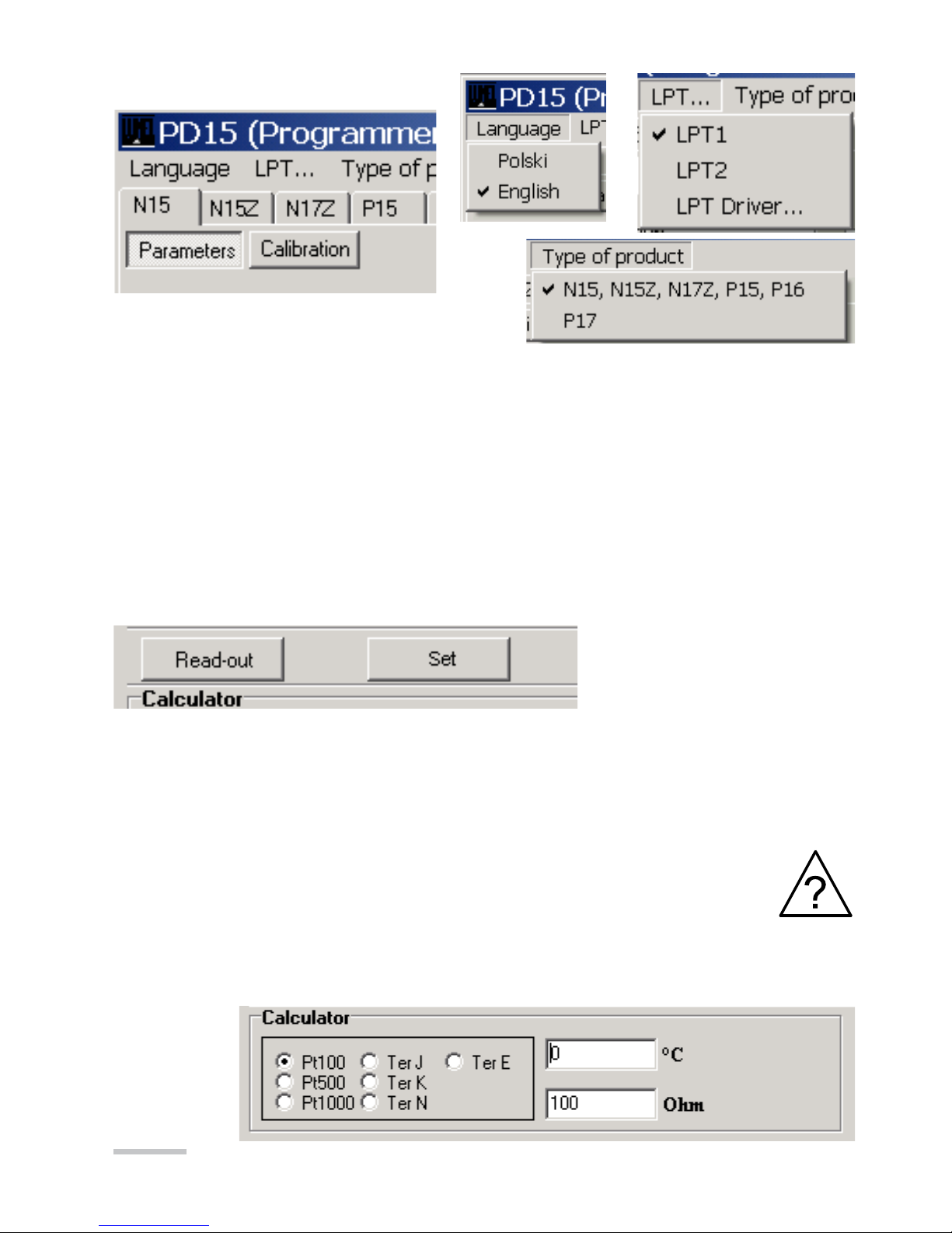
The programmer enables:
zmianê parametrów mierników i przetworników,
kalibracjê mierników i przetworników.
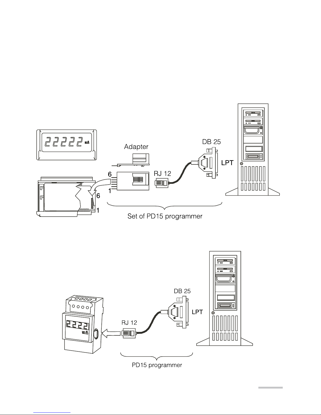
2. PROGRAMMER SET
The PD15 programmer set is composed of:
- PD15 programmer 1 pc
- Mini CD Diskette with software 1 pc
- Adapter plate 1 pc
- User’s manual 1 pc
- Guarantee card 1 pc
When unpacking the programmer, please check whether the type and execution
code on the plate correspond to the order code.
3. REQUIREMENTS
- Windows 9x/2000/NT/XP
- Ca 2 MB of empty place on the disk
- Minimum 4 MB RAM memory
- LPT port with the possibility of working in the SPP, EPP or EPP/ECP mode
4. OPERATIONAL SAFETY
Symbols included in this user’s manual mean:
- Particularly important, one must acquaint with it before connecting the
programmer. The non-observation of remarks determined by this symbol
can cause the programmer or meter damage.
- One must take into consideration when the programmer is working
inconsistently with expectations.
Remarks related to the safety:
- The meter reprogramming should be carried out only by an authorised and quali-
fied personnel.
- Before the meter reprogramming one must check the correctness of the program-
mer connection with the meter.
- During the meter reprogramming one must remember about the high voltage being
on the meter power pack elements. Please observe particular caution. Possible
consequence if disregarded.

6
5. SOFTWARE INSTALLATION
For a correct operation of the PD15 programmer, it is necessary to install the work
of the LPT port in the SPP, EPP or EPP/ECP mode.
Caution!
In case of the LPT port working in the ECP mode or in case of some main plates
in EPP/ECP mode, the PD15 programmer will not work correctly.
One can modify the setting of the LPT port working mode in the computer BIOS, in
the „Integrated peripherals” properties.
In order to install the PD15 program, one must:
1. Introduce the installation mini CD diskette into the disk station, e.g. d:\
2. Click the start key on the windows task bar and choose Start...
3. Write the access path, e.g. d:\setup.exe
After starting the installation program, define the in-coming path, e.g. C:\Program
Files\LZAE LUMEL S.A.\Programator PD15 and the working group, e.g.: LZAE
LUMEL S.A.
6. DESCRIPTION OF THE PD15 PROGRAM
The PD15 program realises following functions:
- programming - where it is possible to reprogram meter/transducer parameters,
- calibration (after giving the calibration password) - which enables the meter/
transducer calibration or its recalibration.
Fig. 1. Installation window of the LPT port driver

7
Fig. 2. Program main window
The program start follows after clicking the “PD15” program icon in
the “LZAE LUMEL SA” group. After starting, the program works in the
edition mode. The main program window is shown on the fig. 2.
Caution!
In case of the program start for the first time, one must install the LPT “ DL Port I0”
parallel port driver. For this aim, one must choose ”LPT …” -> “LPT Driver...” and
next proceed according the description.
The installation program window of the LPT port driver is shown on the Fig. 1.

8
- The language enables the work in one of the two language versions: Polish or
English.
- The “LPT “ program menu enables the selection of the LPT (LPT1, LPT2) parallel
port and the installation of the LPT port driver (LPT Driver...).
- Type device enables the selection of devices of series N15, N15Z, N17Z, P15,
P16 or P17. The setting of programmable parameters or P17 calibration can be
carried out after the password write.
Program menu:
Readout and recording of parameters into the meter
Calculator
Keys “Read out” and “Write”
serve for readout and record-
ing of meter parameters.
The “Write” key activates
Caution!
The operation failure of meter parameter readout is signalled by the mes-
sage about error. See p.9 “Messages about errors”
itself only when follows the readout of parameters from the meter after the first
program start. It secures the meter against the discalibration and recording of er-
roneous meter parameters. The correct readout of parameters from the meter is
signalled by the message: “ Programming/readout favourably ended”.

9
Fig. 3. Programmer connection with N15, N15Z meters and the computer.
Fig. 4. Programmer connection with N17Z meter and the computer.
In order to facilitate the user the recount of the resistance or the thermoelectric volt-
age into temperature, the program is equipped with a simple recounting calculator for
sensor used in N15 meters In case of calculations for thermocouples, the calculator
also takes into consideration the sensor temperature of meter terminals.
7. PROGRAMMER CONNECTION TO THE METER
The connection of the programmer with meters and the PC computer is presented
on fig. 3 and 4. Before programming, one must remove the meter housing.

10
Measurement time -
Measurement averaging time.
W przetworniku P15 gniazdo programatora umieszczone jest wewnątrz obudowy.
W celu przeprogramowania należy zdjąć obudowę i na części czołowej przetwor-
nika umieszczone jest gniazdo typu RJ.
W przetworniku P16 gniazdo programatora umieszczone jest wewnątrz obudowy.
W celu przeprogramowania należy odkręcić 4 wkręty na pokrywie czołowej i zdjąć
obudowę. Na płytce umieszczono 6 pól do podłączenia programatora PD15 z wy-
korzystaniem dołączonej przejściówki RJ-piny.
7.1. Programming of N15 meter
Parameter programming
Compensation - Compensation kind of the meter
working condition changes
Manual compensation:
Introduce the wire resistance value linking the sen-
sor to the meter (in the case of a meter with RTD
sensor) or the value of the ambient temperature (in
case of a meter with a thermocouple).
Automatic compensation:
- In case of a resistance thermometer and resistance measurement, concerns the
compensation of resistance changes of wires linking the sensor with transducer.
It requires a 3-wire line.
- In case of a thermocouple, concerns the compensation of reference junction
temperature changes.
The automatic compensation does not operate in case of a 4000 Ω potentiometer
transmitter or RTD Pt500, Pt1000.
Unit highlighting -
Switching on or off the highlighting of the unit
in the meter (only for meters with a 5-digit
display)

11
Decimal point -
Setting of the decimal point.
Programming of the indication range
In order to reprogram the indi-
cation range one must set the
indication range programming
on “enabled”. Next, one must
set to which values measured
on the input (X1, X2) have to
correspond values displayed
on the display (Y1, Y2).
The programming of the indication
range gives the possibility of a quick
and easy change of the displayed
value on the display.
On the base of given co-ordinates
of two points by the user, the me-
ter assigns aand b. (Y1=a.X1+b,
Y2=a.X2+b).
7.2. Label of N15 meter
In case of meter reprogramming, one must fill in the label, writing in their fields the
appropriate work parameters of the meter. The label of the N15 meter is shown
on the Fig. 5.
Fig. 5. View of the N15 meter label.

12
Field Nr 1. One must write the meter working range in,
and the unit of the input channel.
Field Nr 2. One must write the meter indication range.
Field Nr 3. One must write the kind of compensation of the sensor work
condition changes (only in the case of a temperature meter).
In case of a manual compensation:
- for resistance thermometers: in „„, e.g.: 15 (this is the total resistance of
two wires connecting the sensor with the meter),
- for thermocouples, value in „°C”, np.: 25°C (this is the temperature of terminals),
In case of an automatic compensation one must write auto in. In this case the
meter will compensate automatically:
- in case of resistance thermometers - the wire resistance change,
- in case of thermocouples - the terminal temperature change.
7.3. Calibrtion of the N15 meter
The N15 calibration window is accessible after selecting the “calibration” tag and
writing the calibration password (option accessible only in service workshops).
Recovery of calibration coefficients
In case of a meter erroneous calibration, there is the
possibility to recover calibration coefficients written by the
meter Manufacturer during the meter calibration. We can
do this by pressing the Save… button.
7.4. Programming of N15Z and N17Z meters
Parameter programming
N15Z
N17Z
Selection of the meter working mode.
AC:
In this mode the meter measure only the
variable component
AC+DC:
In this mode the meter measure the variable
component together with the constant compo-
nent. Measurement of TrueRMS.
DC:
Accessible only in N17Z. In this mode, the
meter measure only the constant component.

13
Unit highlighting
Switching on or off the highlighting of the unit in
the meter
N15Z – only for meters with a 5-digit display.
N17Z – all versions
In N15Z meters with a 4-digit display, the change
of this parameter does not influence its work.
Measurement time -
Measurement averaging time.
Decimal point -
Setting of the decimal point.
Programming of the indication range
The programming of the indication
range gives the possibility of a quick
and easy change of the displayed
value on the display.
On the base of given co-ordinates
of two points by the user, the me-
ter assigns aand b. (Y1=a.X1+b,
Y2=a.X2+b).
In order to reprogram the indication
range one must set the indication
range programming on “enabled”.
Next, one must set, to which values
measured on the input (X1, X2) have
to correspond values displayed on
the display (Y1, Y2).

14
Fig. 6. View of the N15Z meter label
7.5. Label of N15Z and N17Z meters
In case of meter reprogramming, one must fill in the label, writing in their fields the
appropriate work parameters of the meter.
The label of the N15Z and N17Z meters are shown on Fig. 5. and fig. 6.
Fig. 7. View of the N17Z meter label
Field Nr 1. One must write the meter working range in, and the unit of the input
channel.
Field Nr 2. One must write the meter indication range.

15
7.6. Calibration of N15Z and N17Z meters
The N15Z and N17Z calibration window is accessible after selecting the
“calibration” tag.
Recovery of calibration coefficients
In case of a meter erroneous calibration, there is the pos-
sibility to recover calibration coefficients written by the meter
Manufacturer during the meter calibration. We can do this
by pressing the Save… button.
7.7. Programming of the P15 transducer
Parameter programming
Input type – Kind of input depending on the
version of the P15 transducer (measured
Signal)
Selection of the type input: J, K, N, E, mV
- appears in the case of versions: P15-01X,
P15- 02X, P15-03X, P15-04X, P15-09X.
Selection of the type input: Tempera-
ture,
Resistance - appears in the case of
versions: P15- 05X, P15-06X, P15-07X,
P15-08X.
Compensation – Kind of compensation of
transducer work condition changes.
Manual compensation:
Introduce the wire resistance value linking
the sensor to the transducer (in the case
of a transducer with RTD sensor) or the
value of the ambient temperature (in case
of a transducer with a thermocouple).

16
Automatic compensation:
- In case of a resistance thermometer and
resistance measurement, concerns the
compensation of resistance changes of
wires linking the sensor with the transducer.
It requires a 3-wire line.
- In case of a thermocouple, concerns the
compensation of reference junction tem-
perature changes.
Conversion time – Averaging time,
conversion.
The programming of the indication
range gives the possibility of a quick
and easy change of the displayed
value on the display. On the base
of given co-ordinates of two points
by the user, the transducer as-
signs aand bcoefficients of the
individual characteristic. (Y1=a.X1+b,
Y2=a.X2+b).
Programming of the indication range
7.8. Label of P15 transducer
In case of transducer reprogramming, one must fill in the label, writing in their fields
the appropriate work parameters of the transducer.
The label of the P15 transducer is shown on the Fig. 8.
Field Nr 1. One must mark the suitable thermocouple or RTD.
Field Nr 2. One must write the kind of compensation of the sensor work condition
changes.
In case of a manual compensation:
- for resistance thermometers: in „Ω”, e.g.: 15 Ω (this is the total resistance of two
wires connecting the sensor with the meter),
- for thermocouples, value in „oC”, e.g.: 25oC(this is the temperature of terminals),
In order to reprogram the indication range one must set to which values measured
on the input (X1, X2) have to correspond values displayed on the display (Y1,
Y2).

17
Fig. 8. View of the P15 transducer labels
In case of an automatic compensation one must write auto in.
In this case the meter will compensate automatically:
- in case of resistance thermometers - the wire resistance change,
- in case of thermocouples - the terminal temperature change of terminals.
1
2
1
2

18
7.9. Calibration of P15 transducer
The calibration window of P15 transducer is accessible after selecting the „Calibra-
tion” tag and writing and acceptation the calibration password (option accessible
only in authorized workshops).
In case of a transducer erroneous calibration, there
is the possibility to recover calibration coefficients
written by the transducer Manufacturer during the
transducer calibration. We can do this by pressing
the Save… button.
Recovery of calibration coefficients
7.10. Programming of the P16 transducer
Parameter programming
Output OC type – Accessible only in
the case of a version with OC.
OC type – allows to select: Normal,
Enabled, Disabled, Manually ena-
bled, Manually disabled.
Input type - Temperature or humidity
PrL OC – temperature or humidity
lower threshold, depending on the
selected input type.
PrH OC – temperature or humidity
upper threshold, depending on the
selected input type.
Programming of the indication range
The programming of the conversion range gives the possibility of a quick and easy
change of the displayed value on the display.
On the base of given co-ordinates of two points by the user, the transducer assigns
a and b coefficients of the individual characteristic. (Y1=a.X1+b, Y2=a.X2+b).
Conversion time – Averaging time,
conversion.

19
In order to reprogram the conversion range, one must set to which values meas-
ured on the input (X1, X2) have to correspond values displayed on the display
(Y1, Y2).
The programming of the Humidity conversion Range is accessible only in the ver-
sion P16-W
7.11. Label of the P16 transducer
Labels of the P16 transducer are shown on the Fig. 9.
Fig. 9. View of the P16 transducer labels

20
7.12. Calibration of the P16 transducer
The calibration window of the P16 transducer is accessible after the selection of the
“Calibration” tag, write and acceptation of the correct calibration password
(This option is accessible only in service workshops).
In case of a transducer erroneous calibration, there is
the possibility to recover calibration coefficients written
by the transducer Manufacturer during the transducer
calibration.
We can do this by pressing the Save… button.
Recovery of calibration coefficients
8. TECHNICAL DATA
Galvanic isolation 4000 V d.c.
Rated operation conditions:
- supply voltage collect from the meter
- ambient temperature -20…23…60oC
- storage temperature -20…+85oC
- air relative humidity <95% (condensation inadmissible)
- working position any
Communication parameters:
- data transmission through LPT link
Assured protection degree IP 00
Dimensions DB25 housing
Wire length 1.5 m
Electromagnetic compatibility:
- immunity EN 61000-6-2
- emission EN 61000-6-4
Safety requirements: Acc. EN 61010-1 standard
Table of contents
Other Lumel Motherboard manuals