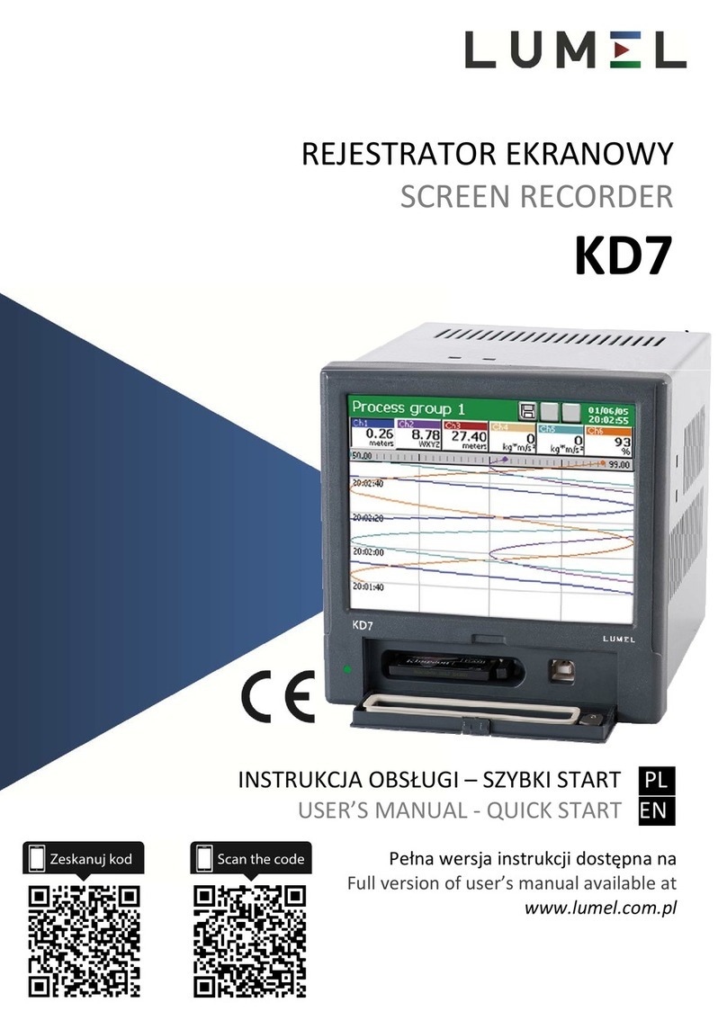
Lumel KD7 User manual

SCREEN RECORDER
KD7 TYPE
USER’S MANUAL

2
Contents
1. INTRODUCTION…………………………………………………………….…………….
4
1.1 Recorder applications ..................................................................................…….... 4
1.2 Recorder features ......................................................................................………... 4
2. GENERAL INFORMATION.................................................................................….
5
2.1 Warning and information signs ..................................................................…….….. 5
2.2 Safety of service .......................................................................................…..…….. 5
2.2.1 Remarks concerning the recorder installation...........................................……….… 5
2.2.2 Precautions in the scope of ESD protection………………………………………..…. 6
3. RECORDER PREPARATION TO WORK......................................................…….. 6
3.1 Unpacking ...................................................................................................…….….
6
3.2 Installation in a panel ……....................................................................................… 8
3.3 Operating conditions of the recorder…….............................................................… 8
4. RECORDER CONSTRUCTION……........................................................................
8
4.1 LCD screen with touch panel …….....................................................................….. 9
4.2 CompactFlash memory card, USB interface, LED diode....................................….. 10
4.3 Terminal plate ..................................................................................................……. 12
4.3.1 Connection of analog signals…….. .................. ..............................................……. 13
4.3.1.1 Standard measuring systems AI 1..12........................................................……...... 13
4.3.1.2 Programmable measuring systems AI 1..12....................................................…..... 13
4.3.1.3 Analog output systems AO 1..8.................................................................…….…… 14
4.3.2 Connection of digital signals.....................................................................……….… 15
4.3.2.1 Alarm systems AL 1...32 and binary inputs BI 1..16 ....................................……… 15
4.3.2.2 Interfaces RS485(1), RS485(2), RS232, Ethernet 10-Base-T ................................ 16
4.3.3 Recorder supply (a.c. or d.c.) ....................................................................………… 17
5. GRAPHICAL SIGNS ON THE RECORDER SCREEN ………...........................…. 17
5.1 Status bar ................................................................................................................ 17
5.2 Measuring views…................................................................................................…
17
5.3 Service menu ........................................................................................................... 18
5.4 Information messages. …. ....................................................................................... 18
5.5 Dialogues.................................................................................................................. 19
6. STARTING THE RECORDER..............................................................................… 19
6.1 Context menu …………………………………………………………………….........… 20
6.2 Entry into the recorder parameter configuration, “KD7 control panel “ window…… 22
7. CONFIGURING THE RECORDER....................................................………….…… 23
7.1 General settings ............................................................................................……… 24
7.2 Ethernet ................................................................................................................... 25
7.3 Modbus .................................................................................................................... 25
7.4 Safety....................................................................................................................... 26
7.5 System information .............................................................................................… 27
7.6 Alarm and analog outputs ………………………………………………………………. 28
7.7 CF card.................................................................................................................…
29
7.8 Configuration, visualization and archiving of the channel group……………………. 30
7.9 Context menu ............................................................................................……….. 31
7.10 Inputs (logic channels)….. ....................................................................................... 32
7.10.1 Definition of logic channel .................................................................................…... 33
7.10.2 Menu of logic channel programming ……..........................................................….. 35
7.10.3 Selection and configuration of the input for a logic channel..............................….. 37
7.10.3.1 Modbus Master Input CI 1..24 ..................................................................…........... 37
7.10.3.2 Analog input AI 1..16...........................................................................….…............ 39
7.10.3.3 Mathematical functions MT 1..16, activation of the access..................................... 43
7.10.3.4 Binary input BI 1..16 …………..……….……………………………………………….. 49
7.10.3.5 Alarm of the logic channel 1…32……………………………………………………….. 50
7.10.3.6 Totalizer of the logic channel 1…32……………………………………………………. 50
7.11 Configuration and service of event logs…………………………...…………………… 51
7.11.1 Review and service of event logs……………………………………………………... 52

3
7.11.2 Programming of event logs……………………………………………………………… 53
7.12 Edition of operator messages………………………………………………………….. 55
7.13 Exit from the recorder configuration……………..………………………………..……. 57
8. SELECTED ELEMENTS OF THE RECORDER CURRENT SERVICE.................. 58
8.1 CompactFlash memory card ……...................................................................……. 58
8.1.1 Information about the CF memory card.................................................................... 58
8.1.2 Formatting the CF card.....................................................................................…… 58
8.1.3 Data storage on the CF card (card storage capacity)……………………..........……. 59
8.1.4 Visualization of the CF card state on the screen ……..........................................… 61
8.1.5 Review and erasing of files from the CF card.......................................................... 61
8.1.6 Removal/replacement of the CF card, storage of archive data……………............ 62
8.2 Programming of logic channel groups 1…4 ………………………………………….. 63
8.2.1 Programming group parameters ……..................................................................…. 64
8.2.2 Digital view of the channel group......................................................................….... 66
8.2.3 Linear chart of the channel group........................................................................…. 67
8.2.4 View of the channel group in the form of bargraphs ……........................................ 69
8.2.5 Analog view of the channel group.....................................................................…… 70
8.2.6 Statistic view of the channel group.......................................................................… 71
8.2.7 Enabling/Disabling of the screen automatic switching in the group......................... 72
8.2.8 Zoom scale function of the signal (measuring magnifier)…………......................…. 73
8.3 Selection of the measuring data file format (digital signature)…………….........…... 74
8.4 Structure of the data flow in KD7 recorder..................................................…….….. 75
8.5 Programming logic channel parameters….............................................…………... 77
8.5.1 Programming General, Visualization and Common parameters………………….… 77
8.5.2 Programming the Logic channel alarm………………………………………………... 79
8.5.3 Programming Totalizer parameters (Counter/Integral)……...……………………..… 83
8.5.4 Programming of parameters (Common)……………………………………………….. 86
8.5.5 Totalizer control ( Counter/Integral)…………………………………………………….. 87
8.6 Programming outputs……………………………………………………………………. 88
8.6.1 Programming analog outputs……........................................................................... 88
8.6.2 Programming alarm outputs…………………………………………………………….. 88
8.7 Edition of recorder users …………………………………………………………….… 90
8.8 Review of archived data ……………....................................................................… 91
8.9 Calibration of the touch screen.............................................................................… 92
8.10 Updating of the recorder software............................................................................ 93
8.11 Service of data stored on the CF card, visualization…............................................ 94
9. PROGRAMS ON PC.........................................................................……............... 95
9.1 KD Connect program............................................................................................. 95
9.1.1 Installation of drivers for the KD7 recorder ..........................................................… 95
9.1.2 Installation of the KD Connect program ...........................................................…. 96
9.1.3 Program service….................................................................................................... 98
9.1.4 Example of using the KD Connect program ……………...................................…. 102
9.1.5 Error messages…….............................................................................................… 104
9.2 KD7 Setup program................................................................................................. 104
9.2.1 Installation................................................................................................................ 104
9.2.2 Program service………………………………………………………………………….. 105
9.3 KD Check program ………..................................................................................... 107
9.4 KD Archive program……………………………………………………………………. 108
9.5 Service of the WWW server ................................................................................... 108
9.5.1 General view.........................................................................................................… 109
9.5.2 View of the window to browse data from the CF card .....................................……. 109
9.5.3 View of the window with information about the KD7 recorder….……………………. 110
9.5.4 Configuration.........................................................................................................… 110
9.5.5 Symbols of the KD7 recorder on the web page........................................................ 111
9.5.6 Firmware update thru the device web page 111
9.5.7 FTP Download Application 113
10. TECHNICAL DATA ...........................................................................................…..
114
11. ORDER CODES............................................................................……...........…….
118
12. MAINTENANCE AND GUARANTEE…………….……….………………………….. 119

4
1. INTRODUCTION
1.1 RECORDER APPLICATIONS
The KD7 screen recorder is applied as a data acquisition station in measuring and control systems.
It finds application to measure, visualize and supervise technical process parameters in various
industrial branches, e.g. pharmacy, food, chemical and papermaking industries.
It can be also used as an autonomous measuring and recording device.
The KD7 screen recorder is adapted to measure voltage, current, temperature, resistance changes
and other quantities converted into a signal or electrical parameter. The source of measuring data
can be also communication interfaces (ETHERNET, RS-485).
All processes suitable for a measuring system can be realized in this recorder: measurement of input
signals and their conversion, visualization and archiving of data, signaling and communication with
the environment.
Converted measuring data are stored in the internal memory and on the CompactFlash card.
1.2. RECORDER FEATURES
▪LCD TFT 5.7” colour screen, 320 x 240 pixels, with a touch panel for the recorder service,
▪Exchangeable CompactFlash internal memory with capacity from 16 MB up to 4 GB,
▪Communication interfaces: Ethernet 10 Base-T, USB 1.1 Device, RS-485 Modbus Slave
and Master, RS-232,
▪Measuring inputs for the direct connection of thermocouples, voltage, current and resistance,
▪Analog outputs, alarms, binary inputs,
▪Mathematical functions, counters and totalizers, operator messages.
▪Digital signature for archived data, stored in textual or binary format,
▪Visualization and archiving of measuring data transmitted to the recorder from other devices
through the RS-485 Modbus Master interface or Ethernet,
▪Linearization of sensor characteristics,
▪Programmable current, voltage and resistance inputs,
▪Copying of parameter setting between channels,
▪Programming of recorder parameters,
▪Programming of screens and choice of screen configurations,
▪Storage of data in the internal 6 MB buffer with data support (for before damage and after
damage states)
▪Structure programming of functions converting measuring quantities into output quantities
and structures of alarm functions, destined to be exposed on the screen and written on
the data carrier,
▪Determination of the set of data for the current exposition on the screen,
Choice of the time zone, automatic change of summer/winter time, synchronization with a time
server.
Note: The update for the KD7 recorder software is available on the page:
http://www.lumel.com.pl

5
2. GENERAL INFORMATION
2.1 Warning and information signs
One or more of presented symbols can be used in the recorder.
Caution: one must pay attention to the description in the
recorder user’s manual.
Terminal of the protection lead
Earth terminal
Protection of sensitive electrostatic systems (ESD)
2.2 Safety of service
The KD7 recorder fulfils requirements related to safety of electrical measuring instruments for
automation, acc. to EN 61010-1 standard and requirements concerning the resistance against
interference occurring in industrial environment acc. to EN 61000-6-2 and EN 61000-6-4 standards.
The connection of supply, communication interfaces and measuring signals, and the use of
equipment inconsistent with the description included in the present user’s manual and standards as
above can cause serious weakening of the recorder protection against interference.
2.2.1 Remarks concerning the recorder installation
Various sources of interference occurring in practice, interact with the recorder in a continuous
or impulse way from the supply network side (as the result of the action of other devices) and also
overlap on the measured signal or auxiliary circuits of the recorder.
In particular, strong impulse interference is dangerous for the operation of devices since they
can cause sporadic erroneous measurement results or accidental operations of alarms, despite of the
use of suitable filters in the recorder. The level of this interference should be reduced to a value
lower than the resistance threshold of the recorder, first of all through a suitable installation of the
recorder in the object.
In this scope, it is recommended to observe following recommendations:
•Do not supply recorders from networks near devices generating high impulse interference in the
supply network and do not use common grounding circuits with them,
•Use network filters for the group of recorders servicing the same object,
•Use metallic shields in the shape of tubes or braids to lead supplying wires (phase, zero), in
which one can also lead the earth conductor and eventually network wires supplying contacts
of alarm relays of the given recorder,
•Lead individually connections of binary input circuits in shields as above, by means of twisted
wires,

6
•Lead individually connections of communication interface circuits in shields as above and by
means of twisted wires,
•Wires leading measuring signals for each measuring recorder channel should be twisted in pairs,
and for resistance sensors in 3-wire connection, twisted of wires of the same length, cross-
section and resistance, and led in shields as above. Wires leading measuring signals to the same
recorder can be led in the same shield ( if it is possible),
•All shields should be earthed unilaterally near the recorder,
•One must avoid a common earth conductor with other devices,
•Apply the general principle, that wires (group of wires) leading different signals should be led in
the longest possible distance between them and crossings of such groups of wires made at a 90°
angle,
•Set on the supply cable (near the recorder) a ferrite filter ZCAT 2035-0930A (TDK) being in the
recorder accessory set.
2.2.2. Precautions in the scope of ESD protection
Semiconductor elements or packages used in the recorder design and marked with the sign as
above, can become damaged in result of electrostatic discharges (ESD).
In order to prevent this, one must observe following recommendations during service works.
•Disassemble instruments only in the area protected against electrostatic discharges,
•Use conductive materials to dissipate electrostatic charges in the working area,
•Use only antielectrostatic packings to store electronic elements and packages,
•Do not touch elements and packages with hands,
•Do not keep materials susceptible to generate electrostatic charges in the working area.
CAUTION: Repairs and modifications in the recorder equipment
shoul should be carried out by authorized service workshops
or with the manufacturer.
3. RECORDER PREPARATION TO WORK
The recorder with accessories is delivered in packing fulfilling requirements of environment
protection regulations.
The recorder in the packing can be transported and stored in the temperature:
-20 ....+60ºC (-4 ...140ºF).

7
3.1 Unpacking
•Take the KD7 recorder out from the shipping packing
The data plate with the version code, factory number and supply parameters is placed on the
recorder housing. Before unpacking, check the conformity of the recorder version with the order.
•Take recorder accessories out from the packing.
1. User’s manual (printed version or on a CD disk) 1 pc
2. CF 2 GB memory card or other 1) 1 pc
3. Mounting brackets 4 pcs
4. Ferritecore 1pc
5. USB cable 1.8m (shielded) 1 pc
6. Seal (KD7 housing– panel) 1 pc
7. Set of plugs 2) 1set
8. CDR disk 3) 1 pc
9. Current test links 4) 6 or 12 pcs
10. Key 2pcs
11. Guarantee card 1 pc
1) Or other, according to ordered CompactFlash card with capacity up to 4GB.
2) The set is accommodated to the ordered recorder version
5
2
1
6 7
4
8 9
3
10

8
3) Following documents are recorded on the CDR: user’s manual of the KD7 recorder,
KD CONNECT program for the communication with KD7 through the USB interface, KD
CHECK program to check the digital signature in archive files, USB drivers for the KD7 recorder
and, according to the order version, KD7 SETUP and KD ARCHIVE programs with user’s
manuals to service these programs.
4) Current test links are added to accessories for the KD7 version with programmable measuring
systems.
3.2 Installation in a panel
Put the seal from standard accessories on the housing (see section 3.1.). After mounting the
recorder into the panel, the seal protects the part behind the panel against the influence of risks
appearing from the frontal part of the panel, resulting from the IP65 protection degree.
The recorder is fixed to the panel by means of four screwed mounting brackets from the
recorder accessories (see section 3.1.).
Basic fixing and panel cut-out dimensions are presented above.
3.3. Operating conditions of the recorder
The recorder can work at ambient temperature: 0...+50ºC (32 ...122ºF) and max.75% of relative
air humidity without condensation.

9
4. RECORDER CONSTRUCTION
4.1. LCD screen with touch screen
For the visualization of measuring data and the configuration of recorder parameters, an
LCD TFT 5,7” graphical screen integrated with the touch screen is applied.
All elements of the user’s interface (windows, icons, buttons) have dimensions adapted to be
serviced by fingers – They do not require special tools.
After installing the recorder into the panel, remove the foil protecting the external flexible
layer of the touch screen from the LCD screen.
Considering the sensibility of the touch screen to dirt and external damages of its surface
and the substrate, one must observe following recommendations:
Housing
Mounting
brackets to fix
the recorder in
the panel
Power
p
ack
Measuring
systems
Alarms, binary inputs,
analog outputs
LCD
screen
Door with lock
(access to CF card
and USB)
LED diode
Substrate
(glass)
External layer
topco

10
- protect against surges, they can damage the external surface or the glass substrate of the touch
screen,
- protect against fluids, grease and aggressive chemical agents,
- touch only with fingers, do not use hard and sharp objects which can damage the flexible
surface of the touch screen,
- clean softly with a cotton cloth impregnated with a detergent destined to clean LCD monitors
(not containing alcohol, petrol or ammonia ) or by using water with soap,
- observe the given temperature range of the recorder operation.
Since there is the possibility of a memory effect symptom occurrence on screens of LCD type (after
a prolonged display of a constant figure), the blanking of the screen after a 15-minute continuous
work is set in the recorder as a standard, without touching the screen.
The renewed activation of the screen follows after touching it.
The blanking time can be changed or this function can be turned off ( see section 7.1)
4.2. CompactFlash memory card, USB interface, LED diode
A CompactFlash card with capacity up to 4 GB is foreseen for the measuring data storage in the
KD7 recorder.
It is recommended to apply CF cards produced by SanDisk company, in the recorder.
Current measuring data, archive data and recorder configuration files are stored on the CF card
Fig. Frontal view of the recorder after opening the door
Door with
lock and seal
CF card Ejector of CF
card
USB
socket
USB cable
LED diode

11
One can upload data stored on the CF card to a PC and record or erase files on the CF card
through the USB interface.
To connect the computer to the recorder through USB socket, use delivered in standard
accessories, the shielded USB AM-BM cable of 1.8 m long or another similar one of 5 m long ( the
USB bus operates correctly without amplification at the distance up to 5 m).
In order that the KD7 recorder was seen in a PC with MS Windows operating system and
serviced through USB, one must install drivers and the KD Connect program from the delivered
CDR being in the recorder accessories (for description and program installation (see section 9.1 ) .
The LED diode placed on the left side of the door signals the recorder operating conditions:
•Green colour of the diode – the recorder is set working, normal operating conditions
•Red colour of the diode – signals the storage of data on CompactFlash
memory card. In these operating conditions,
one must not take out the card from the seat
risk of loss of measuring data!

12
4.3 Terminal plate
Programmable, universal
and/or standard measuring channels
Alarms, binary inputs, Analog outputs
Link for
current Suplly a.c.or d.c.
range (AI 1)
2 auxiliary
packs
Temperature
sensor
Link for
current
range (AI 6)
Ethernet 10 BASE-T
Interface measuring input
Interface RS485 (2) or RS232

13
Symbol of terminal
group
Terminal description
1 and 2 Connecting sockets of measuring packages (AI 1..12 )
- 6 or 12 standard measuring inputs
- 3, 6 or 12 measuring programmable inputs.
3 and 4
Connecting sockets for alarm packages ( AL 1..32 )
(8 or 16 electromechanical relays REL and 8 or 16
semiconductor OptoMos relays)
and/or
for packages of binary inputs (BI1..16) and analog outputs
( AO1..8 )
(4 or 8 analog outputs at ranges according to the order)
RS485(1) Modbus Master interface measuring input ( CI 1..24 )
RS485(2) / RS232 RS-485 or RS-232 communication interface.
Ethernet Connecting socket for Ethernet 10 Base-T
L, N, PE
L+,L-,
Connecting sockets for supply voltage:
90...230...253 Va.c. or 18...24...30 V d.c..
24Vd.c. / 30mA 2 object power suppliers to control external devices.
Functional earth terminals ( to connect screens from signaling
wires)
4.3.1 Connection of analog signals
4.3.1.1 Standard measuring inputs AI 1..12
Kinds of ranges and input signals,
their parameters are given in section 10
’’Technical data’’.
4.3.1.2 Programmable measuring inputs AI 1..12
Connection of voltage Connection of current Connection of
source source thermocouple TC

14
Two-wire connection:
- Resistance thermometer RTD - Resistance transmitter
Note: the balancing resistance R should have a resistance equal to the total resistance of both
connecting wires of RTD and transmitter with terminals
Three-wire connection:
- Resistance thermometer RTD - Resistance transmitter - Potentiometric transmitter
Note: wires connecting RTD with terminals 2 and 3
should have the same resistance
Table 1, Thermocouples : Colour codes
Type of
thermo-
couple
Material British
standard
BS
USA
standard
ASTM
German
standard
DIN
French
standard
NFE
International
standard
IEC 584-3
T Cu-CuNi + white
- blue
* blue
+ blue
- red
* blue
+ red
- brown
* brown
+ yellow
- blue
* blue
+ brown
- white
* blue
J Fe-CuNi + yellow
- blue
* black
+ white
- red
* black
+ red
- blue
* blue
+ yellow
- grey
* grey
+ black
- white
* blue
K NiCr-NiAl + brown
- blue
* red
+ yellow
- red
* yellow
+ red
- green
* green
+ yellow
- purplish red
* yellow
+ green
- white
* blue
R
S
Pt-Rh13Pt
Pt-Ph10Pt
+ white
- blue
* green
+ black
- red
* green
+ red
- white
* white
+ yellow
- green
* green
+ orange
- white
* blue
B Pt-Ph30Pt Use
copper
wires
+ grey
- red
* grey
+ red
- grey
* grey
Use
copper
wires
N NiCrSi-
NiSiMg
+ orange
- blue
* orange
+ orange.
- red
* brown
+ orange
- red
* brown
+ orange
- red
* brown
+ pink
- white
* blue
E NiCr-CuNi + brown
- blue
* brown
+ brown
- red
* brown
+ red
- grey
* grey
+ yellow
- purple
* purple
+ brown
- white
* blue
4.3.1.3 Analog output systems AO 1..8
Parameters of analog output signals AO 1..8 are given
in the section 10 “Technical data”

15
4.3.2 Connection of digital signals
4.3.2.1 Alarm systems AL 1..32 and binary inputs BI 1..16
- Connection to terminals of the alarm system with semiconductor relays:
AL1..16 (OptoMOS) and to terminals of the alarm system with electromechanical relays
AL1..16 (REL.)
Input parameters for the alarm system with electromechanical
(REL.) and semiconductor relays (OptoMOS) are given in the
section 10 “Technical data”.
Alarms with electromechanical relays (REL.) can be ordered
with normally closed contacts (NC) or normally open contacts
(NO), (see section 11: Order codes).
.
- Connection of the control signal to terminals of the binary input system BI 1...16
Binary inputs BI1..16 are controlled by a
signal:
0 V d.c. – inactive binary input or
+ 5… 24 V d.c. – active binary input.
free

16
4.3.2.2 Interfaces RS485(1), RS485(2), RS232, Ethernet 10-BASE-T
Description of the Ethernet 10-Base-T interface connection
Functions of the RJ45 socket leads are in compliance with the EIA/TIA 568A/B
(AT&T258) standard.
To connect the recorder with the hub (concentrator) or the switch, one must use a cable with
leads 1:1 acc. to the description as on the drawing above.
To a direct KD7 recorder connection with the PC, one must use a crossover cable:
KD7 PC
Tx + 1 3 Rx +
Tx - 2 6 Rx -
Rx + 3 1 Tx +
Rx - 6 2 Tx -
The cable length should not exceed 100 m
Description of diodes of Ethernet socket:
Yellow diode: is alight when the recorder is
connected to the Ethernet network
and is go out when the recorder is
disconnected from the network
Green diode: Tx/Rx, when the recorder uploads
and downloads data, it is alight
irregularly, and it is alight
continuously when data are not
transmitted

17
4.3.3 Recorder supply (AC or DC)
5. GRAPHICAL SIGNS ON THE RECORDER SCREEN
5.1 Status bar
5.2. Measuring views
Range overflow in the channel over the
upper limit, alarm state in the channel.
Range overflow in the channel under the
lower limit
Signaling of the alarm occurrence in the
recorder.
Caution: The recorder must be earthed
or zeroed.
The CF card in the recorder is partially filled
Information about the opening possibility of
the Context Menu, by the screen pressure in
any place.
Name of the group of logic
channels opened on the screen
Lack of CF card in the
recorder
Exceeding of 90% capacity
of the CF card
Review of archived data
Alarm in the recorder
Date
Time
The automatic switching
of screens is enabled

18
5.3.Service menu
Selection approval, introduction of changes.
Cancellation without introduction of changes
Buttons for global navigation
Buttons for navigation on accessible options
Buttons for global copying of settings
between menu windows
Introduction of a number or a character
string.
Option selection from the list or the dialogue
Context help
5.4. Information messages
Warning
Symbol of error occurrence
Request
Information icon

19
5.5.Dialogues
- Selection:
Single: Multiple:
- Introduction of numbers
- Introduction of a character string (small and capital letters, numbers and special characters,
password)
Small and capital letters
Numbers and special characters: Password (replaced by dots) :
6. STARTING THE RECORDER
After connecting the supply, the start screen with the producer’s logo.
The logo is displayed during the time necessary for the initialization of recorder processes.
Next, the screen of data visualization appears, which was displayed at the last recorder
disconnection from the network.
After the touch of the screen in any optional place, the Context Menu appears.

20
Symbol informing about the
possibility to open the
Context Menu , by touching
the screen in an
y
p
lace.
6.1 Context Menu
After pressing the screen by a finger (during the visualization of the measuring data) the Context
Menu is displayed.
In the standard option, the basic set of functions necessary for the current service of the KD7
recorder is accessible in the menu.
Selection for the edition of the next group from programmed 1...4
measuring groups on the screen.
One can edit up to 4 measuring groups in the recorder.
In each group, one can program up to 6 logic channels, from 32 channels accessible in the
recorder. Programming of group parameters (see section 8.2.).
`
Switching of successive screens in the selected measuring group.
Channels programmed in the given group can be displayed on 1...5 screen types:
digital, linear, bargraph, analog, and statistic.
Description and programming of visualization parameters (see section 8.2.).
Switching of the alarm, statistic and audit log view.
Information concerning events occurring during the recorder work are stored in logs
(see section 7.11)
Caution: After exceeding the log capacity, the oldest events are overwritten.
Disabling of
the context
Other manuals for KD7
1
Table of contents
Other Lumel Voice Recorder manuals