Lumingen HELOS-PLUS Service manual

IMPORTANT SAFETY INSTRUCTIONS Mesures de Sécurité à Respecter
This product must be installed in accordance with the applicable installation code by a person familiar with the
construction and operation of the product and the hazards involved. Ce produit doit être installé selon le code
d’installation pertinent, par une personne qui connaît bien le produit et son fonctionnement ainsi que les risques inhérents.
Twist-on wire connectors are not re-usable. Replace only with un-used twist-on connectors. Remplacer uniquement avec
de nouveaux twist-on connecteurs de fils.

Data subject to change without notice.
Accessed Date: March 20, 2017
Visit us at www.lumingen.com or Call us at 1.604.371.4112
Lumingen Technologies, Ltd.
Page 2
HELOS-PLUS-0400/0800 Specifications............................................................................................................................................................................3
Overview ................................................................................................................................................................................................................................3
Optional Features................................................................................................................................................................................................................4
Standard Installation Options ..........................................................................................................................................................................................4
Dimensions- HELOS-PLUS-0400.........................................................................................................................................................................................5
Dimensions- HELOS-PLUS-0800.........................................................................................................................................................................................6
Standard Installation (Order Code : SF) ............................................................................................................................................................................7
Overview for Installation....................................................................................................................................................................................................7
Fixture Orientation Procedure (Part 1)...........................................................................................................................................................................8
Fixture Orientation Procedure (Part 2)..........................................................................................................................................................................9
Electrical Installation ..............................................................................................................................................................................................................10

Data subject to change without notice.
Accessed Date: March 20, 2017
Visit us at www.lumingen.com or Call us at 1.604.371.4112
Lumingen Technologies, Ltd.
HELOS-PLUS-0400/0800
Specifications
Page 3
Ordering Code
Model Name
SLD-XM-0400
HELOS-PLUS-0400
SLD-XM-0800
HELOS-PLUS-0800
Lumen Output
(Lumens)
45,780 lm
90,950 lm
Power Rating
(Watts)
400 W
800 W
Input Voltage
(Volts AC)
120-277 VAC, 347 VAC,
480 VAC
120-277 VAC, 347 VAC,
480 VAC
Operational Temperature Range
(˚Celsius)
-40˚C to 55˚C
-40˚C to 55˚C
Listing: CSA CUS Certified. Suitable for Wet/Damp Locations. DLC Standard Listing. E.Catalog Listing.
LED: Ceramic-substrate-based LED chips.
AC Power Characteristics:
400W: Constant current power supplies; AC Supply ranges: 120-277 VAC, 347 VAC, 480 VAC; 50/60Hz
AC Power Characteristics: 120 VAC (3.36 A), 277 VAC (1.54 A); 347 VAC (1.20 A), 480 VAC (0.90 A)
800W: Constant current power supplies; AC Supply ranges: 120-277 VAC, 347 VAC, 480 VAC; 50/60 Hz
AC Power Characteristics: 120 VAC (6.68 A), 277 VAC (3.04 A); 347 VAC (2.40 A), 480 VAC (1.79 A)
Housing: IP65 Rated. High-quality aluminum extrusion body with powder-coated black finish for corrosion resistance; high-
grade ABS plastic components, black or orange, UL94-V0 flame rated. Aluminum bracket with powder-coated colour finish.
Lensing Material: Shatter-resistant, impact-resistant polycarbonate for high efficiency optical application. UL94-V0 flame rating.
Other: Provided supply conductor cable specifications: 3/C 14AWG SOOW 90˚C 600V.
EPA:
Orientation
Frontal
Lateral
0˚from Horizontal
1.20
0.57
45˚from Horizontal
3.43
1.10
90˚from Horizontal
5.64
1.83
Notes:
1. All specifications are determined for the standard configuration.
2. Lumingen maintains a tolerance of ±10% on light flux and power specifications

Data subject to change without notice.
Accessed Date: March 20, 2017
Visit us at www.lumingen.com or Call us at 1.604.371.4112
Lumingen Technologies, Ltd.
HELOS-PLUS-0400/0800
Specifications
Page 4
Surface/Post Installation
0/1-10Vdc Dimming

Data subject to change without notice.
Accessed Date: March 20, 2017
Visit us at www.lumingen.com or Call us at 1.604.371.4112
Lumingen Technologies, Ltd.
Dimensions- HELOS-
PLUS-0400
Page 5
WEIGHT SPECIFICATIONS:
SLD-XM-0400 10 kg
*for default configurations

Data subject to change without notice.
Accessed Date: March 20, 2017
Visit us at www.lumingen.com or Call us at 1.604.371.4112
Lumingen Technologies, Ltd.
Dimensions- HELOS-
PLUS-0800
Page 6
WEIGHT SPECIFICATIONS:
SLD-XM-0800 20 kg
*for default configurations

Data subject to change without notice.
Accessed Date: March 20, 2017
Visit us at www.lumingen.com or Call us at 1.604.371.4112
Lumingen Technologies, Ltd.
Standard Installation
(Order Code : SF)
Page 7
Washers and Bolts not provided.
Figure 3—bolt pattern for bracket
Figure 2 –SLD-XM-0800
Figure 1 –SLD-XM-0400

Data subject to change without notice.
Accessed Date: March 20, 2017
Visit us at www.lumingen.com or Call us at 1.604.371.4112
Lumingen Technologies, Ltd.
Standard Installation
(Order Code : SF)
Page 8
Figure 4—close-up on bolt
pattern on the bracket.
NOTE: Any adjustment procedure or modification of the orientation of the fixture must be well supported and secure. Always
exercise caution when making any adjustments.
Properly secure main body [fixture body] with the appropriate safety cable before making any field adjustments. Use cable approved
for loads up to 900 lb.
Do not remove any supports or safety cabling until the adjustment procedure is completed and the luminaire is secure.
Support the luminaire properly—safely securing the luminaire as determined by the contractor/technician. Do not remove
the bolts during the adjustment procedure.
Loosen Bolts-1 and Bolts-2 to adjust the rotation of the bracket against the surface of the installed surface. Use appropriate
equipment to ensure the proper angular positions are met. Retighten all bolts to finish adjustment procedure.
Remove safety cables from luminaire after the light fixture’s bracket and components are fastened properly.
Bolt-1
Bolt-2

Data subject to change without notice.
Accessed Date: March 20, 2017
Visit us at www.lumingen.com or Call us at 1.604.371.4112
Lumingen Technologies, Ltd.
Standard Installation
(Order Code : SF)
Page 9
Figure 5, 6, 7—the sides of the luminaire allows for variable orientations while maintaining low cost and high
durability.
NOTE: Any adjustment procedure or modification of the
orientation of the fixture must be well supported and secure.
Always exercise caution when making adjustments.
Properly secure main body [fixture body] with the appropriate
safety cable before making any field adjustments. Use cable
approved for loads up to 900 lb.
Do not remove any supports or safety cabling until the adjustment
procedure is completed and the luminaire is secure.
1. Support the LED fixture properly—safely securing the
luminaire as determined by the contractor/technician.
Do not remove any fasteners during the adjustment
process.
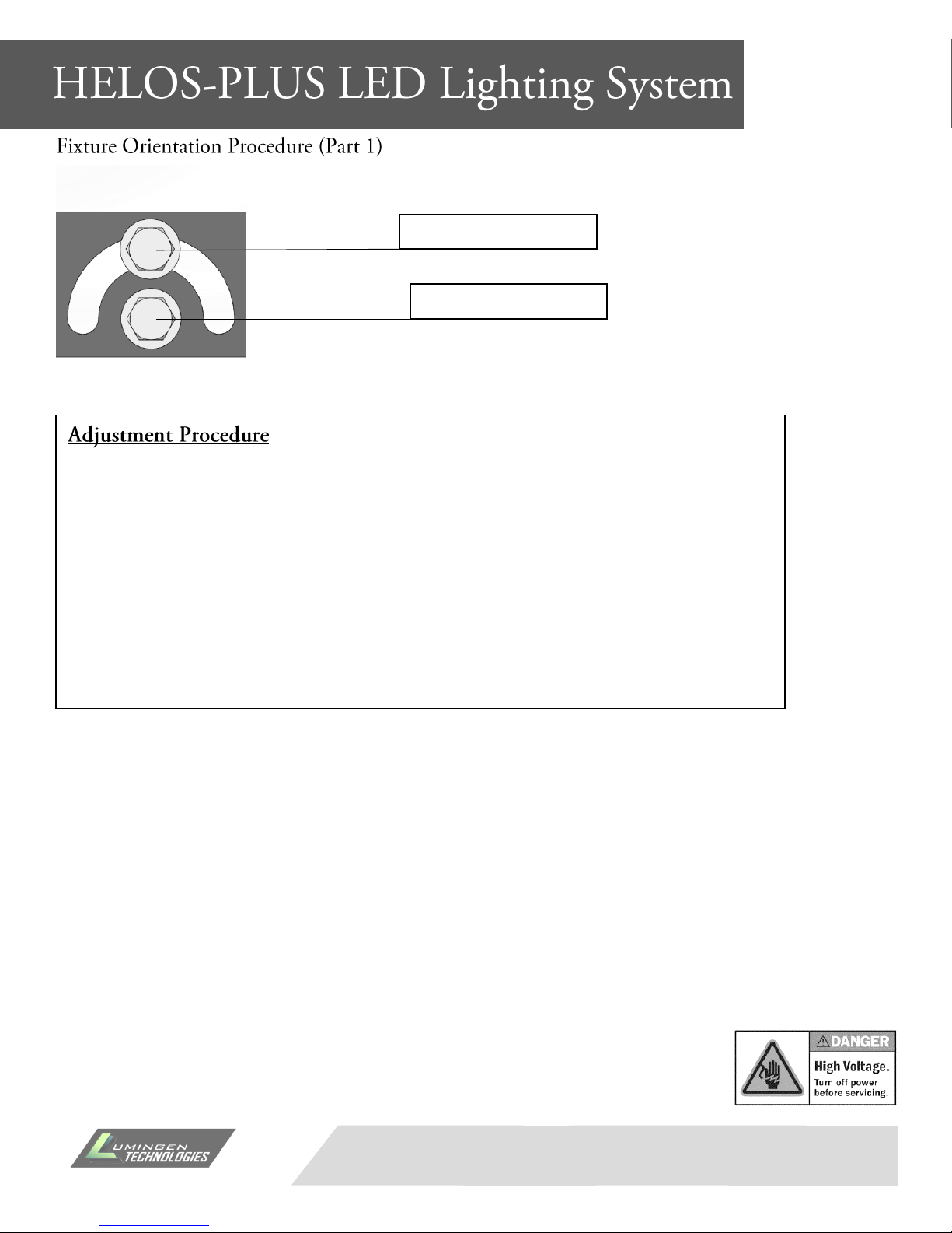
2. Loosen Acorn Nuts (do not remove the acorn nuts). Do
the same on the opposite end of the bracket. Caution:
support the light fixture to prevent unintended
movement of the fixture.
3. Adjust the orientation of the luminaire. Use appropriate
equipment to ensure the proper angular/linear
positions are met.
4. Tighten all Acorn Nuts. Do the same on the opposite
end of the bracket.
5. After the fixture returns to a secured state. Remove
supports and safety cables from the fixture.
Acorn Nut
Figure 8—the acorn nuts secure the bracket in any rotational
position (as permitted by the light fixture)

Data subject to change without notice.
Accessed Date: March 20, 2017
Visit us at www.lumingen.com or Call us at 1.604.371.4112
Lumingen Technologies, Ltd.
Electrical Installation
Page 10
Figure 10—
color code from left to right:
Black: AC/Line (AC100-480V)
Green: Ground
White: AC/Neutral
Figure 9—the depiction above references the color coding for all HELOS-
PLUS (SLD-XM-xxxx) Series luminaires.
Verify electrical codes with your electrical contractor. Input voltages:
AC100-480V compatibility.

Data subject to change without notice.
Accessed Date: March 20, 2017
Visit us at www.lumingen.com or Call us at 1.604.371.4112
Lumingen Technologies, Ltd.
Electrical Installation
Page 11
Table of contents
Popular Floodlight manuals by other brands

uSave LED
uSave LED USFL WPL Series installation instructions

Night Watcher
Night Watcher NW520 user guide

Mark
Mark LX 50G PRO user manual

Claypaky
Claypaky Odeon Flood Mini installation instructions

Timeguard
Timeguard MLW3000 Installation & operating instructions

NovaFlex
NovaFlex coloronix C-SS2-RGBW-120R manual