EcoSystem®Energi Savr NodeTM Installation Guide Lutron®|7
EcoSystem®Energi Savr NodeTM |Installation Guide
Step 6: QS link wiring
WARNING! Danger of Shock. May result in serious
injury or death.DONOTWIREWHENLIVE!Switchoff
power to all power feeds via circuit breaker or isolator
before wiring or servicing the EcoSystem Energi Savr
Node unit.
Buttons and LEDs in the unit are used for troubleshooting.
If wiring is exposed when accessing buttons and LEDs, the
unit must be accessed by a certied electrician, following
local codes.
QS link communication uses NEC®Class 2/PELV wiring. Follow
all local and national electrical codes when installing
NEC Class 2/PELV wiring with line voltage wiring.
The total length of the QS link wiring must not exceed 2000 ft
(610 m).
QS Link Wiring
Length Wire Gauge Available from
Lutron in one cable:
Less than
500 ft (153 m)
Power (terminals 1 and 2):
1 pair 18 AWG (1.0 mm2)
GRX-CBL-346S
Data (terminals 3 and 4):
1 pair 22 AWG (0.5 mm2),
twisted and shielded*
500 ft (153 m) to
2000 ft (610 m)
Power (terminals 1 and 2):
1 pair 12 AWG (4.0 mm2)
GRX-CBL-46L
Data (terminals 3 and 4):
1 pair 22 AWG (0.5 mm2),
twisted and shielded*
* Alternate Data-only cable: Use approved data link cable
(22 AWG (0.5 mm2) twisted/shielded) from Belden, model
#9461.
Check for compatibility in your area.
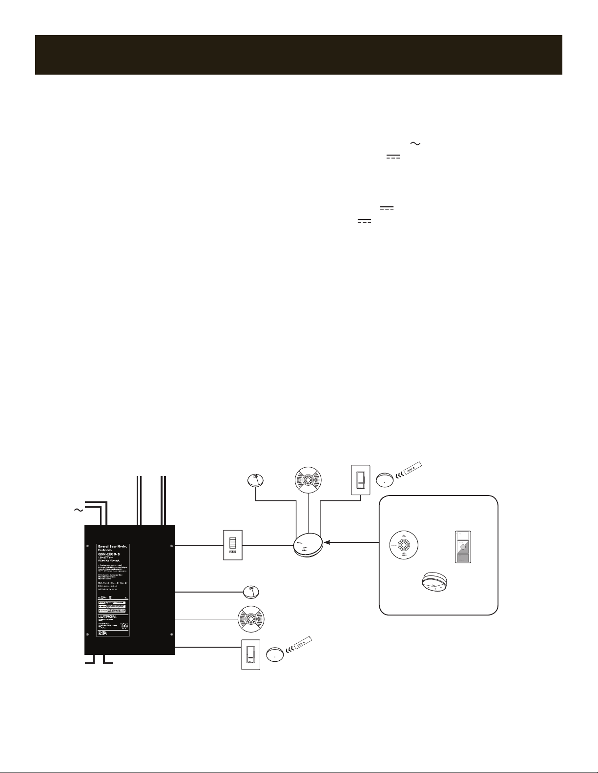
A QS system can have up to 100 zones, 100 areas, and 100 QS
devices. The EcoSystem Energi Savr Node unit counts as 1 QS
device and 1-100 zones.
See diagram on the right for QS link wiring.
1.Connect terminals 1, 3 and 4 to all EcoSystem Energi Savr Node
units.
2.Each EcoSystem Energi Savr Node unit has its own built-in
power supply.
3.Terminate the terminal 2 connection (24 V ) so that each
EcoSystem Energi Savr Node unit supplies power up to 30
Power Draw Units (PDUs). Each QS device should receive power
from only one EcoSystem Energi Savr Node unit.
NOTE: To connect extra QS devices, use a separate power
supply (24 V ), and only connect COM, MUX, and MUX to the
devices connected to the EcoSystem Energi Savr Node unit.
4.Wiring may be daisy chained or t-tapped.
Power draw calculations are not needed for wireless inputs or
inputs connected directly to the EcoSystem Energi Savr Node
units or EcoSystem ballasts.
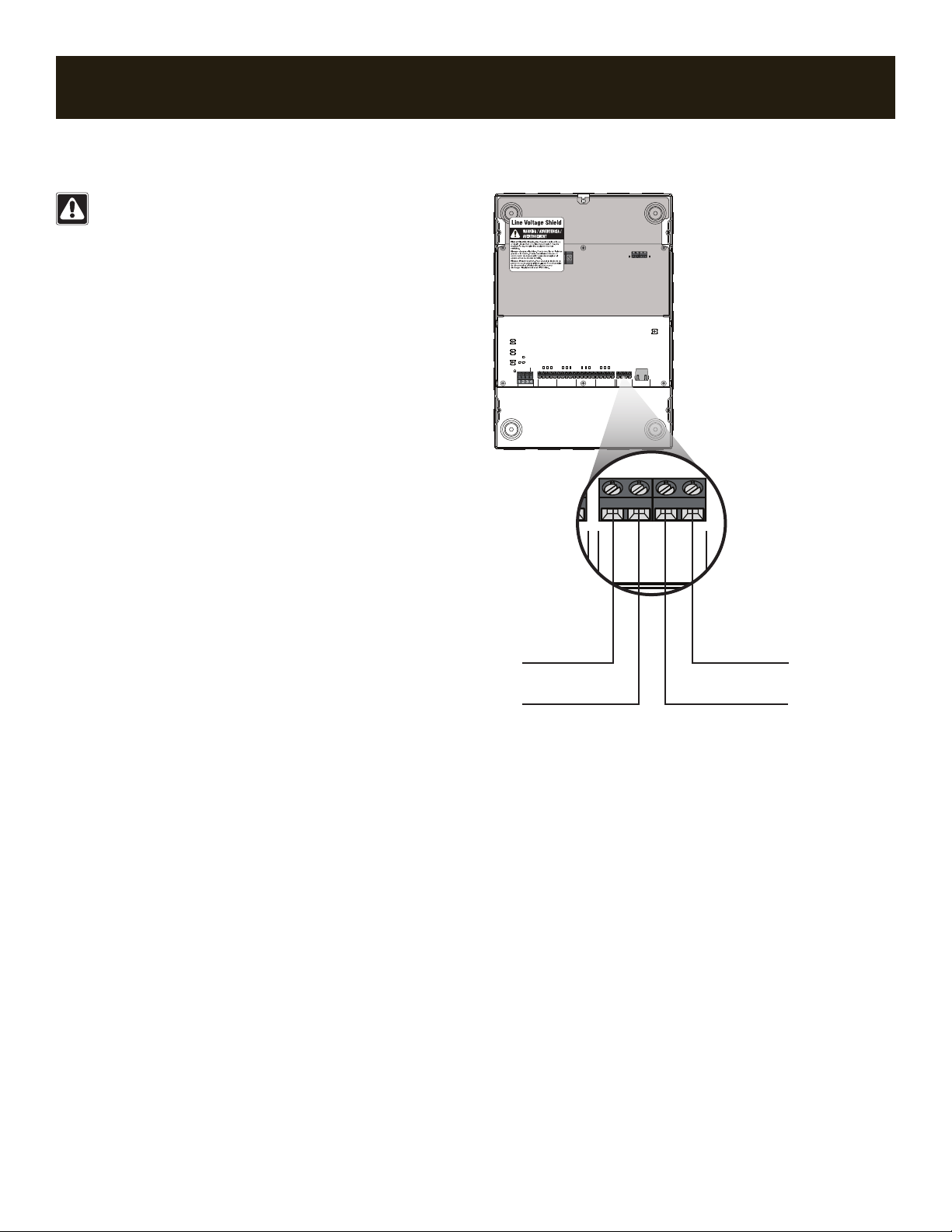
(4) MUX
(3) MUX
(2) 24 V
(1) COM
QS LINK
ECO1
ECO1
RESET
ECO2
TEST
GROUP 1
+20V
OCC 1
PHOTO 1
IR 1
COM
+24V
MUX
PWR
TEMPTEST
MUX
COM
GROUP 2
+20V
OCC 2
PHOTO 2
IR 2
COM
GROUP 3
+20V
OCC 3
PHOTO 3
IR 3
COM
GROUP 4
+20V
OCC 4
PHOTO 4
IR 4
COM
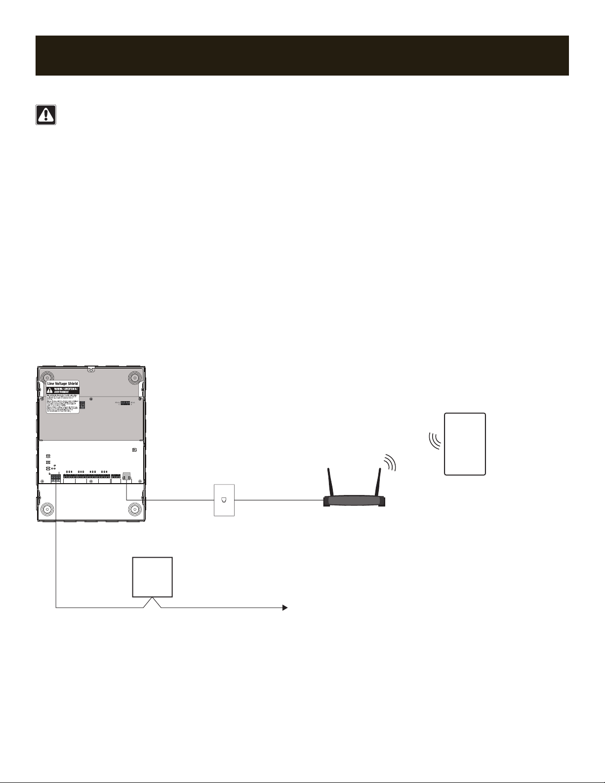
CONTACTCLOSURE ETHERNET
CCI
COM
EMERG
COM
ECO1
HNG
E
QS LINK
ECO1
ECO1
RESET
ECO2
TEST
GROUP 1
+20V
OCC 1
PHOTO 1
IR 1
COM
+24V
MUX
PWR
TEMPTEST
MUX
COM
GROUP 2
+20V
OCC 2
PHOTO 2
IR 2
COM
GROUP 3
+20V
OCC 3
PHOTO 3
IR 3
COM
GROUP 4
+20V
OCC 4
PHOTO 4
IR 4
COM
CONTACT CLOSURE ETHERNET
CCI
COM
EMERG
COM
ECO1
H N G
E
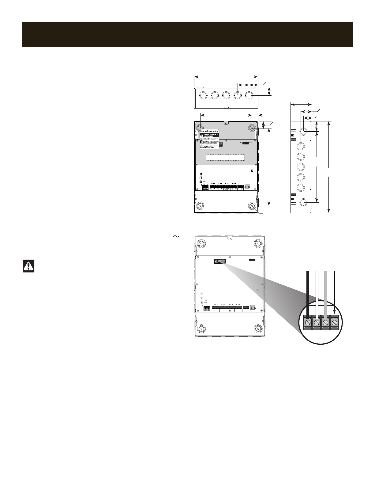
QS Link Wiring:
•22AWGto12AWG
(0.5 mm2to 4.0 mm2)
•Striplength:3/8in(8.5mm)
•Torque:5in-lbs(0.5N•m)
12 AWG (4.0 mm2)
18 AWG
(1.0 mm2)
QS Link Wiring
QS Link Terminal Connections
Each QS link terminal can accept only two 18 AWG (1.0 mm2)
wires. Two 12 AWG (4.0 mm2) conductors will not t. Connect as
shown below using appropriate wire connectors.