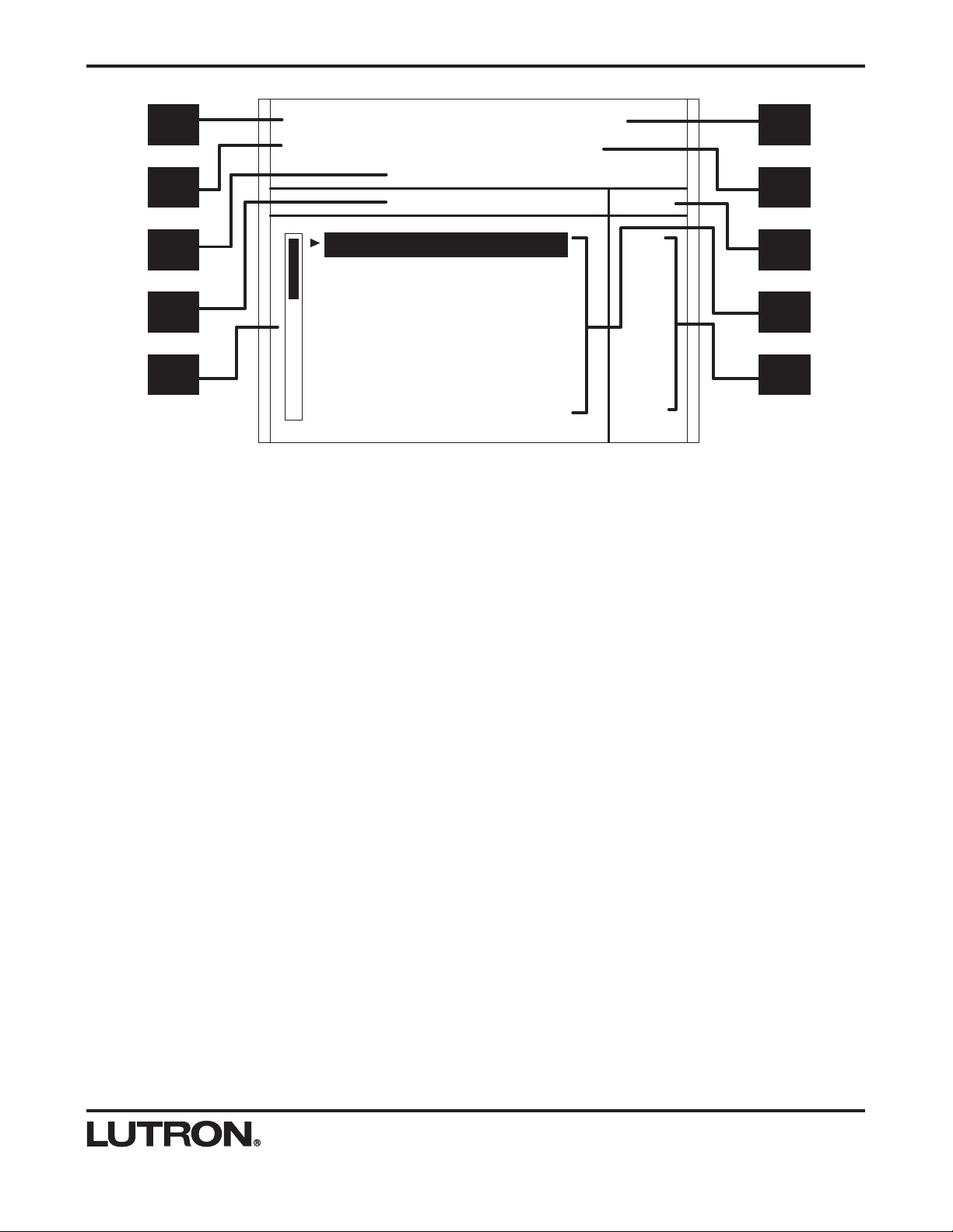
Lutron Electronics HOMEWORKS interactive HWI-HHP-LD User manual

TM
HWI-HHP-LD
Hand-Held Programmer
User’s Guide
V
8
G1
V1
G3
V
3
G4
V4
G9
G
1
2
V12
J3
J4
J5
12
3
4
8
12
3
4
4
12
3
4
8
12
3
4
12
3
4
Processor Assembly
WARNING
TURN OFF ALL CIRCUIT BREAKERS CONNECTEDTO P
ANEL
BEFORE SERVICING
Asegure en posición de apagado (OFF) cada uno de los
cortacircuitos de alimentación antes de darle servicio.
Panel Input:120VAC/2A 50/60 Hz
Bus Input/Output: Class 2 LowVoltage
ELECTRONICS CO., INC.
COOPERSBURG, PA 18036
(800) 523-9466
LUTRON
Comm. Link 3
RS-232 Link
Comm. Link 2
Processor Link
C +15 MUX MUX
Comm. Link 1
MI Link
C +15 MUX MUX
C
omm. Link
4
Pro
g
ramma
b
l
e
C
+1
5
M
U
X M
UX
Comm. Link 5
Programmable
C +15 MUX MUX
Comm. Link 6
Programmable
C +15 MUX MUX
Power Supply
Do Not Remove
Config.
Switch S1
Dia
g
nosti
c
Dis
p
l
a
y
Link 1
TX RX
Link 2
TX RX
Link 3
TX RX
Link 4
TX RX
Link 5
TX RX
Link
6
TX RX
Power Shorted on
Link 1,2,4,5, or 6 System Power
On
ESD Sensitive
Equipment
5
00
-
8
7
64
Æ
LI
S
TED 24
3C
IND
US
TRIA
L
CONTROL
L
EN
C
L
OSU
R
E
Config.
Switch S2
Link 7
+
LUTR
ON
LI
G
HTIN
G
S
Y
S
TE
M
HANDHEL
D
P
R
O
GRAMM
E
R
POR
T
BACK SELECT
RAISE
LOWER
UNDO
HELP
LEVEL
FADE
DELAY LAST
SCENE NEXT
SCENE
BUTTON
FINDER
FLASH MULTI


Table Of Contents
Instructions for Setup and Use
Introduction
Dimensions
System Preparation
System Preparation
How to Place a Programming Jack on the Floorplan
How to Upload and Lock Database
Using the Hand-Held Programmer
Connecting to the HomeWorks Interactive System
Important Notes
Care and Cleaning
Getting Started
Button Finder Navigation
Manual Navigation
Scene Programming
Button Layout
Screen Layout
Navigation
Home Screen
Area Screen
Room Screen
Keypad Screen
Button Screen
Scene Screen
Zone Screen
Zone Options
Level Change
Fade Change
Delay Change
Special Functions
Button Finder
Zone Flash
Last Scene
Next Scene
Multiple Zone Selection
Undo
Help
Specifications
Model Numbers
Hand-Held Programmer Specifications
Wiring and Connections
2
2
3
3
3
4
4
4
5
5
5
6
7
8
8
8
9
9
9
10
10
10
11
11
12
12
12
13
13
13
13
14
14
15

Instructions For Setup and Use
BACK SELECT
RAISE
LOWER
UNDO
HELP
LEVEL
FADE
DELAY LAST
SCENE NEXT
SCENE
BUTTON
FINDER
FLASH MULTI
HWI-HHP-LD
The Hand-Held Programmer (HHP) is an intuitive LCD
based device that provides rapid access to lighting
scenes in the HomeWorks Interactive System. It allows
the user to make real-time modifications to a scene's
light levels, fade times and delay times from within the
space and environment.
The Hand-Held Programmer connects to the system
through Programming Jacks placed discreetly throughout
the home or building to allow convenient adjustment of
the lighting settings from within the space.
Specifically, the user can:
• Activate and change (reprogram) the light level, fade,
and delay times of lighting zones within scenes in the
system.
• Select single, multiple, or all zones within a scene.
• Locate a selected zone or set of zones by flashing
them.
• Undo the last light level change.
• Quickly toggle between two scenes (Last Scene).
• Quickly navigate to the next scene on a button or key-
pad (Next Scene).
• Auto-navigate to a scene on a keypad using the Button
Finder feature.
Introduction
Dimensions
FRONT VIEW
241 mm
(9 1/2")
171 mm
(6 23/32")
TOP VIEW
44 mm
(1 3/4")
241 mm
(9 1/2")
2
The Hand-Held Programmer uses the equivalent of 45
LEDs on the keypad link. Make certain that connect-
ing the Hand-Held Programmer will not exceed the
300 LED limit of the processor, or the 350 LED limit if
the link is powered by an HWI-PS power supply.

System Preparation
Before using the Hand-Held Programmer, the project
must be prepared for it’s use. This includes:
1. Placing one or more Programming Jacks or an HHP
on the Floorplan.
2. Uploading the project with the Lock Database option
checked.
Caution - To use the Hand-Held Programmer,
the HomeWorks InteractiveTM software must be
Version 4.11 or higher.
System Preparation
How to Place a Programming Jack on
the Floorplan
1. Open the HomeWorks InteractiveTM software in
Control Station Mode.
2. Right-click in the controls toolbox. In the option box
that opens, click on “HHP Accessories.”
3. Scroll to the bottom of the controls toolbox and click
on the HHPJ-Q1 icon for Programming Jacks and the
HWI-HHP-LD icon for the Hand-Held Programmer. Click
on the rooms in the Floorplan where the Jacks are to be
placed. Alternately, a Hand-Held Programmer may be
placed in any location by clicking on the HWI-HHP-LD
icon and clicking on any room in the Floorplan. There
must be at least one Programming Jack or Hand-Held
Programmer on the Floorplan to enable the Hand-Held
Programmer in the software.
How to Upload and Lock Database
1. Open up the Terminal window.
2. Click the UP arrow to open the Upload Project dialog
box.
3. Under Compile Type, click the option “Compile and
Upload.”
4. Under Upload Type, click the option that says
“Synchronized with Scene Saver\HHP Allowed (Lock
Database).” If this option doesn’t exist, a Hand-Held
Programmer or Programming Jack has not been placed
on the Floorplan.
5. Click on “OK” to begin the upload. When the upload
is complete, the database will be locked, and the Hand-
Held Programmer may be used.
3

Connecting to the HomeWorks
Interactive System
Only one Hand-Held Programmer may be connected
to the system at any time.
1. Plug the HWI-HHP-LD into the HomeWorks Interactive
system:
a. Plug the end of the cable with the metal connector
into the top receptacle on the Hand-Held
Programmer.
b. Plug the end of the cable with the plastic con-
nector into the Programming Jack nearest the
room to reprogram.
2. The Hand-Held Programmer will begin to download
the database from the system processor, if it is not
already updated. The screen will indicate the progress of
the download.
3. The “Getting Started” section on the next page
describes how to begin using the Hand-Held
Programmer.
LUTR
ON
LI
G
HTIN
G
S
Y
S
TE
M
HANDHELD
P
R
O
GRAMM
E
R
POR
T
Important:
Do not pull on the cable to remove the connector
from the Hand-Held Programmer or the
Programming Jack. Pulling on the cable can dam-
age the cable and the connector. Instead, pull
back the collar on the connector to remove. See
above illustration for location of collars.
Using the HHP
4
HWI-HHPJ
HWI-HHP-LD
Plastic Metal
50 FEET
Collar

5
Getting Started
pad. If they aren't engraved, the list of buttons will typi-
cally be named "Button 1", "Button 2" and so on.
Position the cursor at the desired button and press the
SELECT button.
If there is only one scene programmed on the selected
button, that scene will be activated and the list of lighting
zones in that scene will be displayed with there respec-
tive light levels. If there are multiple scenes that can be
activated from that button (for example, one scene when
the button is pressed and another scene when the button
is double-tapped), the list of scenes will be displayed. In
this case, position the cursor at the desired scene and
press the SELECT button.
At any time, the user can navigate back to other scenes,
buttons, keypads, rooms, and areas by pressing the
BACK button.
SCENE PROGRAMMING
While programming a scene, the Hand-Held Programmer
has absolute control of those lighting zones. Keypad but-
tons, timeclock events, etc., are not permitted to adjust
those zones.
Using the arrow buttons ( ), select the desired
zone(s) to change. Using the RAISE and LOWER but-
tons, change the light level of the zone(s), causing the
scene to be reprogrammed to the new setting. Use the
LEVEL/FADE/DELAY button to reprogram zone fade
time and zone delay time. All changes take effect imme-
diately.
To modify a scene using the Hand-Held Programmer,
the user must first select the scene they want to edit.
There are two methods for accomplishing this. Button
Finder is the simplest method. It allows the user to
press the keypad button to activate the scene they want
to edit and the HHP automatically selects that scene. A
manual method of navigation is also available.
BUTTON FINDER NAVIGATION (RECOMMENDED)
Button Finder allows a user to “auto-navigate” to a light-
ing scene on a particular button in the system.
1. Press the BUTTON FINDER button on the Hand-
Held Programmer.
2. Press the keypad button to activate the scene that
the user wishes to reprogram.
The Hand-Held Programmer will automatically navigate
to that button. The user can then begin to make their
scene changes.
MANUAL NAVIGATION
Although the easiest and recommended way to navigate
to a lighting scene is by using BUTTON FINDER, the
user can manually navigate to the scene using naviga-
tion buttons on the HHP.
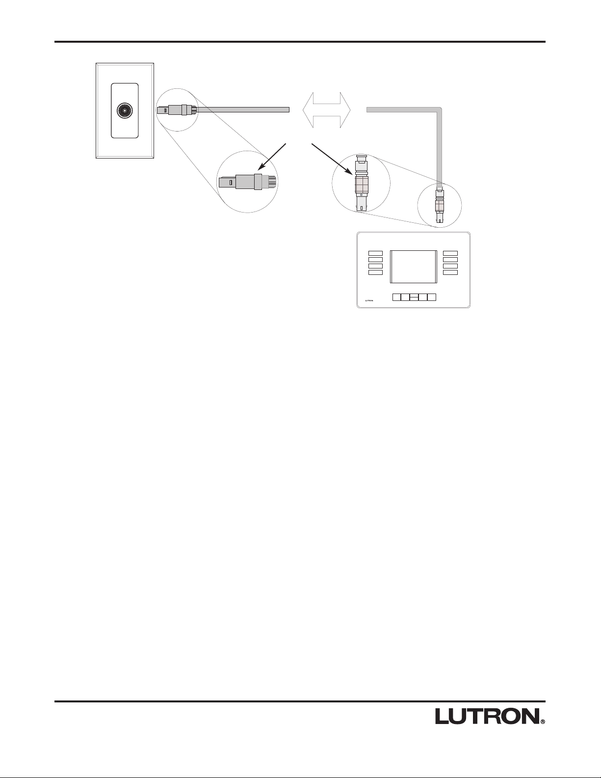
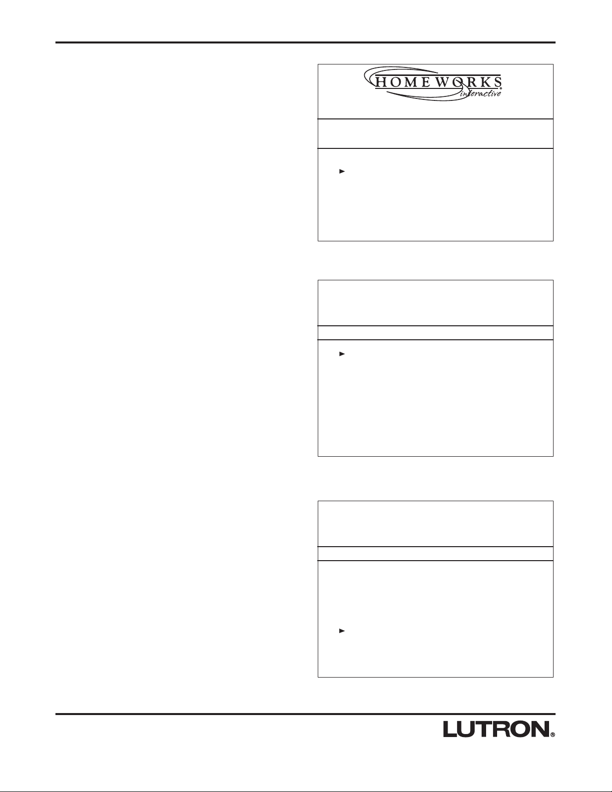
When plugged in, the Hand-Held Programmer starts on
the Home screen. Press the SELECT button to begin.
This will display a list of areas. Typically, a home is
divided into areas such as First Floor, Second Floor,
Exterior.
Using the UP/DOWN arrow buttons ( ), move the
cursor to the desired area to reprogram. When the cur-
sor is at the desired area, press the SELECT button.
This will display a list of rooms within that area, such as
Kitchen, Living Room, Foyer.
Position the cursor at the desired room and press the
SELECT button. This will display a list of keypads locat-
ed within the selected room. Keypads are typically
named according to location, style, number of buttons or
what they control.
Position the cursor at the desired keypad and press the
SELECT button. This will display a list of buttons on the
selected keypad. If the keypads are engraved, this list of
buttons should match the engraving on the actual key-
Getting Started

Button Layout
1. BACK - Backs up one navigation screen. Example:
Pressing the BACK button in the Keypad screen will take
the user back to the Room screen.
2. UP ARROW - Moves the cursor or selection up.
3. DOWN ARROW - Moves the cursor or selection down.
4. FLASH - Flashes (repeatedly turns on and off) the
selected zone(s) to help locate them.
5. SELECT - Selects the list item that the cursor is next
to.
6. RAISE - Increments the lighting level, fade time, or
delay time for the selected zone(s).
7. LOWER - Decrements the lighting level, fade time, or
delay time for the selected zone(s).
8. MULTI - The user may select multiple zones using the
MULTI button. Highlight the first zone to select and press
the MULTI button. Highlight the next zone to select and
press the MULTI button again. Repeat for each additional
zone. The user can select all zones in a scene by quick-
ly double-tapping the MULTI button. To deselect a zone,
position the cursor next to the zone and press the MULTI
button. Pressing the SELECT button will return to select-
ing one zone.
9. LEVEL/FADE/DELAY - Toggles between level, fade,
and delay in the Zones screen.
10. BUTTON FINDER - Allows the user to auto-navigate
to a scene. Press the BUTTON FINDER button on the
HHP. Press the keypad button to reprogram. The Hand-
Held Programmer will automatically navigate to the first
scene on that button.
11. UNDO - Enables the user to cancel the last level
change made to the selected zone(s) and revert back to
their previous levels.
12. HELP - Provides information to help the user operate
the Hand-Held Programmer.
13. LAST SCENE - Quickly toggles between two
scenes.
14. NEXT SCENE - Navigates to the next scene on a
button or keypad with a single button press.
BACK SELECT
RAISE
LOWER
UNDO
HELP
LEVEL
FADE
DELAY
LAST
SCENE NEXT
SCENE
BUTTON
FINDER
FLASH MULTI
1
13
121110
14
9
4
3
2
8
7
6
5
AREA:
KP:
ROOM:
BTN:
SELECT ZONE
Living Room Downlights
Living Room East Track
Living Room Fireplace Art
Living Room West Track
Theatre Aisle
Theatre Posters
Theatre Sconces
1st Floor Living Room
EntertainArchway
Default Toggle - Press On
LEVEL
45%
49%
70%
35%
60%
60%
38%
6

Screen Layout
A. AREA - Currently selected area. Examples: 1st Floor,
Basement, Landscape.
B. ROOM - Currently selected room. Examples: Living
Room, Media Room, Kitchen.
C. KP - Currently selected keypad. Examples: Archway,
Her Side, Top of Stairs.
D. BTN - Currently selected button. The name displayed
reflects the engraving entered in the software.
Examples: Entertain, Relax, All On.
E. Programming Model and Action Type - Denotes the
programming model and action for the selected button.
Example: A button that is set up as a default toggle will
display as “Default Toggle Press On”, where “Default
Toggle” is the programming model and “Press On” is the
action type.
F. SELECT “ ” - Displays the type of list item you are
currently affecting. Examples: SELECT ROOM,
SELECT BUTTON, SELECT ZONE.
G. LEVEL/FADE/DELAY - Indicates what values are
currently displayed (Level, Fade, or Delay values). This
will only display in the Zones screen.
H. Scroll Bar - If the current list contains more items
than the screen can display, the scroll bar will appear,
indicating that there are more items to display. As the
UP/DOWN arrow buttons are used to scroll through the
list, the position of the indicator in the scroll bar will
change to reflect the current position in the list. In the
above picture, the scroll bar indicates the position as the
top of the list with additional items to follow.
I. Context List - This list displays the items available for
selection.
J. Value List - This list displays the current values for
the items in the context list.
AREA:
KP:
ROOM:
BTN:
SELECT ZONE
Living Room Downlights
Living Room East Track
Living Room Fireplace Art
Living Room West Track
Theatre Aisle
Theatre Posters
Theatre Sconces
1st Floor Living Room
EntertainArchway
Default Toggle - Press On
LEVEL
45%
49%
70%
35%
60%
60%
38%
A
C
E
F
H
B
D
G
I
J
7

Navigation
AREA:
KP:
ROOM:
BTN:
SELECT AREA
1st Floor
2nd Floor
Landscape
AREA:
KP:
ROOM:
BTN:
SELECT ROOM
Dining Room
Foyer
Hallway
Kitchen
Living Room
Stairs
Theatre
1st Floor
Area Screen
This screen displays the area names in the system.
Use the arrow buttons to move the cursor to the desired
area name. Use the SELECT button to select the desired
area. The Hand-Held Programmer will now display the
Room screen, where the user will choose the room to
display.
Room Screen
This screen displays the room names in the area select-
ed in the previous screen.
Use the arrow buttons to move the cursor to the desired
room name. Use the SELECT button to select the
desired room. The Hand-Held Programmer will now dis-
play the Keypad screen, where the user will choose the
keypad to display.
8
Home Screen
This screen is the first screen that is displayed when the
Hand-Held Programmer is ready to use.
Press the SELECT button to move to the next screen.
Program Button Scenes
Use the Up and Down Arrows and the SELECT
button to Navigate to the Desired Scene.
COPYRIGHT, LUTRON ELECTRONICS, 2002

AREA:
KP:
ROOM:
BTN:
SELECT BUTTON
Showtime
Relax
Entertain
Cleanup
LR Off
1st Floor
Archway
Living Room
AREA:
KP:
ROOM:
BTN:
SELECT SCENE
Press On
Double Tap
1st Floor
Archway
Living Room
Entertain
Default Toggle
Button Screen
This screen displays the button names on the keypad
selected in the previous screen.
Use the arrow buttons to move the cursor to the desired
button name. Use the SELECT button to select the key-
pad button. The Hand-Held Programmer will now display
the Scene screen, where the user will choose the scene
to display. If there is only one scene on the button, the
HHP will display the Zone screen, where the user will
choose the zone(s) to change.
Scene Screen
This screen displays the scenes available on the button
selected in the previous screen.
Use the arrow buttons to move the cursor to the desired
scene name. Use the SELECT button to select the
scene. The Hand-Held Programmer will now display the
Zone screen, where the user will choose the zone(s) to
change.
If there is only one scene on the button, the Hand-Held
Programmer will not display this screen. Instead, it will
display the Zone screen, where the user will choose the
zone(s) to change.
Navigation
9
AREA: 1st Floor
KP:
ROOM: Living Room
BTN:
SELECT KEYPAD
Archway
Deck Entry
Library Entry
Keypad Screen
This screen displays the keypad names in the room
selected in the previous screen.
Use the arrow buttons to move the cursor to the desired
keypad name. Use the SELECT button to select the
desired keypad.

AREA:
KP:
ROOM:
BTN:
SELECT ZONE
Living Room Downlights
Living Room East Track
Living Room Fireplace Art
Living Room West Track
Theatre Aisle
Theatre Posters
Theatre Sconces
1st Floor Living Room
EntertainArchway
Default Toggle - Press On
LEVEL
45%
49%
70%
35%
60%
60%
38%
Zone Screen
This screen displays the lighting zone names on the but-
ton selected in the previous screen. The user can make
changes to level, fade time, and delay time for the
selected zone(s).
Use the arrow buttons to highlight the desired zone
name.
Zone Options
On the Zone screen, the user may toggle between light level, fade time, and delay time by pressing the
LEVEL/FADE/DELAY button. There are three parameters that can be changed for each zone selected:
Navigation
1. LEVEL
This is the zone output from 0% (OFF) to 100% (Full ON) for dimmed zones, OFF or ON for switched zones, or scene
number for GRAFIK Eye®scenes. The user can also FLASH the selected zone, allowing them to locate the zone in the
space they are working in. FLASH applies only to dimmed or switched zones.
2. FADE
This is the amount of time it will take for the zone to reach the scene level from the level it was at previously. This
applies only to dimmed zones.
3. DELAY
This is the amount of time that the zone will wait after the keypad button press before it begins its fade to the scene
level.
AREA:
KP:
ROOM:
BTN:
SELECT ZONE
Living Room Downlights
Living Room East Track
Living Room Fireplace Art
Living Room West Track
Theatre Aisle
Theatre Posters
Theatre Sconces
1st Floor Living Room
EntertainArchway
Default Toggle - Press On
LEVEL
45%
49%
70%
35%
60%
60%
38%
Level Change
Use the RAISE and LOWER buttons to ramp the values
up and down. Pressing and holding the RAISE or
LOWER buttons will speed up the rate at which the value
increments or decrements. Pressing and holding the
RAISE or LOWER buttons and then pressing the UP
arrow or DOWN arrow will quickly change the value in
large increments.
For dimmed zones, a single press of the RAISE or
LOWER button will result in a 1% change. For switched
zones, a press will change the value between ON and
OFF. For GRAFIK Eye®scenes, a press will increment or
decrement the value between the OFF Scene and Scene
16.
LEVEL
FADE
DELAY
10

AREA:
KP:
ROOM:
BTN:
SELECT ZONE
Living Room Downlights
Living Room East Track
Living Room Fireplace Art
Living Room West Track
Theatre Aisle
Theatre Posters
Theatre Sconces
1st Floor Living Room
EntertainArchway
Default Toggle - Press On
DELAY
00:02.00
00:00.00
00:00.00
00:00.00
00:00.00
00:00.00
00:00.00
Delay Change
Use the RAISE and LOWER buttons to ramp the values
up and down. Adjustments will be by 0.25 second incre-
ments up to 10 seconds, by 1 second increments up to
60 seconds, and by 1 minute increments above 60 sec-
onds. Pressing and holding the RAISE or LOWER but-
tons will speed up the rate at which the value increments
or decrements.
Navigation
11
AREA:
KP:
ROOM:
BTN:
SELECT ZONE
Living Room Downlights
Living Room East Track
Living Room Fireplace Art
Living Room West Track
Theatre Aisle
Theatre Posters
Theatre Sconces
1st Floor Living Room
EntertainArchway
Default Toggle - Press On
FADE
00:05.25
00:03.50
00:03.50
00:03.50
00:03.50
00:03.50
00:03.50
Fade Change
Use the RAISE and LOWER buttons to ramp the values
up and down. Adjustments will be by 0.25 second incre-
ments up to 10 seconds, by 1 second increments up to
60 seconds, and by 1 minute increments above 60 sec-
onds. Pressing and holding the RAISE or LOWER but-
tons will speed up the rate at which the value increments
or decrements.
This applies only to dimmed zones.

Special Functions
AREA:
KP:
ROOM:
BTN:
SELECT ZONE
Living Room Downlights
Living Room East Track
Living Room Fireplace Art
Living Room West Track
Theatre Aisle
Theatre Posters
Theatre Sconces
1st Floor Living Room
EntertainArchway
Default Toggle - Press On
LEVEL
45%
49%
70%
35%
60%
60%
38%
AREA:
KP:
ROOM:
BTN:
SELECT ZONE
Dining Room Art
Dining Room Chandelier
Dining Room Downlights
Dining Room Sconces
Dining Room Side Table
Dining Room Wallwashers
1st Floor Dining Room
EntertainLR Entry
Default Toggle - Press On
LEVEL
36%
40%
15%
28%
25%
53%
Last Scene
The LAST SCENE button enables the user to toggle
between the last scene they edited and the one they are
currently editing. Pressing the LAST SCENE button navi-
gates to the last scene they edited. Pressing the button
again navigates back to the scene the user was editing
before they pressed the button.
12
AREA:
KP:
ROOM:
BTN:
SELECT ZONE
Living Room Downlights
Living Room East Track
Living Room Fireplace Art
Living Room West Track
Theatre Aisle
Theatre Posters
Theatre Sconces
1st Floor Living Room
EntertainArchway
Default Toggle - Press On
LEVEL
FLASH
49%
70%
35%
60%
60%
38%
Zone Flash
The Hand-Held Programmer can flash a lighting zone to
allow the user to find its location.
Press the FLASH button to enter flash mode for the
selected zone. The level value will display FLASH. To
exit flash mode, press the FLASH button again. The level
will return to its previous setting.
This applies only to dimmed or switched zones.
AREA:
KP:
ROOM:
BTN:
SELECT ZONE
Liv Rm Downlights
Liv Rm East Track
Liv Rm Fireplace Art
Living Room West Track
Theatre Aisle
Theatre Posters
Theatre Sconces
1st Floor Living Room
EntertainArchway
Default Toggle - Press On
FADE
00:05.25
00:03.50
00:03.50
00:03.50
00:03.50
00:03.50
00:03.50
Press Keypad Button to Display the
Scene Activated by that Button.
Press any Button to Cancel
Button Finder
The Hand-Held Programmer can automatically navigate
to a button on a keypad. Press the BUTTON FINDER
button on the Hand-Held Programmer and then press the
desired button on the keypad to be reprogrammed.
This function is available from any screen.

13
Help
Pressing the HELP button will display a screen providing information to help the user operate the Hand-Held
Programmer.
Undo
The UNDO button enables the user to cancel the last level changes made to the selected zone(s) and revert back to
their previous levels.
This button works with LEVEL (not FADE or DELAY).
AREA:
KP:
ROOM:
BTN:
SELECT ZONE
Living Room Downlights
Living Room East Track
Living Room Fireplace Art
Living Room West Track
Theatre Aisle
Theatre Posters
Theatre Sconces
1st Floor Living Room
EntertainArchway
Default Toggle - Press On
LEVEL
46%
49%
70%
36%
61%
60%
38%
Multiple Zone Selection
The user may select multiple zones using the MULTI but-
ton. Highlight the first zone to select and press the
MULTI button. Highlight the next zone to select and
press the MULTI button again. Repeat for each addition-
al zone to select. The user can select all zones in a
scene by quickly double-tapping the MULTI button. All of
the selected zones will raise and lower together propor-
tionally. To deselect a zone, position the cursor next to
the zone and press the MULTI button. Pressing the
SELECT button will return to selecting one zone.
The user cannot multi-select both dimmed and switched
zones at the same time, nor can they multi-select
GRAFIK Eye®scenes.
AREA:
KP:
ROOM:
BTN:
SELECT ZONE
Living Room Downlights
Living Room East Track
Living Room Fireplace Art
Living Room West Track
Theatre Aisle
Theatre Posters
Theatre Sconces
1st Floor Living Room
EntertainArchway
Default Toggle - Press On
LEVEL
45%
49%
70%
35%
60%
60%
38%
AREA:
KP:
ROOM:
BTN:
SELECT ZONE
Living Room Downlights
Living Room East Track
Living Room Fireplace Spots
Living Room West Track
1st Floor
Cleanup
Default Toggle - Press On
LEVEL
100%
100%
100%
100%
Living Room
Archway
Next Scene
The NEXT SCENE button enables the user to move to
the next scene on the current keypad. If the current
scene is the last scene on the keypad, pressing NEXT
SCENE will move to the first scene of the next keypad in
the current room.
Special Functions

Specifications
The Hand-Held Programmer requires the HomeWorks InteractiveTM Programming Utility ver-
sion 4.11 or higher.
The Hand-Held Programmer is equipped with a 50 foot (15.24m) cord. This will help deter-
mine the locations and spacing of the Programming Jacks (HWI-HHPJ). For extended
reach, a single 50 foot (15.24m) extension is available as P/N HWI-HHP-EXTCORD. The
Programming Jack locations that require the use of a 50 foot (15.24m) extension must be
wired as a single homerun to the processor with no additional keypads on that homerun.
For estimating processor/power supply requirements, the Hand-Held Programmer is equiva-
lent to three HWI-KP-15 keypads or 45 LEDs. This power supply requirement applies to
every HomeWorks InteractiveTM processor that may have a Hand-Held Programmer attached
to it. The HomeWorks InteractiveTM Programming Utility will help determine the power supply
requirements.
To avoid damage to the Hand-Held Programmer and to maximize the life of the battery and
the display, do not expose the unit to extreme heat or cold. Ambient storage temperature:
32-104°F (0-40°C). Ambient storage humidity: 0-90% humidity, non-condensing.
To maintain acceptable screen performance, operation of the Hand-Held Programmer in
temperatures between 50-95°F (10-35°C) is recommended.
Use only a damp cloth with a mild soap solution to clean the Hand-Held Programmer. Do
not use any chemical or abrasive cleaners.
The Hand-Held Programmer is designed to have a minimum life of 5 years in the most
extreme environmental conditions. The expected life for a unit that is stored and used at nor-
mal room temperatures exceeds 10 years.
Cord
Power Consumption
Storage
Service Life
HWI-HHP-LD
HWI-HHP-REPLCORD
HWI-HHP-EXTCORD
HWI-HHPJ-Q1
HWI-HHPJ-Q4
Hand-Held Programmer (matte silver finish)
Replacement cable for use with Hand-Held Programmer - 50 feet (15.24m).
Extension cable - 50 feet (15.24m). Extendes total cable reach to 100 feet (30.48m). See
Cord Specification below.
Hand-Held Programmer Programming Jack - Quantity 1
Hand-Held Programmer Programming Jack - Quantity 4
Programming Jack Colors: White, Black, Beige, Ivory, Gray, Brown, Taupe
Model Number Description
Hand-Held Programmer Specifications
14
Operating Conditions
Care and Cleaning
HomeWorks
Interactive Software

The Programming Jacks (HWI-HHPJ) connect to a Keypad Link on the
HomeWorks InteractiveTM processor. The Hand-Held Programmer connects to
the Programming Jacks distributed throughout the residence.
The Hand-Held Programmer does not get addressed nor does it take up any
addresses on the Keypad Link. Up to 32 keypads can still be connected to
the link as long as wire length and power supply limitations are not exceeded.
Programming Jacks (HWI-HHPJ) may be wired in any configuration (star,
daisy-chain, etc.), similarly to how keypads are wired. There is no limitation to
the number of Programming Jacks on a link. However, since up to 10 key-
pads may occupy a single homerun, any homerun that has one or more
Programming Jacks on it must consider the Hand-Held Programmer as 3 of
the 10 keypads.
Only one Hand-Held Programmer may be connected to the system at any
time.
Since the Programming Jacks are attached to the keypad link, the same wire
type is used. The specification for this wire is two pair[one pair #18AWG
(1.0mm2), one pair #18-22AWG (0.5-1.0mm2) twisted shielded]. Lutron wire,
model #GRX-CBL-346S-500 may be used.
The Programming Jack is connected to the HomeWorks InteractiveTM Keypad
Link using a four-pin removable terminal block. Each pin will accept up to one
#18AWG (1.0mm2) wire. The Programming Jack is installed in a single-gang
wallbox.
Wiring and Connections
Connection to
HomeWorks
InteractiveTM System
Addressing
Wiring for
Programming Jacks
Number of HWI-HHP-LD Per System
Wire Type for Programming Jacks
Programming Jack Installation
Wiring and Connections
15

Notes
16

Notes
17

World Headquarters
Lutron Electronics Co., Inc.
7200 Suter Road
Coopersburg, PA 18036-1299, U.S.A.
TOLL FREE: (800) 523-9466 (U.S.A., Canada and the Caribbean)
Tel: (610) 282-3800; International 1 610 282-3800
Fax: (610) 282-3090; International 1 610 282-3090
LIMITED WARRANTY
Lutron will, at its option, repair or replace any unit that is defective in materials or manufac-
ture within two years after purchase. For warranty service, return unit to place of purchase or
mail to Lutron at 7200 Suter Rd., Coopersburg, PA 18036-1299, postage pre-paid.
Telephone the Lutron Technical Support Center toll free at 800-523-9466. After the two year
period, a pro-rated warranty applies to this product until eight years after the purchase. For
more information regarding this warranty contact your Lutron representative.
THIS WARRANTY IS IN LIEU OF ALL OTHER EXPRESS WARRANTIES, AND THE
IMPLIED WARRANTY OF MERCHANTABILITY IS LIMITED TO TWO YEARS FROM PUR-
CHASE. THIS WARRANTY DOES NOT COVER THE COST OF INSTALLATION,
REMOVAL OR REINSTALLATION, OR DAMAGE RESULTING FROM MISUSE, ABUSE,
OR IMPROPER OR INCORRECT REPAIR, OR DAMAGE FROM IMPROPER WIRING OR
INSTALLATION. THIS WARRANTY DOES NOT COVER INCIDENTAL OR CONSEQUEN-
TIAL DAMAGES. LUTRON’S LIABILITY ON ANY CLAIM FOR DAMAGES ARISING OUT
OF OR IN CONNECTION WITH THE MANUFACTURE, SALE, INSTALLATION, DELIV-
ERY, OR USE OF THE UNIT SHALL NEVER EXCEED THE PURCHASE PRICE OF THE
UNIT.
This warranty gives you specific legal rights, and you may also have other rights which vary
from state to state. Some states do not allow limitations on how long an implied warranty
lasts, so the above limitation may not apply to you. Some states do not allow the exclusion
or limitation of incidental or consequential damages, so the above limitation or exclusion may
not apply to you.
Technical and Sales Assistance
If you need assistance, call the toll-free Lutron
Technical Support Center. Please provide exact
model number when calling.
(800) 523-9466 (U.S.A., Canada and the Caribbean)
Other countries call:
Tel: (610) 282-3800
Fax: (610) 282-3090
Visit our Web site at www.lutron.com
Lutron Electronics Co., Inc.
7200 Suter Road
Coopersburg, PA 18036-1299
Made and printed in the U.S.A. P/N 043-096 Rev. A 5/02
This product may be covered under one or more of the following U.S. patents: 4,797,599;
4,889,999; 5,170,068; 5,237,207; D421,399; D431,199 and corresponding foreign patents.
U.S. and foreign patents pending. Lutron, GRAFIK Eye, and HomeWorks are registered
trademarks. HomeWorks Interactive and the HomeWorks Interactive logo are trademarks of
Lutron Electronics Co., Inc.
© 2002 Lutron Electronics Co., Inc.
Table of contents
Other Lutron Electronics Motherboard manuals