Table of Contents
_____________________________________________________________________________________________
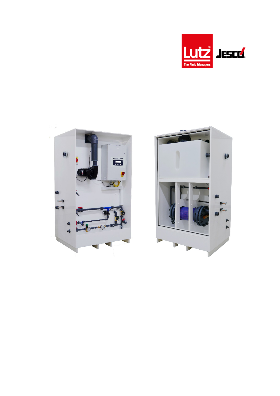
3 | Installation, Operation & Maintenance Instructions EASYCHLORGEN
Contents
1. NOTES FOR THE READER..................................................4
1.1 INTRODUCTION ...................................................................4
1.2 EXPLANATION OF THE SIGNAL WORDS....................................4
1.3 EXPLANATION OF THE WARNING SIGNS...................................4
1.4 IDENTIFICATION OF WARNINGS..............................................4
1.5 INSTRUCTION FOR ACTION IDENTIFICATION .............................4
1.6 REFERENCES TO INTELLECTUAL PROPERTY RIGHTS.................4
1.7 DETAILS FOR THE OPERATOR ...............................................4
1.8 INSTRUCTION &TRAINING COURSE ASSISTANCE......................5
1.9 EXAMPLE OF TRAINING COURSE TOPICS.................................5
2. SAFETY................................................................................7
2.1 GENERAL WARNINGS...........................................................7
2.2 HAZARDS DUE TO NON-COMPLIANCE WITH THE SAFETY
INSTRUCTIONS .........................................................................7
2.3 WORKING IN A SAFETY-CONSCIOUS MANNER ..........................7
2.4 PERSONAL PROTECTIVE EQUIPMENT......................................7
2.5 PERSONNEL QUALIfiCATION..................................................7
3. INTENDED USE....................................................................9
3.1 NOTES ON PRODUCT WARRANTY...........................................9
3.2 INTENDED PURPOSE............................................................9
3.3 DEVICE REVISION ...............................................................9
3.4 SODIUM CHLORIDE CHEMICAL SPECIFICATION .........................9
3.5 WATER QUALITY.................................................................9
3.6 STANDARD WARRANTY CONDITIONS ......................................9
4. PRODUCT DESCRIPTION..................................................10
4.1 SCOPE OF DELIVERY .........................................................10
4.2 DESIGN AND FUNCTION......................................................10
5. TECHNICAL DATA..............................................................15
5.1 EASYCHLORGEN SKID UNIT ...........................................15
5.2 POWER SUPPLY UNIT.........................................................15
6. DIMENSIONS .....................................................................16
6.2 INTERMEDIATE BRINE TANK ................................................17
6.3 POWER SUPPLY UNIT (PSU) CABINET .................................17
7. INSTALLATION...................................................................18
7.1 INSTALLATION LOCATION....................................................18
7.2 HYDRAULIC INSTALLATION..................................................19
7.3 ELECTRICAL INSTALLATION ...............................................22
7.4 GENERAL INSTALLATION LAYOUTS.......................................31
8. CONTROL ..........................................................................35
8.1 CONTROL DISPLAY ............................................................35
9. START UP...........................................................................36
9.1 COMMISSIONING AND INITIAL START-UP...............................36
9.2 NORMAL START-UP..........................................................39
10. OPERATION.....................................................................40
10.1 AUTOMATIC OPERATION ..................................................40
10.2 MANUAL INHIBIT..............................................................40
10.3 REMOTE INHIBIT .............................................................40
10.4 SOFTENER REGENERATION..............................................40
10.5 EMERGENCY SHUTDOWN.................................................41
10.6 RECORD LOG OF OPERATION...........................................41
11. SHUTDOWN.....................................................................42
11.1 SHORT-TERM SHUTDOWN (UP TO 6MONTHS)......................42
11.2 LONG-TERM SHUTDOWN ..................................................42
11.3 STORAGE ......................................................................42
11.4 TRANSPORTATION ..........................................................42
11.5 DISPOSAL OF OLD EQUIPMENT..........................................42
12. MAINTENANCE................................................................43
12.1 MAINTENANCE INTERVALS ...............................................43
12.2 ELECTROLYSER CLEANING ...............................................46
12.3 FINISHING MAINTENANCE .................................................47
12.4 LOCATION OF MAINTENANCE PARTS...................................48
13. TROUBLE-SHOOTING .....................................................50
14. SPARE PARTS...........................................................51
14.1 MAINTENANCE SETS...................................................51
14.2 CRITICAL SITE SPARES ....................................................51
15. DECLARATION OF NO OBJECTION..........................52
16. WARRANTY CLAIM ...................................................53
APPENDIX I – COMMISSIONING LOG....................................54
COMMISSIONING /SERVICE SHEET TO BE COMPLETED AND KEPT ON
SITE.....................................................................................54
APPENDIX II – OPERATORS LOG..........................................55
OPERATORS LOG TO BE COMPLETED AND KEPT ON SITE............55
APPENDIX III – SERVICE LOG ...............................................56
SERVICE CHECK SHEET..........................................................56
APPENDIX IV – SOFTENING EQUIPMENT.............................57
INDEX .....................................................................................75