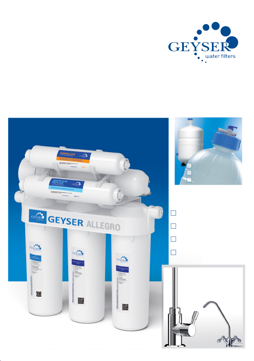
Geyser ALLEGRO User manual

GEYSER
ALLEGRO
WATER PURIFICATION SYSTEM ON
THE BASIS OF THE REVERSE OSMOSIS
MANUAL
for installation and operation of a
HOUSEHOLD FILTER
MODIFICATIONS
GEYSER-ALLEGRO
GEYSER-ALLEGRO P
GEYSER-ALLEGRO PM
GEYSER-ALLEGRO M
8 l
12 l
16 l

2
TABLE OF CONTENTS:
Geyser technologies ...................................................................................... 3
Purpose ......................................................................................................... 3
Technical characteristics............................................................................... 3
Requirements to the source water ................................................................. 4
Connection diagrams and a scope of delivery of............................................ 5
Geyser-Allegro............................................................................................... 5
Geyser-Allegro M ........................................................................................... 6
Geyser-Allegro P............................................................................................ 7
Geyser-Allegro PM......................................................................................... 8
Electrical scheme .......................................................................................... 9
System installation........................................................................................ 9
System flush ................................................................................................11
System maintenance ....................................................................................12
List of possible failures and methods of their elimination ............................13
Warranty liabilities........................................................................................15
Thank you for choosing this water lter «Geyser»!
Our developments and technologies allow providing with the water perfect quality
in your house.
All functionality capabilities, an also a method of installation of the water
purication system Geyser are described in this manual. Please read it carefully and
retain for future reference.
The water purier set includes all parts required for using immediately after the
installation.

3
GEYSER TECHNOLOGIES
Safety – removal of all impurities. Absolutely clean water.
Efciency – the modern high-performing membrane, with a size of pores of 0.0001µm.
Cost effectiveness – the effective preliminary purication system prolonging the membrane’s
service life.
Ecological compatibility – all elements of the system are certied for contact with food
products.
Mineralization – the useful water with an optimal mineral composition due to the mineralizer
(patent No. 2212378).
PURPOSE
Geyser-Allegro lter is used for the deep purication of the tap water by the reversed
osmosis from mechanical admixtures, chloride and organic compounds, carbolic acids,
bacteria and viruses. The system decreases the water hardness, removes a foreign flavour,
smell and color.
TECHNICAL CHARACTERISTICS
The storage tank volume (water volume in the storage tank is up to 70%*of its
volume), l 8; 12; 16
Excessive air pressure in the storage tank, atm. 0.4-0.5
Performance (depends on the water pressure and temperature, see the
appendix 1), l/day up to 200
Temperature of the puried water, °С +4...+40
Dimensions (without the storage tank), mm 470*380*420
*at a pressure in the water main of 5 atm
ADJUSTMENT TEMPERATURE COEFFICIENT*
TEMPERATURE 5 10 20 30 40
ADJUSTMENT COEFFICIENT 2,16 1,702 1,205 0,974 0,771
The membrane actual performance = the membrane performance stated in the table of technical
characteristics/the adjustment coefcient
* According to the data of the manufacturer of membranes Vontron Membrane Technology Co., Ltd.
FILTERING MATERIALS AND CARTRIDGES
The polypropylene cartridge with the porosity of 5 µm removes suspended solids and ne
insoluble impurities. The cartridge volume is up to 7,000 l.
The cartridge of SVS series contains the high-quality activated coconut carbon and made
in accordance with the carbon-block technology for the removal of the residual chlorine and
organochloride admixtures rom the water. The life is up to 7,000 l.
The reverse-osmosis membrane for the water deep purication. Only water molecules
pass through the membrane pores of 0.0001 µm. For that reason the purication efciency
amounts to 99.9%. The membrane’s life is up to 3,500 l.
The post carbon lter made of the pressed activated coconut carbon for odor elimination in
the puried water. The life is up to 6,000 l.
The mineralizer is created on the base of natural ingredients. It enriches the water with
useful mineral salts and micro-elements in the quantity necessary for the person. The life is
up to 6,000 l. (patent No. 2212378).

4
REQUIREMENTS TO THE SOURCE WATER
ATTENTION! The reverse osmosis system performance directly depends on a pressure in a
water conduit. If a pressure in your water conduit is less than 3 atm., that it is necessary to
complement the reverse osmosis system with the booster pump.
The water pressure at the inlet of the system with a pump, atm. 2-8
The water pressure at the inlet of the system without a pump, atm. 3-8
pH 3-11
Water temperature, °С +4...+40
Mineralization, mg/l no more than 1,500
Summary concentration of chlorides, mg/l no more than 1,200
Turbidity, mg/l no more than 1
Hardness, mg-equ/l no more than 7
Iron (Fe2+), mg/l no more than 0.3
Iron (Fe3+), mg/l no more than 0.3
Manganese (Mn), mg/l no more than 0.1
Nitrates, mg/l no more than 45
Permanganate oxygen consumed, mg О2/l no more than 10
Total microbial number, CFU/ml no more than 1,000
Coli-index 1
Higher values of indicators require the additional preliminary purication.
ATTENTION! If characteristics of the source water do not comply with the specied
requirements, that the operating life of the membrane and replaceable ltering modules can
be smaller than the operating life stated in this manual.
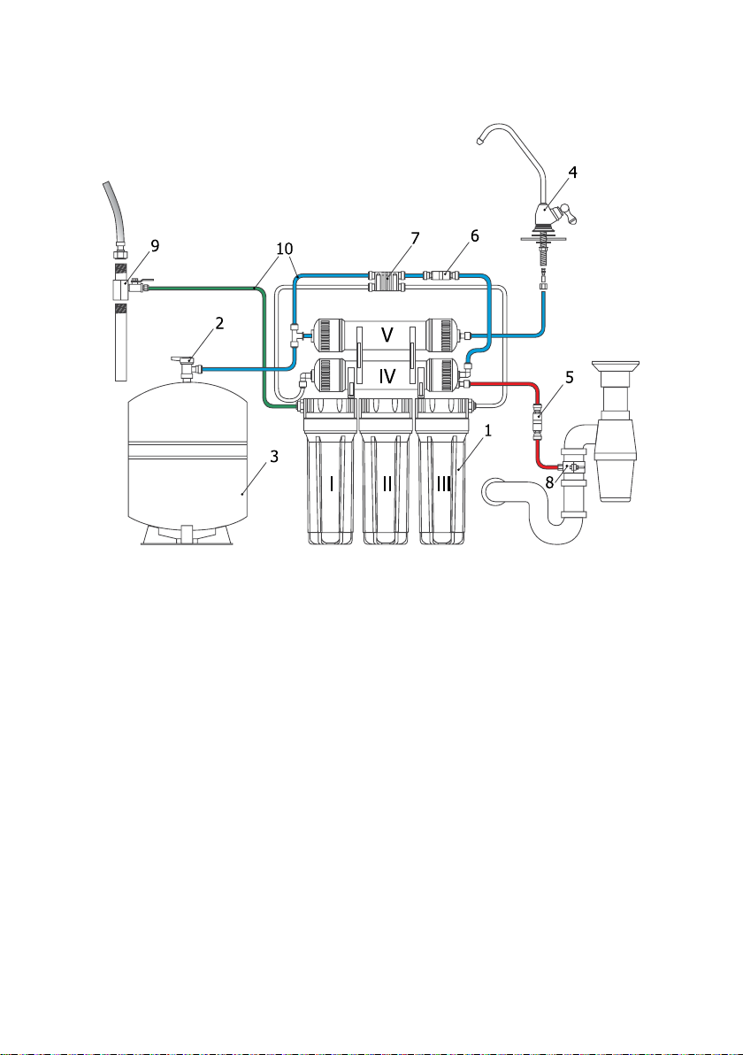
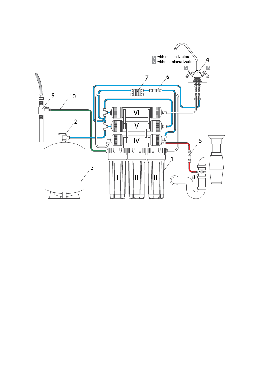
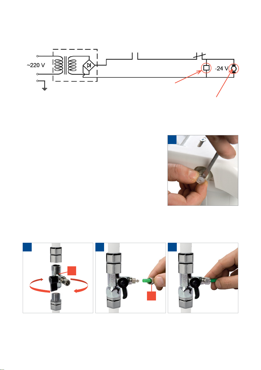
CONNECTION
RECOMMENDATIONS FOR CONNECTION AND OPERATION
the connection is carried out only by the qualied specialist or the manufacturer’s
representative;
strictly follow the manual in case of individual connection;
all lter cases were tested for sealness and hydraulic impact, that is why there is on
water inside cases of the lter;
it is not recommended to disassemble factory connections without the need.
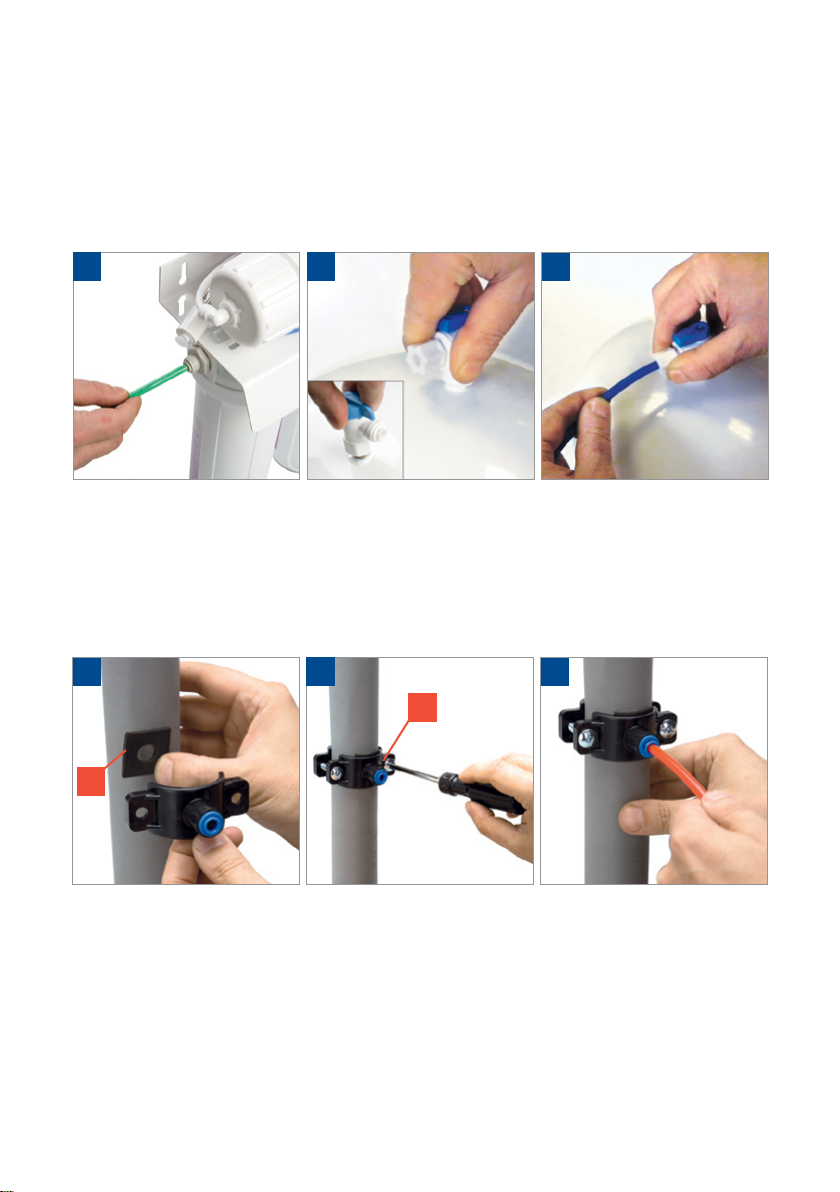
PREPARATION TO THE CONNECTION
1. Shut off the cold water feed to the connection point
(Fig.1) and discharge a pressure by opening the mixer.
2. Make sure that the lter flasks are reliably tightened*.
Tighten them, if necessary.
1
*Periodically check a reliability of the lter flasks tightness and
tighten them, if necessary.
Attention! A position of the vertical label, which is placed strictly
align the lter front center, does not guarantee the connection
leakproofness. A position of the label can be changed during
tightening of the flask screwed connection.

5
1. Cases with ltering elements on the frame ............................................. 1 set
I – a case of the mechanical lter
II, III – cases of carbon lters
IV – a case of the reverse osmosis membrane
V – a case of the carbon post-lter
2. A gate of the storage tank.......................................................................... 1 unit
3. Storage tank................................................................................................1 unit
4. Tap with clear water ................................................................................... 1 set
5. Drain flux limiter ......................................................................................... 1 unit
6. Reverse-flow valve ..................................................................................... 1 unit
7. Automatic water switch ............................................................................. 1 unit
8. Drain strap .................................................................................................. 1 set
9. Tee (adapter) with the water feed tap ....................................................... 1 unit
10. JG Pipe 1/4’’ ................................................................................................ 1 set
* The manufacturer reserves the right make small improvements of the system structure and
conguration without their reflection in this manual.
CONNECTION DIAGRAMS AND A SCOPE OF DELIVERY OF
GEYSER-ALLEGRO*

6
1. Cases with ltering elements on the frame ............................................. 1 set
I – a case of the mechanical lter
II, III – cases carbon lters
IV – a case of the reverse osmosis membrane
V – a case of the carbon post-lter
VI – the mineralizer case
2. A gate of the storage tank.......................................................................... 1 unit
3. Storage tank................................................................................................1 unit
4. Tap of clean water ...................................................................................... 1 set
5. Drain flux limiter ......................................................................................... 1 unit
6. Reverse-flow valve ..................................................................................... 1 unit
7. Automatic water switch ............................................................................. 1 unit
8. Drain strap .................................................................................................. 1 set
9. Tee (adapter) with the water feed tap ....................................................... 1 unit
10. JG Pipe 1/4’’ ................................................................................................ 1 set
CONNECTION DIAGRAMS AND A SCOPE OF DELIVERY OF
GEYSER-ALLEGRO M *
* The manufacturer reserves the right make small improvements of the system structure and
conguration without their reflection in this manual.

7
CONNECTION DIAGRAMS AND A SCOPE OF DELIVERY OF
GEYSER-ALLEGRO P *
1. Cases with ltering elements on the frame............................................... 1 set
I – a case of the mechanical lter
II, III – cases of carbon lters
IV – a case of the reverse osmosis membrane
V – a case of the carbon post-lter
2. A gate of the storage tank .......................................................................... 1 unit
3. Storage tank................................................................................................ 1 unit
4. Tap of clean water....................................................................................... 1 set
5. Drain flux limiter.......................................................................................... 1 unit
6. Reverse-flow valve...................................................................................... 1 unit
7. High pressure controller............................................................................. 1 unit
8. Drain strap................................................................................................... 1 set
9. Tee (adapter) with the water feed tap........................................................ 1 unit
10. JG Pipe 1/4’’ ................................................................................................ 1 set
11. Low pressure controller.............................................................................. 1 unit
12. Solenoid valve ............................................................................................. 1 unit
13. Pump ........................................................................................................... 1 unit
* The manufacturer reserves the right make small improvements of the system structure and
conguration without their reflection in this manual.

8
CONNECTION DIAGRAMS AND A SCOPE OF DELIVERY OF
GEYSER-ALLEGRO PM *
1. Cases with ltering elements on the frame............................................... 1 set
I – a case of the mechanical lter
II, III – cases of carbon lters
IV – a case of the reverse osmosis membrane
V – a case of the carbon post-lter
VI – the mineralizer case
2. A gate of the storage tank .......................................................................... 1 unit
3. Storage tank................................................................................................ 1 unit
4. Tap of clean water....................................................................................... 1 set
5. Drain flux limiter.......................................................................................... 1 unit
6. Reverse-flow valve...................................................................................... 1 unit
7. High pressure controller............................................................................. 1 unit
8. Drain strap................................................................................................... 1 set
9. Tee (adapter) with the water feed tap........................................................ 1 unit
10. JG Pipe 1/4’’ ................................................................................................ 1 set
11. Low pressure controller.............................................................................. 1 unit
12. Solenoid valve ............................................................................................. 1 unit
13. Pump ........................................................................................................... 1 unit
* The manufacturer reserves the right make small improvements of the system structure and
conguration without their reflection in this manual.

9
A loose end of this tube is connected to the lter input or to the low pressure controller
tee (for models with the pump) (Fig.4).
SYSTEM INSTALLATION
We recommend carry out the system installation with specialists or install it strictly in
accordance with the manual.
It is not recommended to disassemble factory
connections – the system is supplied in the assembled
condition and is tested for sealness with the high pressure.
Remove the lter from its packing box. Remove transport
plugs (!).
Install the bracket with cases (and cartridges) at a
vantage place at a height of no less than 15 cm from cases
bottom to the floor.
The system and storage tank should be installed at a
distance of no less than 1 meter from heaters.
Connection to the water conduit
The system is connected to the COLD water main line.
Make sure that the water feed to the connection point is shut off!
1. Install the tee-adapter (A) on the cold water main line and seal joints (Fig.1).
2. Insert a plastic tube into a nut (B) (Fig.2). Insert the pipe into the ball tap tting against
stop and tightly screw a nut (Fig.3).
!
31
А
2
В
ELECTRICAL SCHEME OF THE REVERSE OSMOSIS SYSTEM FOR MODELS
WITH THE PUMP
Low pressure
controller
Power supply unit
Solenoid valve
Pump electric motor
High pressure
controller

10
Drain strap installation
It is recommended to install a strap on the drain line 40 mm in diameter after the
syphon.
Drill a hole 7 mm in diameter at the place, where you plan to install the strap. If the drain
line is positioned horizontally, drill a hole on the pipe top part so that to avoid the waste
water penetration to the lter.
Remove a protecting lm from the sealing gasket.
23
E
1
D
The storage tank assembly
Remove the tank from the package. Install the tank on the support in such position, in
which the tank is more stable.
Screw a gate of the storage tank on the threaded tting (Fig.5).
Use the FUM tape for sealing connections.
Put a cap nut on the blue tube, insert a plastic grommet into the tube against stop and
screw a nut on the storage tank gate tting.
Insert a loose end of the tube to the carbon post-lter tee against stop.
Glue the gasket (D) from the strap inner side aligning simultaneously a hole in the gasket
and a hole in the strap tting (Fig.1).
Lock the strap (E) rmly on the drain line using screws aligning simultaneously holes of
the tting and the drain line (Fig.2). It is required to tighten xing screws uniformly (without
misalignment) so that both parts of the strap are placed in parallel.
Insert the red tube from the drain flux limiter (item 5, see the Connection diagram) into
the drilled hole for a length of 7-10 mm through the strap (E) (Fig.3).
56
4

11
Assemble the tap in the following order:
1. Faucet
2. Cuvette
3. Rubber gasket
4. Plastic washer
5. Metal washer
6. engraving washer
Fix the faucet on the sink. In the nut (G) pull up blue (Fig.
1). The piston (H) insert the inside tube until it stops. Slip
into the end of the tube resistant plastic ring (F) (Fig. 2).
Screw on the threaded stem of the valve nut (Fig. 3).
The mineralizer connection
Install the case on brackets and connect it with tubes, while observing the flow direction: from
the case to the output, from the output to the tap of clean water (see pp.5 and 7).
Check the reliability and correctness of all connections before the system
commissioning.
SYSTEM FLUSH
In order to prevent the carbon dust penetration to the membrane element and other
components of the system, it is recommended to wash carbon cartridges in case of the
rst system commissioning, as well as at replacement of replaceable components of the
water preliminary purication.
Turn off the storage tank tap, open the tap of clean water and water feed tap. Water
will begin to drop from the tap of clean water in 3-5 minutes. Leave the tap of clean water
opened for 10 minutes, then close it and open the tank tap for several hours. A pressure
will be generated in the tank.
ATTENTION! Do not drink the water obtained during the rst tank lling. Open the
tank with clean water after the tank lling, drain the WHOLE tank and rell it as described
above. This will take several hours depending on a pressure in the supply main. After this
the water can be drunk.
The system flush is required:
- after long (2 weeks) interruptions of usage;
- after maintenance (for example, replacement of cartridges)
After the lter commissioning the water color after purication can be muddy (turbid).
It is conditional upon air bubbles superseded from the lter. It is not a failure. Generally
these air bubbles disappear after the lter use.
32
F
1
G
Connection of the tap of clean water
Drill a hole 12 mm in diameter in the washer.
2
4
1
5
3
6
H

12
SYSTEM MAINTENANCE
Replacement of cartridges of I, II, III stage
Turn the water off at the input and in the storage tank. Open the tank with clean water
to release a pressure in the system. Remove the case flask using a wrench (I, II, III stages)
and replace the corresponding cartridge. It is recommended to grease a sealing ring with
the food grade silicone or petroleum jelly before reinstallation (do not confuse with a sealing
agent!). Install the flask into position and tighten with a wrench. Check the system for the
sealness.
Before using flash the preliminary purication system. For this purpose detach the tube
from the membrane case and intercept the flow of water. Wait for the effluent water to be
clean and assemble the lter in the inverse order.
2 31
Membrane replacement
The membrane is delivered vacuum-sealed for its preservation during transportation and
storage. Before installation remove the package, shut off a tap of the tank and the water feed
tap, open the tap of clean water and detach tubes of the VI case connection (1). Withdraw the
old membrane (2). Install the new membrane and grease seals with the food grade silicone
or petroleum jelly (3). Screw the membrane case cap. Use only recommended membranes
for the replacement.
Replacement of the carbon post-lter and mineralizer
Detach tubes from the case (1), replace the post-lter with the new one, connect tubes.
Replacement of the mineralizer is carried out in the same way.
Note. Do not confuse the water input and output on the post-lter. The water flow
direction is indicated by the arrow on the post-lter case.
2 31
It is recommended to shut off the source water feed, disconnect the system from the
power supply and drain the puried water from the storage tank in case of a long (more than
1 week) interruption of the system usage.

13
LIST OF POSSIBLE FAILURES AND METHODS OF THEIR ELIMINATION
POTENTIAL
FAILURE REASONS ELIMINATION METHOD NOTE
The white
water flows
from the
tap of clean
water
There is the air in the
system
The air will gradually
be out of the system
This situation is considered
normal during the new system
commissioning or the replacement
of ltering modules
The water
does not
flow from
the tap or
flows very
slowly
The system has just
started to operate Wait for 4-6 hours
The tank lling can be from 4
hours depending on the water
temperature and the pressure in
the main.
The carbon post-lter
has exhausted its
resource
Replace the post-
lter Contact the customer service
There is no the
excessive air pressure
in the storage tank
Pressurize the
membrane tank to
0.5 atm.
Contact the customer service
The water
does not
inflow to the
storage tank
or inflows
slowly.
Noise, knock
of the pump
Low pressure in the
supply main (less than
3 atm.)
Install the facility
increasing a
pressure
The water intake speed to the
storage tank (after the membrane)
should be 75-100 ml/min
The resource of
replaceable elements
of the water preliminary
purication is used up
Replace
Cartridges can be quickly clogged
due to a large-scale waste
dumping to the water conduit or
because the water is constantly
flows through them, i. e. a drain
flux is not shut
The reverse-osmosis
membrane resource is
used up
Replace
The membrane can be clogged
sufciently quickly, if it operates
on the hard water
The automatic switch is
malfunctioning Replace Contact the customer service
Obstructions in pipes Check and eliminate
The storage tank gate
is closed Open
The tap at the lter
input is closed Open
The pump is
malfunctioning Replace
A pressure behind the working
pump should not be more than 7
atm.
The reverse-flow valve
is malfunctioning Replace Contact the customer service
The high pressure
controller is
malfunctioning
Replace Contact the customer service
There is no contact in
electrical connections
Check electrical
connections
ATTENTION!
During replacement it is recommended to use replaceable components Geyser. Non-
compliance with this requirement can lead to the alteration of the water-purication
system functional and technical characteristics.

14
Water leak Fittings are not tightened Tighten connections
There is too little
water outflowing
from the storage
tank
The system has just started to
operate
The tank lling can
be from 4 hours to 6
hours depending on
the water temperature
and the pressure in
the main
The excessive pressure is low
in the storage tank
Increase the
pressure
The normal pressure
in the empty tank
should be 0.4-0.5
atm.
The storage tank
is full, but the
water flows to
the drainage
The pressure in the supply
main is reduced, and, as a
consequence, the automatic
switch does not operate
Install the facility
increasing a
pressure
The automatic switch
steadily operates at
the pressure of more
than 2.5 atm.
The automatic switch is
malfunctioning Replace
The automatic switch
cannot operate due to
a production defect
Water has a taste
or foul smell
Water stagnation in the lter or
the storage tank for a long time
Wash the system
with water and rell
the tank
The carbon post-lter has
exhausted its resource Replace
Remainder of a preservative
agent in the storage tank
Drain water from the
tank and rell it
The drain flux
is not shut after
lling of the
storage tank
The pressure in the supply
main is reduced, and, as a
consequence, the automatic
switch does not operate
Install the pressure
increase unit
The automatic switch
steadily operates at
the pressure of more
than 2.5 atm.
The automatic switch is
malfunctioning Replace
The automatic switch
cannot operate due to
a production defect
ADDITIONS
The automatic switch shuts the source water supply to the osmosis at the maximum
lling of the storage tank that prevents water permanent drain to the drainage.
The low pressure controller is used for disconnecting the reverse osmosis system at a
drop in pressure in the water conduit.
The high pressure controller is used for disconnecting the reverse osmosis system at the
storage tank lling with the puried water.
The drain flux limiter maintains the required pressure on the reverse-osmosis membrane
by limiting the wasted water outflow to the drainage.

15
WARRANTY CARD
QUESTIONS CONCERNING THE WARRANTY MAINTENANCE SHOULD BE REFERRED TO:
Issuing date
The trading organization shall ll
Sale date
Stamp of a store
WARRANTY LIABILITIES
The warranty period of the lter operation is years from the sale date. In the lack of the
sale date and a stamp of the trading organization the warranty period shall commence at
the date of the lter manufacture. The warranty does not apply to replaceable components.
Their service life specied on page 3. In case of detection of manufacturing defects
cartridges are replaced only after the expertise carried out by the customer service’s
representatives.
The manufacturer declines any liability for the lter’s work and possible consequences
in cases, if:
the lter and its components have mechanical damages;
requirements of this manual were not observed during connection and operation;
cartridges are worn out;
the lter was used for purposes other than intended (for purication of subversive
liquids).
The lter’s service life is 10 years. The maintenance and post-warranty repair are
carried out by the manufacturer or its destination representatives.
PRECAUTIONARY MEASURES. STORAGE AND TRANSPORTATION
Protect the lter from impacts, falls, exposure to direct sunlight and negative temperatures.
The transportation of the lter is acceptable in any closed transportation vehicles (except
for unheated sections of planes) in accordance with cargo transportation rules and norms
applicable for this transport type.
The lter is stored packed, at a distance of not less than 1 m from heaters at the temperature
of from +4° to +40°С.
The exposure to oversprays, deleterious and odorous substances is not allowed.

16
More on the website www.geizer.com
aquachief
The water-purication system
for country houses
UNIQUE SOLUTION:
Removal of iron and hardness salts (scale) by one
ltering media of Ecotar.
IT IS FAVORABLE AND SIMPLY TO USE:
Expensive reagents are not required for the media
recovery. The regeneration is carried out using table
salt. Drain waters are harmless for septic tanks.
SPACE SAVING IN A HOUSE:
Geyser Aquachief occupies 2 times less
space, than systems operating at usual lling
loadings.
INDIVIDUAL APPROACH:
The variety of Ecotar media allows easily
adjusting of Geyser Aquachief for water
purication in every region.
MANUFACTURER: “AKVATORIA” LTD
This manual suits for next models
3
Table of contents
Other Geyser Water Filtration System manuals
Popular Water Filtration System manuals by other brands

Vimar
Vimar elvox 692S Installation and operation manual

Newa Pond
Newa Pond PURE LIGHT UV-C advance Instructions and guarantee

Everpure
Everpure Water Filter CB20-302E Installation and operating instructions

Hydro
Hydro AGF-15 Operating and maintenance manual

Sharp
Sharp FZ-A60HFU Product information

smartmi
smartmi 2 user manual