Prozone Water Products Complete Sanitation System 15 User manual
T.O3 NATURAL TECHNOLOGY
Reduces Chemical Usage,
Improves Sanitation, Eliminates Odors
Produces Crystal Clear Water
Copyright 2007
202067
CSS 15 — Ozone/Salt Chlorinator
Prozone has combined ozone and salt together in one
Complete Sanitation System for your pool
Prozone Water Products: 3004 11th Ave - Huntsville, AL - 35805 Phone: 256-539-4570 Website: www.prozoneint.com
2IMPORTANT SAFETY INSTRUCTIONS
Read and Follow All Safety Instructions
· Read and be familiar with this manual before installing, operating, or performing maintenance on
the CSS 15.
· The CSS 15 is a universal voltage system.
· The CSS 15 must be installed in accordance with the installation instructions and diagrams
provided in this manual.
· The CSS 15 power supply must be mounted vertically on a flat surface and a minimum of 5 feet
from the pool.
· Use only the power cord provided with the CSS 15.
· Canada and some other regional codes mandate the use of GFCI protected circuits. If installation
is completed by a licensed electrician or pool equipment installer, they will be required to verify this
requirement for your area and comply during installation
WARNING: Disconnect all power to pool equipment prior to installation, maintenance,
or removal of the CSS 15.
WARNING: Do not permit children to operate this product
WARNING: To avoid risk of electric shock, fire, or injury, service should only be performed
by a qualified pool service professional.
WARNING: Installation must be performed in accordance with the National Electric Code
and any applicable local or state installation codes.
WARNING: When mixing acid with water, ALWAYS ADD ACID TO WATER, NEVER
WATER TO ACID.
SAVE THESE INSTRUCTIONS
C S S 1 5
2Downloaded from www.Manualslib.com manuals search engine

3
C S S 1 5
Table of Contents
Section1:ProductInformationSection2:InstallationSection3:PoolPreparationSection4:OperationSection5:ChlorineGeneratorCellFunction&MaintenanceSection6:Winterization&SpringStart-UpSection8:TroubleShootingGuide1.1RecordedInformationSheets1.2Introduction1.3CustomerResponsibilites1.4HowDoesItWork2.1InstallationGuidelines2.2VerifyContents2.3QuickStartInstallationGuide2.4SaddleClampInstallationGuide3.1Start-UpProcedures3.2PreparingYourPool3.3AddingSalt3.4BalancePoolchemicals3.5PoolCirculation3.6PoolPreparationWarnings4.1SystemOperation4.2ChlorineAdjustment5.1CellMaintenance5.2CalciumDeposits5.3AcidWashInstructions1.4aDescription1.4bSpecifications3.2aTestingThePoolWater3.2bBackyardTesting3.2cProfessionalTesting44&55566777781112121212121212131313141414151515151516Page
4Record The Following Information and Save For Future Use
Visit us on the Web
www.prozoneint.com
Manufactured by
Prozone Water Products
3004 11th Ave.
Huntsville, AL 35805
C S S 1 5
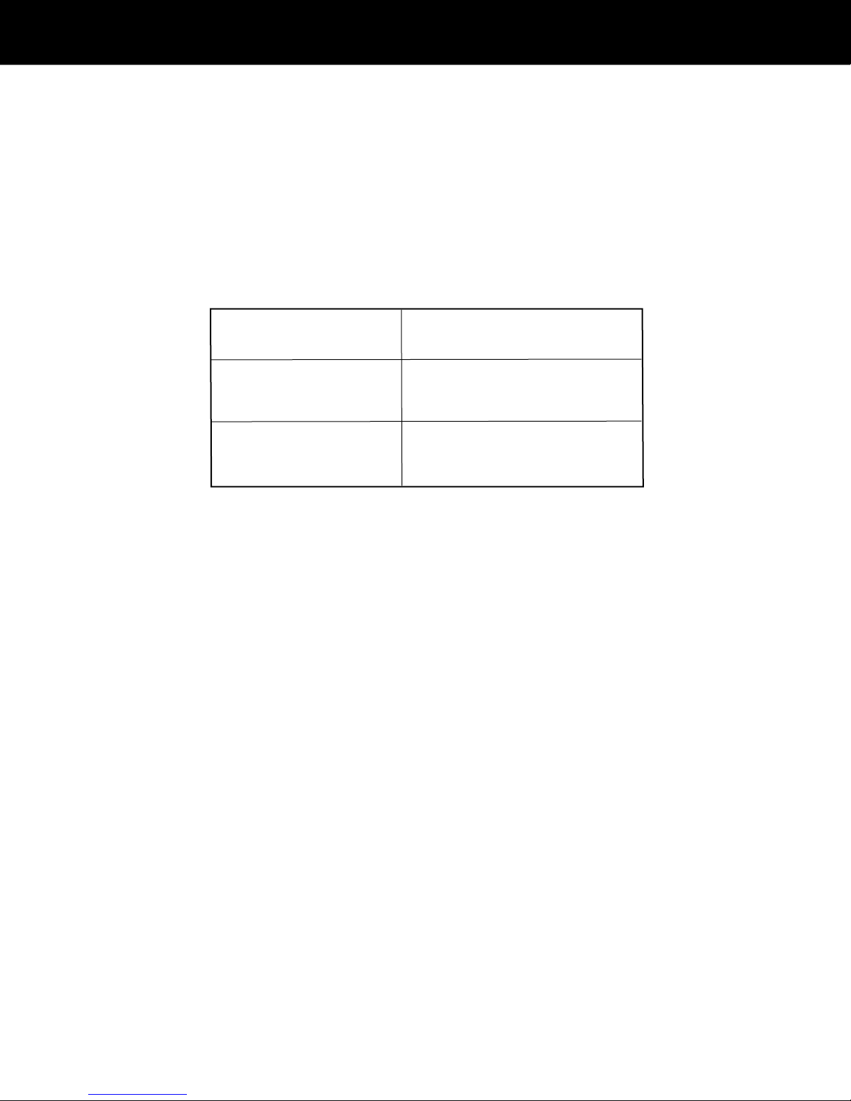
Installer: Date of Installation:
Control Box Control Box
Model Number: CSS 15 Serial Number:
Cell Cell
Model Number Serial Number:
Section 1 Product Information

5
C S S 1 5
1.2 Introduction
Congratulations! You have purchased on of the most technologically advanced Pool Sanitation Systems in the world. The CSS 15 Ozone/Salt
Chlorine Generator (Advanced Oxidation Processor ™) is the most powerful solution for Sanitation and Oxidation requirements in your pool,
the benefits of which will be evident from the very first time you use it and for many years to come.
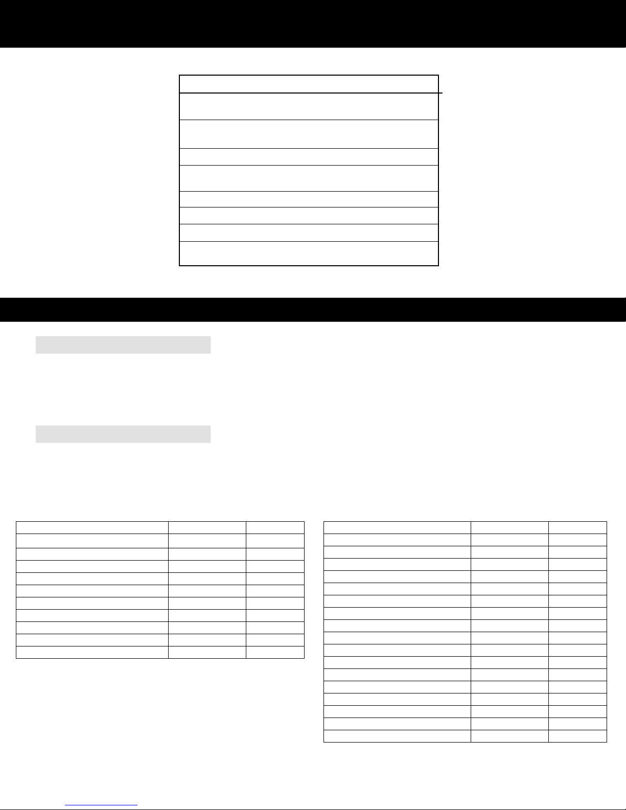
1.3 Customer Responsibilities
Record the Following Information at Initial Installation of your CSS 15 Unit
Proper Water Chemistry is Important to Protect Your Valuable Investment
The above information will be required for Technical Support conversations.
This information must be provided in the event a warranty claim is requested.
Date Levels
pH
Alkalinity
TDS (Total Dissolved Solids)
Cyanuric Acid (Stabilizer)
Salt Levels
Free Chlorine
Calcium Hardness
Metals
Nitrates / Phosphates
Saturation Index
Section 1 Product Information
Start-Up Water Analysis
6◊ Complete and mail in your warranty page included in this manual. Your warranty is not valid until this product is registered, and must be
completed within 30 days of installation. Keep your original sales receipt in case product needs to be serviced.
◊ Proper water balance must be maintained to protect your valuable investment.
◊ Ensure that your CSS 15 unit has been properly installed
◊ Check the Chlorine Generator Cell often; follow Cell Maintenance instructions in this manual located in Section 5
◊ Increase Chlorine Production percentage as warm temperatures increase.
(Hot weather conditions make it more difficult to maintain proper chlorine levels)
∆ WARNING: Failure to follow these maintenance instructions, and all other specified operating procedures might void the warranty of this product.
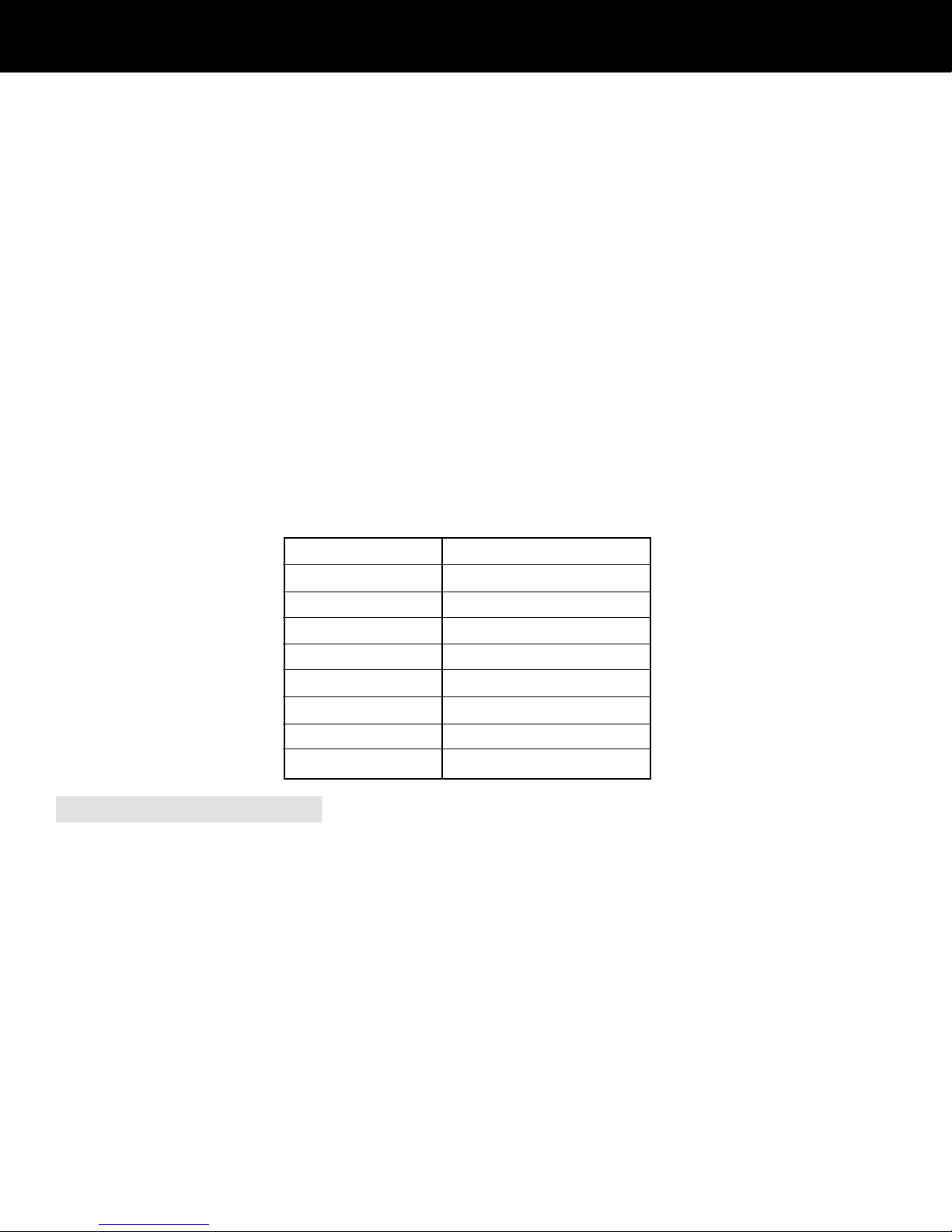
The Table below summarizes the levels that are recommended by The Association of Pool and Spa Professionals (APSP). It is important to
maintain these levels in order to prevent corrosion or scaling and to ensure maximum enjoyment of the pool. Test your water periodically. Take a
water sample in to be professionally tested by a Pool and Spa Professional at least once a month. Be sure to tell your local Pool Store that you
are using a Complete Sanitation System, Ozone/Salt Chlorine Generator Combination System.
1D How Does it Work
Description:
Your CSS 15 System produces both ozone and chlorine. The Ozone Generator produces ozone with light energy, the way the sun does. Therefore, it
is only emitting pure O3 ozone that has no harmful by-products, unlike other ozone generators that use corona technology which
produce nitrous acid compounds and other harmful byproducts. Ozone is a molecule of oxygen that is formed when three atoms of oxygen are
bound together instead of the normal two atoms. The extra oxygen atom makes ozone the most powerful, naturally occurring oxidizer and sanitizer
readily available. Pioneers of the original ozone generator cartridge, produced the first Ultraviolet Ozone Generating cartridge in 1977 for the
swimming pool and spa industry.
The O3, naturally produced ozone, generated by the CSS 15 System serves as the primary sanitizer and oxidizer, however, a small residual of free
available chlorine is required at all times to control algae growth and provide a residual sanitizer requirement.
The CSS 15 System provides the necessary chlorine residual for your pool. A measured amount of pool salt is dissolved in the pool water. The
Chlorine is made by passing a very low voltage electric current through the salt water as it flows through the Cell and back in to the pool.
The CSS 15 System (Advanced Oxidation Processor™) produces and combines ozone and chlorine. These super oxide compounds, even stronger
oxidizers than ozone or chlorine alone, are injected in to the pool water through a patented Venturi Bypass Installation process.
While the initial costs of the system may seem sizable, the savings begin immediately. Using your CSS 15, you will eliminate almost all chlorine
purchases. You will produce chlorine in your own backyard for pennies a gallon. In addition to the cost savings, you have eliminated the need to
transport and store potent chlorine oxidizers and sanitizers. In most parts of the country, the costs are recovered in three to four seasons.
C S S 1 5
pH 7.2 to 7.6
Alkalinity 80 – 120 ppm
TDS Less than 1,000 Excluding Salt
Cyanuric Acid 30 – 70 ppm
Salt Levels 2500 to 3000 ppm
Free Chlorine .5 to 1.5 ppm
Calcium Hardness 60 to 400 ppm
Metals 0 ppm
Nitrates / Phosphates <30 ppm
Section 1 Product Information
◊ Refer to our website for for information on Basic Pool Chemistry at: www.prozoneint.com/manuals.php
7Specifications:
2.1 Installation Guidelines
◊ The CSS 15 must be correctly installed or your system may not work properly and the warranty will be voided.
◊ The CSS 15 should be installed on residential pools only.
◊ A qualified swimming pool professional and certified electrician must install the CSS 15.
2.2 Verify Contents
Verify that you have the following parts prior to starting installation.
Z36 Installation Kit (For existing pool installation)
Refer to this list when ordering replacement parts
CSS 15
Power Requirements Dual Voltage
90 - 270VAC/50/60Hz
Operating Temperature Air: 25°F to 140°F
Water: 59°F to 110°F
Ozone Specifications .4g/hr @ 110°F @ 60% RH
Salinity PPM 1500 to 4000 PPM
2500 PPM nominal
Chlorinator Production 20 g/hr = 1 lb/day
Pool Capacity 30,000 Gallons
Water Flow Rate 1 to 12 gpm
Dimension Specifications 15” X 10” X 6.5”
20 lbs.
C S S 1 5
Section 2 Product Installation
Section 1 Product Information
Description
Part Number
Quantity
684 Venturi Injector Assembly
600061
1
Plastic Clamp ½”
20185
3
Metal Clamp 1-¼”
20067
4
Polybraid Hose ¼”
20260
120”
Polybraid Hose ¾”
201969
120”
Ball Valve 2”
20242
1
PVC Fitting 2”SP x 1-½”SL
201114
6
PVC Fitting 2”SL x ¾”FPT
201095
2
PVC Fitting ¾”MPT x HB
20678
2
Description
Part Number
Quantity
684 Venturi Injector Assembly
600233
1
Plastic Clamp ½”
20185
3
Metal Clamp 1-¼”
20067
4
Polybraid Hose ¼”
20260
120”
Polybraid Hose ¾”
201207
120”
Ball Valve 2”
20242
1
PVC Fitting 2”SP x 1-½”SL
201114
2
Saddle Clamp, Outer Top
201155-4
2
Saddle Clamp, Outer Bottom
201155
2
Saddle Clamp, Inner Top
201155-2
2
Saddle Clamp, Inner Bottom
201155-3
2
Saddle Clamp Gasket
400076
2
Saddle Clamp Bushing
201155-5
2
Screw #14 x 1-½” PPMS
201863
4
Nut ¼-20
20703
4
PVC Pipe ½” x 3”
20314
1
Z43 Installation Kit (For new pool installation)
Refer to this list when ordering replacement parts

8
C S S 1 5
2.3 Quick Start Installation Guide
Before installing this product, turn pump off
CSS 15 Mounting Instructions
· Your CSS 15 can be mounted outside near the pump and filter, or inside a pool equipment house or basement
· There is a mounting bracket at the top of the Control Box.
· Use appropriate mounting screws and hardware (not included) for the type of material you will be mounting to,
(brick, siding, concrete, etc)
· Make sure the Control Box is mounted in the vertical position, level, with no obstruction of airflow.
· Control Box should be at least 4 feet above ground, preferably higher than filter.
Electrical System Connection
New Pool Installation
(Must be installed by a qualified electrician)
· Your CSS 15 is a universal voltage system. It is preferable that this unit be wired so that it comes on when your circulation pump is
running and off when pump is off.
· Your CSS 15 comes completely assembled, with the Chlorine Generator leads connected
· Do not add salt to the pool for at least 2 weeks, allow your pool surface to completely cure and harden.
· You may turn on your Control Box and allow water to flow through the cell, (This will not damage the cell).
· Run your CSS 15 while the pump is running so your new Ozone System can oxidize and purify your pool water.
· It may be necessary to add chlorine to pool water during this process. After pool surface is completely cured, refer to manual and add
appropriate amount of salt.
Section 2 Product Installation

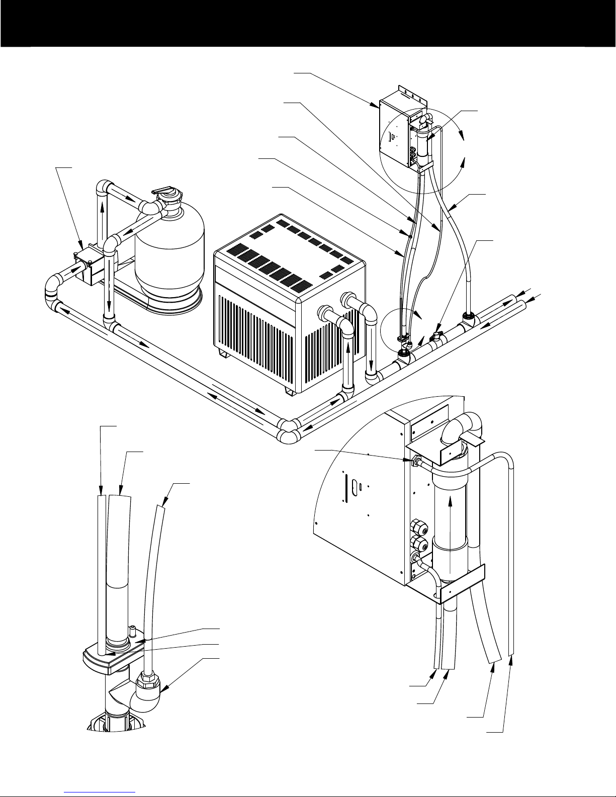
9Bypass Installation Instructions
· Install the first Tee fitting (figure A) after the Filter and/or Heater
using PVC cement. (See diagram on page10)
· Screw Injector/Injector Bypass Assembly (figure B) in to top of Tee fitting,
using plumbers tape.
· Measure and cut the ¾” hose to fit distance between Injector and
bottom of Chlorine Generator Cell See (See diagram on page 10)
· Place two metal clamps on ¾” hose.
· Attach one end of ¾” hose to top of Injector, tighten with metal clamp
· Attach other end of ¾” hose to bottom of Chlorine Generator Cell, tighten with metal clamp
C S S 1 5
Section 2 Product Installation
Injector/Injector Bypass Assembly
Tee Fitting
(B)
(A)
Grounding/bonding lug
The grounding/bonding lug on the bottom of the unit MUST be connected using
a 6AWG solid copper conductor (not included) to the equipotential bonding grid
(common ground point) of the swimming pool, along with any/all other pool
equipment. Generally, this equipotential bonding grid can be the structural
reinforcing steel of a concrete pool, the wall of a bolted/welded metal pool, or
similar assembly. It is highly recommended to install a sacrificial anode, somewhere
in the pool, (usually attached to the ladder).
Grounding lug
· Install the second Tee fitting (figure C), using PVC cement, after the Ball Valve.
· Screw grey barbed fitting (figure D) in to top of Tee fitting, using plumbers tape
.
· Place two metal clamps on remaining ¾” hose
· Attach one end of remaining length of ¾” hose to top of Chlorine Generator Cell
and tighten with metal clamp. (See diagram on page 10).
·
Attach other end of ¾” hose to barb fitting (See figure D) and tighten metal clamp.
Insure hose is held in place and will not kink in any way.
Ozone System Connection (See diagram on page 10)
· Place two black plastic hose clamps on ¼” braided hose.
·
Attach one end of braided hose to open port on top of Injector and tighten clamp.
· Attach the other end of ¼” braided hose to bottom of Check Valve and tighten clamp.
(D) ¾” Hose
Grey Barbed Fitting
Tee Fitting
(C)
Install the Ball Valve, (See diagram on page 10).
·
wolF
re
t
a
W
Injector Open Port
¾” Hose
¼” Hose
Metal Clamp
Black Plastic Clamp
wolF enoz
O
(Marked #1)
10
C S S 1 5
Section 2 Product Installation
!"#$
%&'(
#
%&'(
'(
)'(
%%
* !"#$
+)%%
%%,
-)./0
!"#$)
* !"#$
%*1
%((/)0
%&'(
+)%%
2-3*0
!"#
$
%
%&'()*
+ ,
$
&-
%
!"#$
%
&'"()
* +
%
,#"-#.
% /0
CSS
Ball Valve
Saddle Clamp
Assembly
Saddle Clamp
Assembly
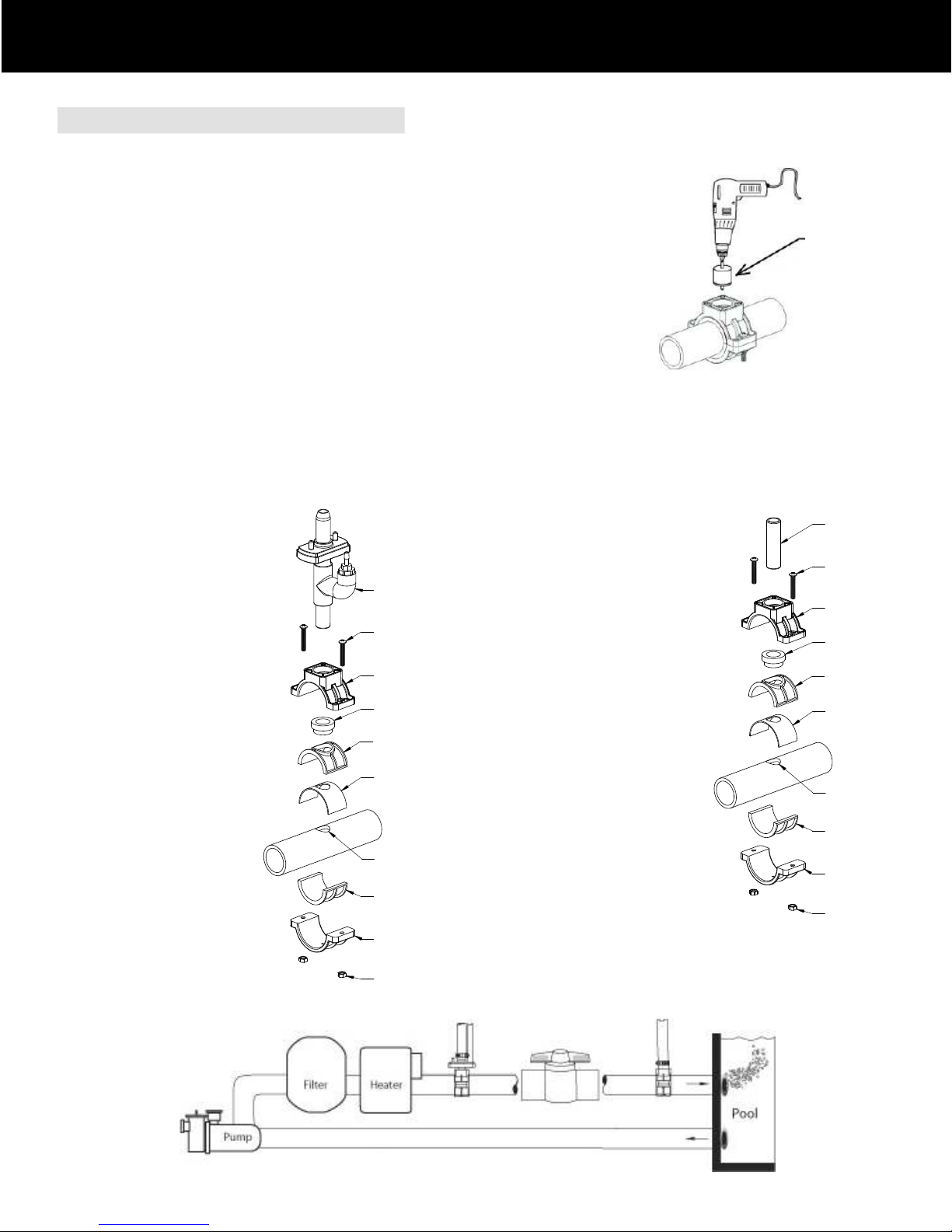
1. Turn pump OFF.
2. Locate section of existing plumbing in which you choose to install the entrance leg of the bypass.
Location should be in any accessible area after the pump, filter, and heater.
3. Install Saddle Clamp Top & Bottom, (and adapters if needed), without Bushing
and Venturi Injector Assembly.
NOTICE This will be used as a guide for your installation hole.
4. Drill 7/8” hole through one wall of pipe, using power drill.
CAUTION: Do not drill too deep to avoid penetrating the opposite side in the plumbing.
5. Install Ball Valve between the entrance point and the exit point of the Saddle Clamp bypass.
6. Repeat steps 1, 2, 3 and 4 for exit of the bypass. Remove both Saddle Clamp Assemblies.
CAUTION: The bypass exit should ALWAYS be after the heater or damage may occur to the heater.
7. Re-mount Saddle Clamp assemblies on both Entrance and Exit bypass locations (See Figures 6, 7 & 8).
Note: For 2” pipe, do not use 1-1/2” adapters and gasket and turn Bushings so small end points toward Injector Assembly (for Entrance)
or PVC Pipe (20314)(for Exit).
For bypass Entrance, (before Ball Valve)
Using 1-1/2” pipe, Assemble:
Venturi Injector Assembly (Note direction)
Saddle Clamp Top & Bottom
Top & Bottom Adapters
Bushing (Note direction)
Gasket
Screws (2)
Nuts (2)
(Figure 6)
For bypass Exit, (after Ball Valve)
Using 1-1/2” pipe, Assemble:
PVC Pipe
Saddle Clamp Top & Bottom
Top & Bottom Adapters
Bushing (Note direction)
Gasket
Screws (2)
Nuts (2)
(Figure 7)
Installation
C S S 1 5
2.4 Saddle Clamp Installation Guide
Section 2 Product Installation
117/8” Dia. Hole Saw
(Figure 8)

12
C S S 1 5
Section 3 Pool Preparation
Establishing Water Balance
While the CSS 15 systems are designed to reduce the amount of chemical care — it does not eliminate the need for water balance
Understanding how the unit fits into overall pool care is extremely important. Before starting your new sanitation system, you will need to bring a
water sample to your local pool dealer for a full analysis.
There are two stages to clean, clear, safe water.
1. Backyard Testing: Your pool water should be checked one to two times per week for pH, Chlorine, and salinity (salt).
a. pH should be between 7.2 and 7.6. Any readings outside of this range needs to be corrected immediately.
b. Free chlorine should be between .5 and 1.5 ppm (parts per million). Chlorine levels that are too high may require
an output adjustment on your system. Chlorine levels that are too low may require salt addition or adjustment of
the system.
c. Salinity should be between 2500 ppm and 3000 ppm. Levels that are too low will result in inadequate chlorine
production, levels that are too high, (>3,300 ppm), will result in CSS system shutting down.
2. Professional Testing: A water sample needs to be brought to your Professional Pool dealer once a month to have the overall
water balance checked.
a. In addition to verifying your readings, the dealer will also test for Alkalinity, Calcium, Stabilizer, and the presence of
any unwanted minerals like iron and copper. Electronic salinity testing is critical to CSS system performance.
∆ WARNING: Failing to properly balance your water may result in damage to the CSS 15 unit as well as the pool surface and equipment. Bathers
will experience discomfort. Note: This and all related product warranties do not cover failure or damage caused by improper poor water balance.
3.2 Preparing Your Pool
◊ Test and balance the pool water. Pool water must be at the proper salinity level, and chemically balanced before operating the
CSS 15. Refer to Table on page 6 for required levels. Pools should be balanced in this order:
3.1 Water Testing 1)BalancepHto7.2-7.62)ShockpoolwithChlorineto20PPM3)Brushpool4)Vacuumandbackflushtodump5)Addrequiredsalt6)Wait4hoursforpooltoequalize7)BalancepH8)Runcirculation/CSSsystemfor48hoursandcheckchemicallevels9)CheckFilter3.3 Adding Salt
◊ Test the salt level of your pool before calculating the salt requirement, particularly if a salt chlorine generator has been used,
or sodium chloride has been previously added to the pool water. It is best to use an electronic measuring device rather than test
strips for accurate measurement. If pool has excessive salt or salt is not properly mixed, system may eventually shut down
and must be re-started by turning power switch off and on again. Salt should be thoroughly dissolved before turning system on.
When adding salt after pool has had initial bank, it is best to dissolve salt prior to adding it to the pool. Salt should be added per
the following formula to meet concentration requirements, providing the pool water has not already had any salt added to it.
• Rectangular – Length x Width x Average Depth x 7.5 (for gallons) or x 1000 for liters.
• Round – Diameter x Diameter x Average Depth x 5.9 (for gallons) or x 785 for liters.
• Oval – Length x Width x Average Depth x 6.7 (for gallons) or x 893 for liters.
Pool gallons can be determined from the following formulas:
21 pounds of salt for every 1,000 gallons of pool water

C S S 1 5
3.4 Balance Pool Chemicals
◊ Add Cyanuric acid (chlorine stabilizer) at the same time you add salt. Cyanuric acid helps maintain chlorine levels and it is
required to maintain chlorine levels during hot weather. A pH buffer can also be added at this time. The appropriated
concentration of Cyanuric acid is from 30 to 70 ppm.
◊ Before turning on the CSS 15, add Chlorine Shock to pool to reach 20 ppm for initial start up.
Run the pool pump and Chlorine Generator for a minimum of 12 hours a day. The actual run time will be affected by the
chlorine demand from the environment or bathers.
◊ The initial set up percentage of chlorine should be set at 50% for the first 3 to 5 days. Test and adjust the chlorine percentage
until the chlorine requirement stabilizes and maintains 0.5 to 1.5 ppm of free chlorine.
◊ If the CSS 15 is being installed on a new plaster pool, do not add salt for 2 to 3 weeks after pool has been filled to help
protect plaster, and to allow time for the plaster to cure. Follow your pool builder’s suggestions on cure time allowance.
You may run your new CSS 15 system without salt in the pool. It will not harm the system, but will not generate chlorine until salt has been added.
The patented Venturi Bypass Installation allows Ozone to flow in to the pool water. Ozone helps in the hardening process for plaster and gunite pools.
Section 3 Pool Preparation
13In order for your system to produce chlorine and effectively inject ozone in to the water, the circulation system must operate at optimum levels. Poor
water flow, or short operating cycles will hamper the ability of the CSS 15 to work properly. Below are some of the guidelines for system operation:
· The pool circulation/CSS system should operate a minimum of 12 hours per day. Running the system during daylight hours is best. Minimum of
8 hours continuously during the day; 4 more hours at night.
· The filter should be cleaned or backwashed as described in the equipment manufacturer’s manual. Filters that become clogged with debris will
not allow proper water flow and may damage pool equipment including the CSS 15 chlorine generator.
· Skimmer and Pump baskets MUST be emptied regularly to keep the circulation system operating and prevent blockage.
· Debris should be removed quickly from the pool to prevent chlorine demand situations.
· Periodic brushing of pool surfaces prevents algae from growing and diminishing the effectiveness of the pools filtration and sanitation systems.
3.6 Pool Preparation Warnings
∆ WARNING: Do not use Copper or Bromine based algaecide products in your pool when the CSS 15 is installed
∆ WARNING: Always disconnect automatic pool cleaners before adding salt. Salt must be completely dissolved before
turning on the pool cleaner.
∆ WARNING: Baquacil (Biguanide) pools must be drained and refilled with fresh water prior to using the CSS 15.
∆ WARNING: Use swimming pool grade salt ONLY (low mineral content sodium chloride)
∆ WARNING: Do not attempt to add salt via the skimmer, this could damage the filter and pump. Keep the pump
operating during this process.
3.5 Pool Circulation
14
C S S 1 5
Section 4 Operation
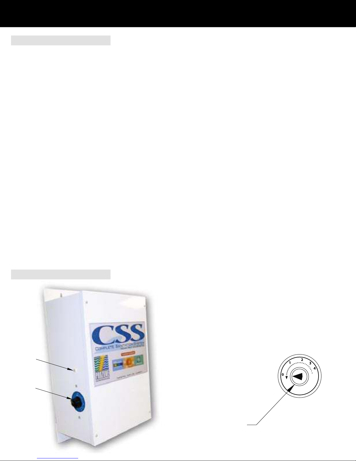
Chlorine Output Dial
Chlorine Output Dial
Power Indicator Light
4.1 System Operation
The recommended run time to generate adequate amounts of chlorine is 12 hours per day. 8 hours continuously during the day; 4 more hours at night.
Increased run times are recommended for highly loaded pools. The system will generate chlorine and ozone ONLY when the pool pump is running.
After break point chlorination and as chlorine levels off at 1 ppm, run system for 48 hours or until the chlorine level stabilizes at 1 ppm. Since your CSS
system also generates ozone, (the primary sanitizer/oxidizer), 0.5 free chlorine is all that is necessary when running the unit for 12 hours per day.
The CSS System is designed to produce a low level of chlorine that ensures the pool has adequate disinfection. This quantity of chlorine can be
as much as 90 percent less than what is required in a chlorine-only pool with no ozonator.
Normal test kits measure chlorine residual (combined chlorine, which is chlorine combined with bather load). Since ozone will normally keep bather
load at very low levels, combined chlorines will be at very low levels, making detection difficult. For water testing, DPD liquid test kits work the best, as
opposed to test strips. To get an accurate chlorine reading, a water sample should be taken to your pool/spa dealer for testing (test strips will not be
accurate enough for this). Water should be tested every week to maintain maximum water quality and enjoyment.
Salt chlorine generators may naturally increase the pH of the spa. Monitor pH regularly and adjust if it is not between 7.2 and 7.6.
NOTE: The pH value is a very important factor for ensuring maximum chlorine readings. As pH increases above 8.0, chlorine readings will decrease
rapidly. pH MUST be kept between 7.2 and 7.6. Test weekly!
Water with high calcium levels will result in scaling of the Chlorine Generator Cell plates (high pH will worsen the effect of high calcium).
Break-point chlorination is required periodically (normally about every 30-60 days) using dichloride. DO NOT use non-chlorine shock or calcium hypo-chloride.
Lightly shocking the pool is not necessary, and not recommended.
Salt level should be checked weekly, using an electronic meter, by taking a water sample to your pool/spa dealer and maintained between 2,500 ppm
and 3,000 ppm.. Salt should be pre-dissolved prior to adding to the pool and system should be turned off. Brush pool thoroughly before restarting system.
If salt level is higher then 3,300 ppm, drain pool a few inches and replenish with fresh water until proper level is reached.
Brush pool thoroughly at least once a week.
Chlorine Generator Cell should be checked periodically for blockages or obstructions and cleaned as necessary.
4.2 Chlorine Adjustment
Adjust chlorine output dial as needed to maintain chlorine level between
0.5 ppm and 1.5 ppm. Higher bather load and/or elevated ambient temperature
may require chlorine output to be increased.

15
C S S 1 5
5.1 Cell Maintenance
Inspect the Cell plates once a week to ensure that they are clear of foreign matter and other debris.
NOTE: A filtration problem exists (contaminated water is by-passing the filter) if debris is found to have built up around the electrodes and
plates of the Cell and should immediately be corrected.
5.2 Calcium Deposits
If calcium deposits form on the electrodes and plates, it may be caused by one of the following:
a) Low Water Flow through the Cell – Check the hoses and the injector for blockage of water flow, and/or kinking.
b) Poor water Quality - High calcium content, High pH levels, clean cells (see below).
c) Aged Cell – After 3-5 years loss of plate coatings may decrease the effectiveness of the self-cleaning process. Replace cell.
5.3 ACID WASH FOR REMOVAL OF CALCIUM DEPOSITS ON CELL PLATES
WARNING: FOR QUALIFIED POOL PROFESSIONALS ONLY
DO NOT ATTEMPT THIS PROCEDURE WITHOUT PROPER TRAINING
CAUTION: USE PROTECTIVE EYE WEAR, GLOVES, AND PROTECTIVE CLOTHING
1. Turn PUMP OFF and allow water to drain back out of the cell and by-pass system.
2. Disconnect the ¼” BRAIDED HOSE from the Venturi Injector.
3. Place a bottle of Muriatic acid close to the Venturi Injector
4. Attach one end of the two (2) foot ¼ inch BRAIDED HOSE provided to the open port on the Injector, secure with clamp.
Put the other end of the hose in to the container of Muriatic acid solution.
5. Turn the pump back on for approximately 1 minute or until Chlorine Generator Cell is filled with acid.
6. Turn the pump off for 15 to 20 minutes to allow the solution to soak the plates.
7. Repeat Steps 5 and 6 above until the calcium build-up is gone.
8. Reconnect VENTURI to system.
9. Turn PUMP ON.
NOTE: The solution entering the pool will not disturb the pH of the pool’s water.
NOTE: If build-up is not removed, contact your local dealer or Prozone for additional advice.
WINTERIZATION
Freezing water may damage the Cell’s internal components and may cause cracks in the casing , voiding the Warranty. If severe, or extended peri-
ods of freezing temperatures are possible, drain all the water from the pump, filter and Chlorine Cell, supply and return lines before freezing occurs.
SPRING START-UP
Balance your pool and perform start-up as listed in this manual.
Section 5 Chlorine Cell Function & Maintenance
Section 6 Winterization and Spring Start -UP

16Low Chlorine In Pool
No Chlorine Output from Cell
High Chlorine In Pool
X Low Salt Test salt levels, add salt if required
X X Chlorine Generator Cell Dirty Visually check cell, refer to manual for cleaning procedures
X Poor Water Flow Filter dirty / Bypass obstruction / Leaves in basket
X System Operation Time Too Short Increase running time for pump and CSS unit
X pH Range Too High Add acid (hydrochloric or dry acid) refer to manual
X Low Chlorine Stabilizer Refer to manual, consult local pool professional
X Chlorine Output % Set Too Low Refer to manual for proper setting to get maximum chlorine output
X Pool Filter Dirty Refer to Filter owners manual for proper cleaning procedures
X X Pool Water Circulation Inadequate Increase run time for pool pump, refer to pump manual
X X Pump Problems Refer to pump owners manual
X X Excessive Air In Chlorine Generator Cell Check flow through Bypass
X X Unit Not Turned On At bottom of unit, switch toggle to “On” position
X High Salt Dump pool water to skimmer, add fresh water / Retest salt levels
C S S 1 5
Section 8 Trouble Shooting Guide
Possible Cause Possible Remedy
If pool has excessive salt or if salt is not properly mixed, system may eventually shut down and must be restarted by turning off the power swtich,
(located on the bottom of the unit), and turning it back on again.
If system shuts down due to excessive salt, a water sample should be taken to your pool/spa dealer for an accurate, (electronic), salt reading.
Once salt level exceeds 3,000 ppm, the CSS system automatically lowers power, therefore chlorine production.
If salt exceeds 4,000 ppm, system may shut down and will require a power restart. Dilute pool water to adjust.
If power indicator light does not come on when system is powered up:
Verify system switch is in the “On” position.
Check for water flow through the bypass, ensuring there are no kinks in the hoses.
Check for flow/pressure going to the pressure switch.
Verify ozone optic indicator light is on.
If chlorine reading is low or non-existent:
Check for debris in cell.
Run system longer
Reset power switch
Perform “bucket test” to verify chlorine cell is working, by turning off pool pump, disconnect 3/4” hose from bypass exit, hold your hand over the bypass
exit point and have someone turn the pump on. Fill a 5-gallon bucket with the water coming out of the 3/4” bypass hose, and turn pump off. Dilute the
water 10:1 with distilled water and test. Perform this test twice, once with the chlorine dial at 100% and again with the chlorine dial at 20%.
If you still get no chlorine reading, contact your pool/spa dealer for more information.
Table of contents
Other Prozone Water Products Water Filtration System manuals

Popular Water Filtration System manuals by other brands

Pentair
Pentair Autotrol 255 Logix 740-760 Installer manual

Judo
Judo EASY FILT-BP Installation and operating instructions

GE
GE GX1S50R Owner's manual and installation instructions

Whirlpool
Whirlpool WHEUFF Installation and operation manual

Triax
Triax 383900 quick guide

ElectroMaax
ElectroMaax Marine Watermaker Series Installation, operation & maintenance manual


