LuxHome LHC100SK Manual

6 Zone Wire Free
Intruder Alarm System
LHC100SK / LHK101SK
Instruction Guide
!
!
For system installations incorporating the 6 Zone Control Panel
refer to this Manual and disregard any other instructions supplied

2
Table of Contents
Kit Contents 3
Introduction and Overview 4
System Arming 4
Zones 4
Entry / Exit Delay 4
Zone Lockout 4
Tamper Protection 5
Voice Dialler 5
Jamming Detection 5
Battery Monitoring 5
System House Code 6
Planning and Extending your
Wire Free Alarm System 7
Control Panel 8
Positioning the Control Panel 8
Installing the Control Panel 8
Setting the Control Panel House Code
10
Remote Control Unit 11
Setting the Remote Control 12
Passive Infrared (PIR)
Movement Detectors 12
Choosing a position for the PIR Detector
12
Installing and configuring the PIR
Movement Detectors 13
Testing the PIR Detectors 15
Magnetic Contact Detectors 16
Installing and setting the Magnetic
Contact Detectors 16
Testing the Magnetic Contact Detectors
17
External Solar Siren 18
Positioning the Solar Siren 18
Installing the Solar Siren 19
Setting the Solar Siren 20
Initial Power-Up of the Solar Siren 20
Siren Service Mode 21
External Connections 21
Testing the System 22
Initial Testing 22
Testing an Installed System 22
Detector Test 23
Hard-Wired Solar Siren Test 23
Solar Siren Test 23
Control Panel LED Test 23
Voice Dialler Test 23
Factory Defaults 24
Reset Factory Default Conditions 24
Programming Instructions 25
User Access Code 25
System House Code 25
Instant Delay Zones 26
Entry / Exit Delay 26
Alarm Duration 27
Part-Arm 27
Zone Lockout 28
Entry / Exit Warning Tone 28
Jamming Detection 28
Hard-Wired Siren 29
Zone Operating Modes 29
Telephone Numbers 30
Alarm Message Play Time 31
Record Alarm Message 31
Replay Alarm Message 32
Call Routing 32
Call Attempts 32
Dial Method 33
Operating Instructions 33
Arming the System 34
Disarming the System 35
Personal Attack (PA) Alarm 35
Tamper 35
Battery Monitoring 36
Maintenance 36
Control Panel 37
Detectors and Remote Control 37
Batteries 37
Disposal and Recycling 37
Alarm Record 38
Troubleshooting 39
Extending your Alarm System
41
Accessories 41
Component Specification 43

3
Kit Contents
Alarm Components:
1 x 6 Zone LED Control Panel
with Voice Dialler
2 x PIR Movement Detectors
2 x Magnetic Contact Detectors
1 x Remote Control
1 x External Solar Siren
Also included:
Power Supply Adaptor
Telephone Connection Lead
Instruction Guide
Fixing pack
2
!
3
!!
4
!
5
!
6
!!
7
!
8
!
9
!
:
!
!
1
! !
2! 3! 4! 5!
[POF
!
6! 7!
GJSF ! UBN QF S
!
FTD
!
Control Panel
PIR Movement
Detector
Magnetic Contact
Detector
Remote
Control
Batteries included:
x 3
6V/1.2Ahr Sealed lead acid
battery (for Control Panel
and External Solar Siren)
x 2
9V PP3 Alkaline battery
(for PIR Movement
Detectors)
x 5
3V CR2032 Lithium cells
(for Remote Control and
Magnetic Contact Detectors)
External Solar Siren
Important: Please check all items listed above are included in the package.
Note: Diagrams are for illustration purposes only actual appearance may vary.
For system installations incorporating the 6 Zone Control Panel
refer to this Manual and disregard any other instructions supplied

4
Introduction and Overview
System Arming
The system has a ‘Full Arm’ and a ‘Part-Arm’ mode. ‘Full Arm’ will arm all zones while the ‘Part-Arm’
mode will only arm the zones that are enabled for ‘Part-Arm’.
For example:
The system could be set such that during night time, ‘Part-Arm’ would arm only zones protecting the
lower floor and outbuildings, leaving the upper floor free for movement without triggering the alarm.
However, when the property is left un-occupied, the ‘Full Arm’ mode will arm all zones to protect the
entire property, (i.e. upper and lower floors and outbuildings).
Zones
The system incorporates 6 wire free Alarm Zones for the connection of the system Detectors that
are used to independently monitor different areas of the property. In addition to standard intruder
protection, each zone may also be set to operate in one of three other modes:
- Personal Attack mode
provides 24 hour monitoring of any Personal Attack (PA) switches incorporated into the system.
- 24-hour Intruder mode
provides 24 hour intruder protection for areas where continuous monitoring is required, (e.g. gun
cabinet or safe).
- Fire mode
provides 24 hour monitoring of any Fire / Smoke detectors incorporated into the system.
Entry / Exit Delay
Each zone can be programmed to be Armed in either Instant or Delay mode.
Usually the zone covering the main entrance door and the route to and from the Control Panel would
be set in Delay mode. This allows time for the user to exit the property after setting the system at the
Control Panel or to Disarm the system before an alarm condition is triggered when re-entering the
property. The remaining zones would be set as Instant allowing them to initiate an alarm immediately
a Detector on these zones are triggered.
Delay Armed zones will not become fully armed until after the Exit delay period has expired. When a
Detector on a Delay Armed zone is triggered, an alarm condition will not be triggered until after the
Entry period has elapsed. If the system is not disarmed during the delay period, a full alarm condition
will occur when the delay period expires.
Instant Armed zones will immediately initiate a full alarm condition as soon as the zone is triggered.
Zone Lockout
If a Detector on an active zone is triggered while the system is armed, an alarm condition will occur.
After the programmed alarm duration has expired the alarm will stop and the system will automatically

5
reset in the armed mode. Subsequent Detectors triggered will again initiate an alarm condition. If a
single zone initiates an alarm condition three times then that zone will be ‘Locked Out’ and any further
alarm signals from that zone will be ignored until the system is disarmed.
Note: The ‘Zone Lockout’ feature can be disabled if required.
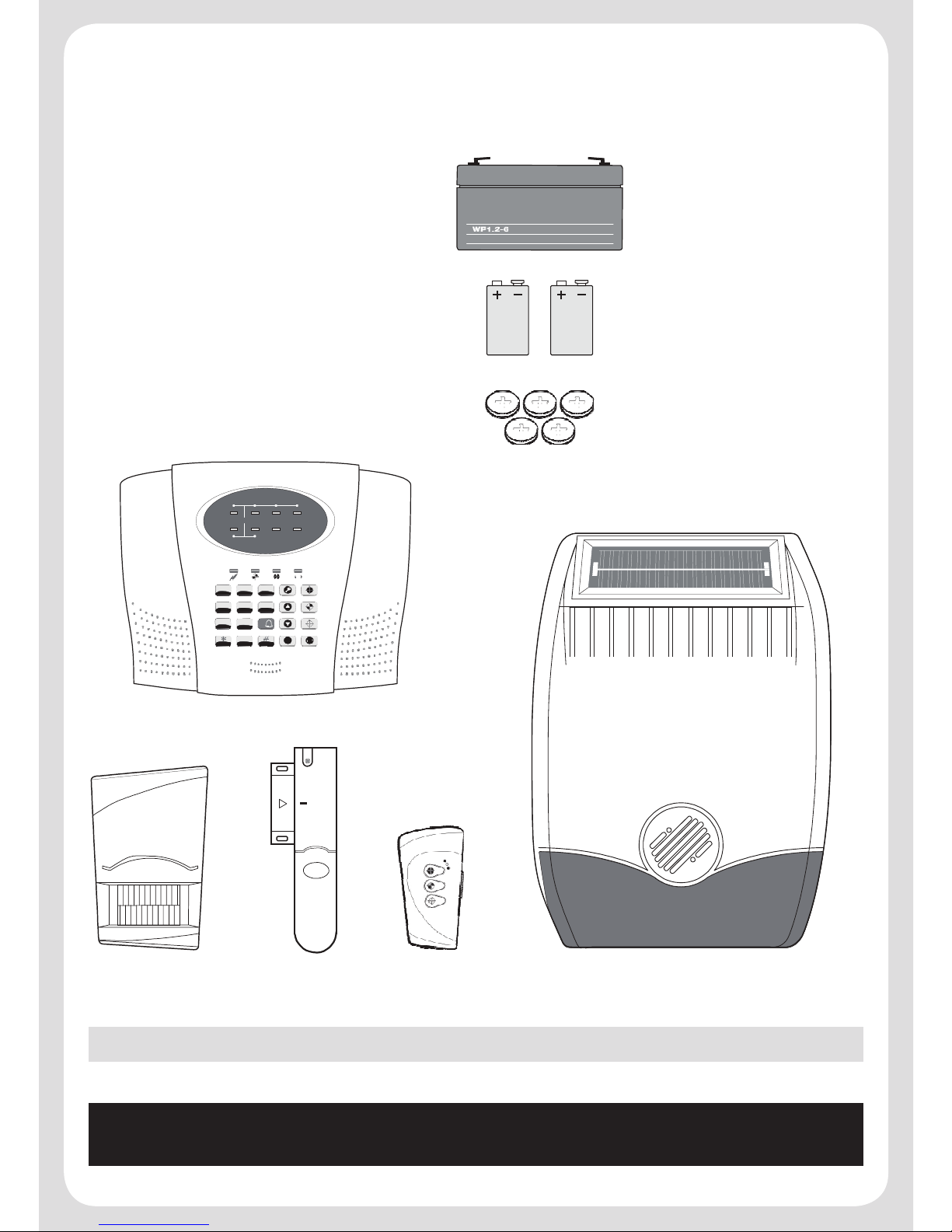
Tamper Protection
All system devices (except Remote Control Units) incorporate Tamper protection features to protect
against unauthorized attempts to interfere with the device. Any attempt to remove the battery cover
from any device (except a Remote Control) or to remove the Solar Siren or Control Panel from the
wall will initiate an alarm condition even if the system is Disarmed (unless the system is in Test or
Programming modes).
Voice Dialler
This system incorporates a telephone voice dialler which is used to call for help and / or notify the
user that the system has been triggered and an alarm has occurred.
If the Voice Dialler is enabled and an alarm condition occurs, the system will call for help using your
pre- recorded alarm message and up to four telephone numbers. When the telephone voice dialler
is activated it will call the first enabled number in the dialling sequence and play the recorded alarm
messages for the set ‘Play Time’. The recipient can acknowledge the message by pressing the
button on their telephone keypad. If the call is unanswered or an acknowledgement signal is not
received then the next number in the dialling sequence will be called. The dialler will continue calling
each number in turn until either all numbers in the sequence have been dialled the set number of
times or the dialling sequence is cancelled by an acknowledged signal from the recipient.
Jamming Detection
In order to detect any attempts to illegally jam the radio channel used by your alarm system, a
special jamming detection function is incorporated into the Control Panel and also on some Solar
Siren models. If this feature is enabled, and the radio channel is jammed continuously for 30
seconds, when the system is armed, the Solar Siren will emit a pre-alarm series of rapid bleeps for
5 seconds. If the jamming continues for a further 10 seconds or more a full alarm condition will occur.
In addition if the system is jammed for more than three periods of 10 seconds in a 5 minute interval,
this will also generate a Full Alarm condition. The jamming detection features in the Control Panel
and Solar Siren operate independently.
The Jamming Detection circuit is designed to permanently scan for jamming signals. However, it is
possible that it may detect other local radio interference operating legally or illegally on the same
frequency. If you are planning to operate the Jamming Detection feature we recommend that you
wait at least 30 days before activating this feature, this will allow time for you to become familiar with
the operation of your system.
Battery Monitoring
All devices powered by non-rechargeable batteries incorporate a battery level monitoring feature
which warns when the battery status is low.
In addition the Control Panel will also indicate a low battery status on any PIR Detector or Magnetic

6
Contact Detector on the System.
Batteries on any device indicating a low battery status must be replaced immediately.
System House Code
In order to prevent any unauthorized attempt to operate or disarm your system, you must set your
system to accept radio signals only from your own devices. This is done by setting a series of eight
miniature (DIP) switches in all devices (except the Control Panel) to the same ON / OFF combination
(the House Code) selected by the user/installer. The Control Panel is then programmed to operate
only with devices set to this House Code.
All Detectors and Remote Control Unit(s) must be set with the same House Code in order for the
system to operate correctly.
Inside the Siren, Detectors and Remote Control Unit is a series of 8 DIP switches.
The House Code is set by moving each of the 8 switches in each device to the same randomly
selected ON / OFF sequence. When setting the DIP switches, ensure that each switch ‘clicks’ fully
into position. Use the tip of a ballpoint pen or a small screwdriver to move each switch in turn.
Note: It is recommended that the system House Code is always reset to a code other than the
factory default.

7
Planning and Extending your Wire Free Alarm System
The example below shows a typical property incorporating the suggested positions for the Control
Panel, PIR and Magnetic Detectors for optimum security. Use this as a guide for your installation
in conjunction with the recommendations contained in this manual for planning your intruder alarm
system.
External
Solar Siren Magnetic Contact
Detector
PIR Movement
Detector
PIR Movement
Detector
Remote
Control
1 2 3 4
ZONE
5 6
FIRE TAMPER
1
2 3
4 5 6
7 8 9
0
ESC
LED
Control
Panel Magnetic
Contact
Detector
SHED
Back Door
KITCHEN
HALL
DINING
ROOM
PIR
Movement
Detector
PIR
Movement
Detector
LOUNGE
GROUND FLOOR GARAGE
PIR Movement
Detector
Before attempting to install your Alarm System it is important to study your security requirements
and plan your installation. The alarm system may be extended at any time to provide even greater
protection by fitting additional devices to meet your personal security needs.

8
Control Panel
!
2
!
3
!!
4
!!
5
!
6
!!
7
!!
8
!
9
!
:
!
! !
!
1
!! !
!
FTD
!
Zone LEDs
2! 3! 4! 5
!
[POF
!
6! 7
!
GJSF! UBNQFS
!
Status LEDs
Keypad
Positioning the Control Panel
When choosing a suitable location for the Control Panel, the following points should be considered.
1. The Control Panel should be located in a position out of sight of potential intruders and in a safe
location, but easily accessible for system operation.
2. The Control Panel should be mounted on a sound flat surface to ensure that the rear tamper
switch on the Control Panel is closed when the Panel is mounted. The Control Panel should be
mounted at a convenient height of between 1.5 and 2m and in a position where it will be seen
each day.
Note: If small children are in the household, a further consideration should be given to keeping
the units out of their reach.
3. It is recommended that the Control Panel should be positioned such that the Exit/Entry tone
(emitted by the Control Panel) can be heard from outside the property.
4. The Control Panel should be mounted within a protected area so that any intruder cannot reach
the Control Panel without opening a protected door or passing through an area protected by a PIR
Detector when the system is armed.
5. The Control Panel must be located within reach of a mains socket.
6. If the telephone voice dialler is to be used then the Control Panel will need connecting to a
convenient telephone point.
7. Do not locate the Control Unit closer than 1m to any large metallic object, (e.g. mirrors, radiators,
etc) as this may affect the radio range of the Control Panel.
Installing the Control Panel
1. Undo the two captive fixing screws on top of the panel and open the cover. The cover is hinged
along the bottom edge.
2. Unclip and remove the two back-up batteries on either side of the panel.

9
3. Hold the Control Panel in position on the wall and mark the positions of the four fixing holes.
Remove the Panel and drill four 5mm holes and fit the 25mm Wall Plugs.
Note: The wall plugs supplied with the product are not suitable for plasterboard walls, if mounting
the Control Panel onto plasterboard use proprietary wall plugs.
Important: Do not drill the fixing holes with the Control Panel in position; as the resulting dust and
vibration may damage the Control Panel’s internal components and invalidate the guarantee.
External Tamper Switch
Jumper Link P51
Power Supply
Cable Route
Upper
Keyhole
Fixing Hole
-Terminal
(Blue Lead)
+ Terminal
(Red Lead)
Lower
Fixing
Hole
Upper
Keyhole
Fixing Hole
+ Terminal
(Blue Lead)
-Terminal
(Black Lead)
Reset
Jumper
Link P1
Power
Supply
Jack
Socket
Inside view of Control Panel
4. Fit two 18mm No. 4 screws into the top holes until almost fully home and hang the Control Panel
over the screws using the two keyhole slots in the top corners of the panel casing.
5. Route the cable from the Power Supply Unit up behind and on the right hand side of the Control
Panel and connect the plug to the DC power socket in the panel. Ensuring that the cable is not
trapped between the Control Panel and the wall.
6. Fix the Control Panel to the wall using two 18mm No. 4 screws in the lower two fixing holes in
the Control Panel and tighten the upper fixing screws until they just grip the casing. Do not over
tighten the fixing screws or this may damage the casing.
7. Ensure that the ‘Reset’ and the ‘Hard-Wired Siren tamper detect’ jumper links are set in the OFF
position.

10
8. Connect battery leads to both back-up batteries and refit batteries.
Battery 1 (left): Red lead to + battery terminal
Blue lead to – battery terminal
Battery 2 (right): Blue lead to + battery terminal
Black lead to – battery terminal
Important: Take care when connecting battery leads to the batteries as connecting incorrectly
could damage the batteries or the Control Panel.
Note: The Power LED may flash to indicate that the unit is being operated from the back-up
batteries and that mains supply is not present.
9. Close the lid of the Control Panel and tighten the captive fixing screws.
10.Plug in and switch ON the Power Supply Unit, (the Power LED should illuminate).
11.If required, connect the Control Panel to the telephone line using the cable supplied by inserting
small RJ11 plug into socket marked LINE located on the bottom edge of the Control Panel.
Connect the BT plug on the other end of the lead to an appropriate telephone outlet.
If the cable supplied is not long enough to reach a suitable phone point then it will need extending
using a coupler and extension lead (not supplied).
Note: If the Panel Tamper alarm sounds during the installation reset the alarm by pressing:
,
1
2 3 4 ,
on the Control Panel Keypad.
Setting the Control Panel House Code
With the unit in Standby mode (Power LED only illuminated).
1. Press
,
1
2 3 4 ,
. The Control Panel will beep twice and the Arm and
Part-Arm LEDs will illuminate. All Zone, Fire and Tamper LEDS will flash.
This puts the Control Panel into programming mode.
2. Press
,
1
2 3 4 ,
. The Zone LEDs 1-6, Fire and Tamper LEDs will illuminate to indicate the
current House Code setting with an illuminated LED indicating a setting of ‘ON’ and LEDs not
illuminated indicating a setting of ‘OFF’. For example, a house code of ‘ON’, ‘ON’, ‘ON’, ‘ON’,
‘OFF’, ‘OFF’, ‘ON’, ‘OFF’ will be indicated with zone LEDs 1- 4 illuminated, Zones 5 & 6 ‘not
illuminated’, Fire Zone ‘illuminated’ and Tamper Zone ‘not illuminated’.
3. The system House Code can be set either directly at the Control Panel or via a Remote Control
Unit.
At the Control Panel:
a) By pressing buttons 1-8 on the Control Panel, setting the status LEDs so that they indicate the
required house code setting. The LEDs will switch to the opposite state each time the button
is pressed.

11
LED ON = 1, (House Code DIP Switch On)
LED OFF = 0, (House Code DIP Switch Off)
b) Press
,
1
2 3 4 ,
to save the new setting and return to programming mode.
c) Press
ESC!
to return to programming mode without saving.
Using a Remote Control Unit:
a) With the required House Code already set on the remote control, press the button on the
Remote Control.
The Control Panel will beep twice to acknowledge the signal.
The Zone, Fire and Tamper LED status will be updated to correspond with the House Code set
on the Remote Control and now programmed into the Control Panel.
b) Press
,
1
2 3 4 ,
to return to programming mode.
4. Press
ESC!
to exit programming mode and return to Standby.
5. Press
,
1
2 3 4 ,
. The Control Panel will beep and the Arm and Part-
Arm LEDs will flash.
This puts the Control Panel into test mode.
Remote Control Unit
The Remote Control Unit is used to Arm, Part-Arm and Disarm the system.
The Remote Control Unit also incorporates a Panic
switch. Activating the Panic switch on the side of
the Remote Control will immediately initiate a Full
Alarm condition whether the system is Armed or
Disarmed. The alarm can be cancelled by pressing
the ‘DISARM’ button on the Remote Control or via
the Control Panel.
Any number of Remote Control Units can be used
with your system, providing they are all coded with
the same system House Code.
The Remote Control uses a CR2032 type Lithium cell which under normal conditions will have a
typical life in excess of 1 year. Under normal battery conditions the LED on the Remote control
will illuminate only when a button is pressed. However, under low- battery conditions this LED will
flash every time the button is pressed. When this occurs the battery should be replaced as soon as
possible.
Transmit LED
Arm
Part-Arm
Disarm
Slide up
to operate
Personal Attack

12
Setting the Remote Control
1. Remove the front cover by undoing the small screw on the rear of the Remote Control.
2. Located above the battery is a row of 8 DIP switches.
Select and record a random combination of ‘ON’ and
‘OFF’ positions for the DIP switches. This will be the
system House Code that enables all elements of your
transmitters to communicate with the Control Panel.
Important: The House Code for your system should
be changed from the factory default setting.
3. Ensure that the jumper link located immediately below
the House Code DIP switches is fitted in position for
use with this alarm system.
4.
Insert the battery under the clip ensuring that the +v terminal faces upwards away from the PCB.
5. Replace the front cover and fixing screw.
Passive Infrared (PIR) Movement Detectors
PIR Detectors are designed to detect movement in a protected area by detecting changes in infra-
red radiation levels caused, for example, when a person moves within or across the devices field
of vision.
If movement is detected an alarm signal will be generated, (if the system and alarm zone is armed).
Note: PIR Detectors will also detect animals, so ensure that pets are not permitted access to areas
fitted with Passive Infra Red Detectors when the system is armed.
Any number of PIR Detectors can be used with your system, providing they are all coded with the
system House Code and are mounted within effective radio range of the Control Panel.
The PIR Detector is powered by a PP3 Alkaline battery
which under normal conditions will have an expected life
in excess of 1 year. When the battery level drops, with the
PIR Detector in normal operation mode and the battery
cover fitted, the LED behind the detection window will
flash. When this condition occurs, the battery should be
replaced as soon as possible.
Choosing a position for the PIR
Detector
The recommended position for a PIR Detector is in the
corner of a room mounted at a height between 2 and 2.5m.
At this height, the PIR Detector will have a maximum range
of up to 12m with a field of view of 110°.
House Code
Dip Switches
Jumper Link
Battery Clip
Battery
12
10
Top View
8
6
4
2 2
0 110° 0
12 10 8 6 4 2 0 2
meters
Side View
4
6
8
10
12
meters
More Sensitive
Less Sensitive

13
The Position of the PCB inside the PIR Detector can be set to 5 different positions to adjust the range
of the detection pattern created by the PIR Detector. Setting the PCB in position 3 will reduce the
range to approximately 9m, with position 1 providing a range of approximately 6m. The recommended
position setting for the PCB is in position 5.
When considering and deciding upon the mounting position for the PIR Detector the following points
should be considered to ensure trouble free operation:
1. Do not locate the PIR Detector facing a window or where it is exposed to or facing direct sunlight.
PIR Detectors are not suitable for use in conservatories.
2. Do not locate the PIR Detector where it is exposed to ventilators.
3. Do not locate the Detector directly above a heat source, (e.g. fire, radiator, boiler, etc).
4. Where possible, mount the PIR Detector in the corner of the room so that the logical path of an
intruder would cut across the fan detection pattern. PIR Detectors respond more effectively to
movement across the device than to movement directly towards it.
5. Do not locate the PIR Detector in a position where it is subject to excessive vibration.
6. Ensure that the position selected for the PIR Detector is within effective range of the Control
Panel. It is recommended that prior to installation the Detector is set and tested with the
Control Panel in Walk Test mode to ensure that they are within effective range.
Note: When the system is Armed, pets should not be allowed into an area protected by a PIR
Detector as their movement would trigger the PIR Detector and trigger an alarm.
Note: DO NOT fix the PIR Detector to metalwork or locate the unit within 1m of metalwork (i.e.
radiators, water pipes, etc) as this could affect the radio range of the Device.
Installing and configuring the PIR Movement Detectors
Ensure that the Control Panel is in Test mode.
1. Undo and remove the fixing screw from the bottom edge of the PIR Detector. Carefully pull
the bottom edge of the Detector away from the rear cover and then slide down to release the top
clips.
2. Carefully drill out the required mounting holes in the
rear cover using a 3mm drill according to whether the
unit is being mounted in a corner or against a flat wall.
3. Using the rear cover as a template, mark the positions
of the fixing holes on the wall.
4. Fix the rear cover to the wall using the two 18mm No.
4 screws and 25mm wall plugs, (a 5mm hole will be
required for the wall plugs). Do not over- tighten the
fixing screws as this may distort or damage the cover.
Mounting Hole
Positions
Rear Cover
Fixing Screw

14
Note: The wall plugs supplied with the product are not suitable for plasterboard walls, if mounting
the PIR Detector onto plasterboard use proprietary wall plugs.
5. Set the House Code for the PIR Detector by setting DIP switches 1-8 of SW2 to the same ON/
OFF combination as the House Code DIP switches in all other system devices.
6. Set the alarm zone which the Detector will operate on by setting DIP switches 1-3 of SW3 as
follows:
DIP 1 DIP 2 DIP 3
Zone 1 OFF OFF OFF
Zone 2 OFF OFF ON
Zone 3 OFF ON OFF
Zone 4 OFF ON ON
Zone 5 ON OFF OFF
Zone 6 ON OFF ON
7. DIP4 of SW3 is used to set the PIR Detector for walk test mode, which allows the operation of the
Detector to be checked during installation without triggering a Full Alarm.
ON Walk Test mode
OFF Normal operation
Note: On initial installation the PIR Detector should be set into Walk Test mode ready for testing.
8. The PIR Detector incorporates a sensitivity feature designed to compensate for situations where
the Detector may be affected by environmental changes, (e.g. insects, air temperature, etc). This
feature is called “Detection Sensitivity” and may be set to Standard or High Sensitivity.
Note: The higher the sensitivity the less movement will be necessary before the PIR Detector
will trigger the alarm.
The recommended setting is Standard Sensitivity. If set to High Sensitivity, in some cases,
extreme environmental problems could cause unexplained false alarms. If this is experienced it
may be necessary to reset the PIR Detector to Standard Sensitivity.
Set the required detection sensitivity using DIP 5 of SW3 as follows:
OFF Standard Sensitivity
ON High Sensitivity
9. Connect the PP3 Alkaline battery to the battery clip.
Note: When the 9V Alkaline battery is connected the LED behind the lens will rapidly flash for
approximately 2-3 minutes until the PIR Detector has warmed up and stabilized. The LED will
then stop flashing and turn OFF.
10.Check that the PIR Detector PCB is located and set in the correct position to give the detection
zone pattern required.

15
To adjust the PCB position, simply slide it up or
down ensuring that the location legs are aligned
with the required position number marked on the
board.
11.Refit the PIR Detector to the rear cover by offering
the PIR Detector up to the rear cover and locate
the clips in the top edge into the rear cover. Push
the lower edge of the PIR Detector into place and
refit the fixing screw in the bottom edge of the PIR
Detector to secure in position. Do not over-tighten
the fixing screws as this may damage the casing.
Testing the PIR Detectors
Ensure that the system is in Test mode.
Ensure that the PIR Detector is set in Walk Test mode (i.e. DIP 4 of SW3 ON) and mounted in
position on the wall. Allow 2-3 minutes for the PIR Detector to stabilize before commencing testing.
1. Put the Control Panel into “Walk Test” mode by pressing
,
1
2 3 4 ,
on the Control Panel.
The Panel will beep and the Zone 1 LED will illuminate.
2. Walk into and move slowly around the protected area, each time the PIR Detector senses
movement the LED behind the lens will flash. In addition, the Control Panel will beep twice
to indicate that the alarm signal has been received and the appropriate zone LED which the
Detector is set for will illuminate.
Note: In normal operation, the LED will not flash on movement detection. If necessary re-adjust
the detection pattern by changing the mounting position of the PCB within the PIR Detector
housing.
3. Reset the PIR Detector into Normal operation mode by switching DIP 4 of SW3 to the OFF
position and refit in position.
4. Press
ESC!
on the Control Panel to exit Walk Test mode.
Note: When the PIR Detector is fully installed, i.e. battery cover is refitted; the unit will not
detect movement for approximately 45 seconds after each activation. (This feature is present to
conserve battery power and maximize the battery life).
5
4
PCB Positions
3
Indicator
2
(positions 1-5)
1
PCB Position
Range
1
6m
3
9m
5
12m

16
Magnetic Contact Detectors
Installing and setting the Magnetic Contact Detectors
Ensure that the system is in Test mode.
1. Remove the battery cover by sliding and lifting it off. (DO NOT use a screwdriver to lever off).
2. Remove the battery holder by carefully tilting up the end and pulling the connector off the printed
circuit board.
3. Mount the Magnetic Contact Detector to the fixed part of the frame along the opening edge
opposite the hinges using either the double sided adhesive tape or screws provided.
When fixing the Magnetic Contact Detector with screws, the top of the Detector is secured with
a keyhole slot over the screw head of the smaller pan head screw. The bottom is secured using
the 12mm countersunk head screw fitted within the battery compartment. Carefully drill out the
centre of the fixing screw hole in the battery compartment using a 3mm drill. Do not over-tighten
the fixing screws as this may distort or damage the casing.
4. Fit the Magnet to the moving part of the
door/ window opposite the Magnetic Contact
Detector using the two 15mm fixing screws.
Ensuring that the parallel gap between the
Magnet and Detector is less than 10mm
and that the arrow on the Magnet is pointing
towards and aligned with the mark on the top
section of the Detector.
5. If an additional wired Magnetic Contact
Detector is required, this should be wired
to the terminal block provided in the battery
compartment. The wired contact should be
connected using two core (24AWG) wire of
maximum length 1.5m.
Important: If an additional wired contact is not connected, then the jumper link SW2 must be
fitted for the Magnetic Contact Detector to operate correctly.

17
6. Set the House Code for the Magnetic Contact Detector by setting DIP switches 1-8 to the same
ON/OFF combination as the House Code DIP switches in all other system devices.
7. Set the alarm zone which the Detector will operate on with DIP switches 9-11 as follows:
DIP 9 DIP 10 DIP 11
Zone 1 OFF OFF OFF
Zone 2 OFF OFF ON
Zone 3 OFF ON OFF
Zone 4 OFF ON ON
Zone 5 ON OFF OFF
Zone 6 ON OFF ON
8. Slide the two batteries supplied into the battery holder, ensuring that the positive (+) side is
uppermost on each battery as it is installed.
9. Carefully refit the battery holder onto the Detector ensuring that the spring connectors slide onto
either side of the circuit board.
10.Fit the battery cover into position on the Magnetic Contact Detector.
Testing the Magnetic Contact Detectors
Ensure that the system is in Test mode.
1. Put the Control Panel into “Walk Test” mode by pressing
,
1
2 3 4 ,
on the Control Panel.
The Panel will beep and the Zone 1 LED will illuminate.
2. Remove the battery cover from the Magnetic Contact Detector.
The LED on the Detector will illuminate for approx. 1 second as the battery cover is removed and
the tamper switch is activated. In addition, the Control Panel will beep twice to indicate that the
alarm signal has been received and the Tamper LED will illuminate.

18
3. Open the door/window to remove the magnet from the Detector.
As the magnet is moved away from the Detector the LED will illuminate for approximately 1
second to indicate that the Detector has been triggered. In addition, the Control Panel will beep
twice to indicate that the alarm signal has been received and the appropriate zone LED, which
the Detector is set for, will illuminate.
4. If any external Magnetic Contact Detectors are connected to the Detector, operate these one at
a time. Each time a contact is opened the LED on the Detector should illuminate for 1 second to
indicate that it has been triggered.
5. Replace the battery cover on the Detector. Press
ESC!
on the Control Panel to exit Walk Test.
External Solar Siren
The Siren and Solar Panel are all encapsulated within a tough polycarbonate housing. This housing
provides full protection against adverse weather conditions.
An LED/Strobe unit is built into the siren to act as a visible deterrent/indication that the system is
active. The Strobe LEDs will slowly and alternately flash whether the system is armed or disarmed.
However, during an alarm condition the Strobe LEDs will flash rapidly.
An integral anti-tamper switch provides additional security protection to the Solar Siren and will
immediately generate a full alarm should any unauthorized attempt be made to interfere with
and remove the Solar Siren cover.
The Solar Siren is powered by a high capacity battery. A Solar Panel mounted on the top of the
housing charges the battery during daylight hours. During darkness, only a small amount of energy
is required to operate the Solar Siren unit.
An Alkaline 9V PP3 battery is supplied in the Solar Siren to boost the initial power to the unit when
the system is first activated until the Solar Panel charges the main battery.
Positioning the Solar Siren
The Solar Siren should be located in a prominent position
so that it can be easily seen and heard. The Solar Siren
should be mounted on a sound flat surface so that the rear
tamper switch is not activated when mounted. Ensure that
the tamper switch does not fall into the recess between
brick courses as this could prevent the switch from closing
and give a permanent tamper signal.
Although the Solar Siren is designed to work on any
aspect wall, for optimum performance you should refrain
from mounting the unit on a north facing wall, where
possible.
Shadows cast by neighbouring walls, trees and roof
overhangs should also be avoided. If the Solar Siren is to
be mounted below the eaves, it should be positioned a
distance of at least twice the width of the eaves overhang below the eaves. Remember that in winter
the sun is lower in the sky and you should avoid winter shadows where possible.

19
The Solar Siren contains a sophisticated radio receiver. However, reception of radio signals can
be affected by the presence of metallic objects within the vicinity of the Solar Siren. It is therefore
important to mount the Solar Siren a minimum distance of 1m away from any external or internal
metalwork, (i.e. drainpipes, gutters, radiators, appliances etc).
Ensure that the position selected for the Solar Siren is within effective range of the Control Panel,
(refer to “Testing the Control Panel & Remote Control”).
Installing the Solar Siren
1. Remove the fixing screw from the bottom edge of the Solar Siren Siren housing and carefully
hinge off the front cover. All electronic components are housed within the front cover:
9
8
7
6
5
4
3
2
1
NO
Solar Panel
Front Cover
Locating Tabs
Tamper
Switch
Receiver
Aerial
DIP Switch
Cover
7.5 Volt DC
Charging Adaptor
Input
6 Volt 1.2Ahr
Rechargeable
Battery
Beep Disable Link
P2
P3 Siren Disable Link
P1 Jamming
Detection Link
9 Volt PP3
Initial Power-Up
Battery
Main Configuration
Switch (in SIREN
Position)
C.U.
SIREN
Printed Circuit
Board Enclosure
House Code
DIP Switches 1-8
Alarm Duration
DIP Switch 9
C.U.
SIREN
Siren
LED/Strobe PCB
Inside view of Solar Siren
2. Hold the mounting plate in position and mark the positions of the four mounting holes (a spirit level
placed on the casing will ensure a perfect level). Drill four 6mm holes and fit the wall plugs.
3. Fit the two 30mm fixing screws in the top holes leaving approx. 10mm of the screw protruding.
4. Fit the top keyhole slots of the mounting plate over the screw heads. Adjust the mounting plate
and adjust the screws until they form a neat fit with the mounting plate with minimal movement
5.
Secure the mounting plate in position using the two 25mm fixing screws in the bottom fixing holes.
6. Ensure that the Siren’s main configuration switch on the LED Indicator board is set to “Siren”.

20
Setting the Solar Siren
Ensure that the Solar Siren main configuration switch if fitted on the LED strobe board is set to
“SIREN” for use with this alarm system.
Undo the 3 screws holding the DIP Switch cover in place and remove the cover.
House Code
Under the corner cover you will find a series of 9 DIP
switches. DIP switches 1- 8 are used to set the House Code
for the siren and must be set to the same ON/OFF
combination as all other system devices.
Note: When the Solar Siren is viewed as shown above
(Solar panel at top) the DIP switches are ‘upside down’.
Alarm Duration Limit
If required the maximum length of time that the External Solar Siren will sound for when activated
under an alarm condition may be limited to 3 minutes using DIP switch 9 as follows:
OFF 3 minute limit
ON 10 minutes or same as programmed setting on Control Panel.
Beep Disable
The Solar Siren will acknowledge Disarm signals from the Remote Control by beeping twice. It is
possible to disable the beeps if required by removing the jumper link P2 on the circuit board.
Siren Disable
If for any reason you need to disable the Siren, remove jumper link P3 on the circuit board. This
will prevent the Siren from sounding during an alarm condition. However, the Siren will still beep to
acknowledge signals from the Remote Control, (provided the beep feature is not disabled).
Once you have completed configuring the Solar Siren, refit the DIP switch cover and replace the
three cover fixing screws. Do not over tighten the screw as this could damage the thread.
Initial Power-Up of the Solar Siren
1. Connect the 9V PP3 initial power battery to the battery clip.
Connect the rechargeable battery to the charging leads. Connect the Red lead to the Red (+)
terminal and the Black lead to the Black (-) terminals.
Note: Once the batteries have been connected, the Siren will be operational and it is important
that the Solar panel receives sufficient light to maintain the battery charge. The Siren should not
be operated repeatedly during installation and testing, as this will rapidly drain the battery. It is
recommended that the Siren be left for at least a day in order to charge the battery before the
system is armed.
Alarm Duration DIP switch 9
ON
1 2 3 4 5 6 7 8 9
House Code
(Always change from the factory setting)
This manual suits for next models
1
Table of contents
Other LuxHome Security System manuals