Climax Technology SRAC-23-ZBS User manual
1
SRAC-23-ZBS / SRAC-23B-ZBS / SRAC-23B-ZBSR
AC Powered Indoor Siren
Introduction
SRAC-23(B)-ZBS is an AC Powered ZigBee Indoor Siren. It is capable of raising alarm upon receiving
alarm signal from the coordinator in the ZigBee network when an alarm is activated. During the alarm,
the siren will sound alarm with its built-in buzzer.
The Indoor Siren utilizes ZigBee technology for wireless signal transmission. ZigBee is a wireless
communication protocol that is reliable and has low power consumption and high transmission efficiency.
Based on IEEE802.15.4 standard, ZigBee allows a large amount of devices to be included in a network
and coordinated for data exchange and signal transmission.
l
Model
The Indoor Siren includes the following models:
SRAC-23-ZBS: Standard Indoor Siren
SRAC-23B-ZBS: Features built-in rechargeable battery to serve as backup power source when the Siren
is unplugged from AC power.
SRAC-23B-ZBSR: Features built-in rechargeable battery and ZigBee network router function
Model No.
Rechargeable Battery
ZigBee Router
SRAC-23-ZBS
No
No
SRAC-23B-ZBS
Yes
No
SRAC-23B-ZBSR
Yes
Yes
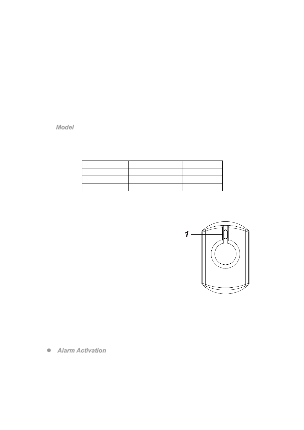
Parts Identification
1. Function Button/LED Indicator
Function Button Usage:
- Press once to send a supervision signal.
- Press and hold the button for 10 seconds then release to
reset the Indoor Siren.
- Press and hold the button for 3 seconds to change
indication beep volume.
LED Indicator:
- One Flash:
The security system is armed.
- Two flashes:
The security system is disarmed
The Indoor Siren has successfully joined a ZigBee
network
- One Flash every 20 minutes (SRAC-23(B)-ZBS Only)
The Indoor Siren has not joined any ZigBee network, or has lost
connection to its current ZigBee network.
- Continuous Flash:
The Siren is alarming.
Features
l
Alarm Activation
When an alarm is activated, the Indoor Siren will activate its buzzer and the LED indicator will flash
continuously while the siren is alarming. If the alarm system control panel has programmed alarm
duration, the Siren will be activated according to panel alarm length. If the alarm system does not
have alarm duration programmed, the Siren will be activated for 15 minutes.
2
l
Audio Status Indication
l The Indoor Siren activates different audio sounds
according to different statuses of the security system, as
listed in table on the right:
l You can change t he volume of the i ndication beeping
sound between High and Low by pressing and holding the
learn button for 3 seconds. The factory default volume is
set to Low.
l
Power Supply
The Siren is powered by AC power; plug the Siren into the power socket to activate the Siren. The
Siren will enter normal operation mode.
SRAC-23B-ZBS and SRAC-23B-ZBSR models have a rechargeable battery inside that serves as
backup when the Siren is unplugged from AC power. The battery will be charged automatically
when the Siren is plugged. It takes about 72 hours to fully charge the battery.
l
Low Battery Detection (SRAC-23B-ZBS / SRAC-23B-ZBSR only)
After AC power failure, the Siren will transmit a Low Battery signal to The Control Panel when low
battery voltage is detected. To restore battery, re-plug AC power into the power socket. After 12
hours, the Siren will transmit a low battery restored notification to the Control Panel.
l
AC Failure Detection
Whenever the Siren is removed from the power socket, the siren will transmit an AC fault signal to
the coordinator to notify the situation and switch to its internal battery for power supply.
When the Siren is plugged in again on the power socket, it will send an AC power restore signal to
the coordinator.
l
Supervision
The Indoor Siren will transmit a supervision signal to report its condition regularly according to user
setting. The factory default interval is 30 minutes. The user can also press the Function Button once
to transmit a supervision signal manually.
ZigBee Network Setup
l
ZigBee Device Guideline
ZigBee is a wireless communication protocol that is reliable and has low power consumption and
high transmission efficiency. Based on IEEE802.15.4 standard, ZigBee allows a large amount of
devices to be included in a network and coordinated for data exchange and signal transmission.
Due to the fundamental structure of ZigBee network, ZigBee device will actively seek and join
network after powering on. Since performing a task in connecting network may consume some
power, it is required to follow the instructions to avoid draining battery of a ZigBee device
- Ensure your ZigBee network router or coordinator is powered on before powering on the ZigBee
device.
- Ensure the ZigBee network router or coordinator is powered on and within range while a ZigBee
device is in use.
- Do not remove a ZigBee device from the ZigBee network router or coordinator without powering
down the ZigBee device.
Joining the ZigBee Network
As a ZigBee device, the Indoor Siren needs to join a ZigBee network to send and receive alarm
signal. Please follow the steps below to join the Indoor Siren into the ZigBee network.
1. Plug the Indoor Siren into a power outlet.
2. Press and hold the function button for 10 seconds as the Siren resets and starts searching for
existing ZigBee network. Please make sure the permit-to-join feature on the router or coordinator
of your ZigBee network is enabled.
3. If the Siren successfully joins a ZigBee network, the LED Indicator will flash twice to confirm.
4. After joining the ZigBee network, the Indoor Siren will be registered in the security system in the
network automatically. Please check the security system control panel or CIE (Control and
Indicating Equipment) to confirm if joining and registration is successful.
5. For SRAC-23(B)-ZBS, after joining the ZigBee network, if the Siren loses connection to its
current ZigBee network, the LED indicator will flash every 20 minutes to indicate. Please check
your ZigBee network condition and siren signal range and correct the condition.
Siren Audio
Arm/Home
1 beep
Disarm
2 beeps
Entry/Exit Sound
Count-down
beeps

3
l
Removing Device from ZigBee Network (Factory Reset)
To r emov e t he Sire n f rom c urre n t Z i gBee netw o rk, t h e S i ren mus t b e p ut t o F a ctor y Rese t to
complete device removal. Factory Reset function will clear the device of its stored setting
information and prompt the Siren to search for new ZigBee network.
Before removing device, make sure the Siren is within current ZigBee network signal range
1. Press and hold the function button for 10 seconds, then release the button to reset Siren.
2. Upon reset, the Siren will clear current ZigBee network setting and transmit signal to ZigBee
coordinator to remove itself from current ZigBee network. It will then actively search for
available ZigBee network again and join the network automatically.
l
ZigBee Router Device Capacity (SRAC-23B-ZBSR)
The Siren model with Router function (SRAC-23B-ZBSR) allows other ZigBee devices to join the
ZigBee Network through the Router. It has maximum capacity of 40 ZigBee devices or routers
Appendix (For developers only.)
l
Indoor Siren Cluster ID
Device ID: IAS Warning Device: 0x0403
Endpoint: 0x01
Server Side
Client Side
Mandatory
Basic (0x0000)
None
Identify(0x0003)
IAS Zone(0x0500)
IAS WD(0x0502)
Optional
None
None
l
Attribute of Basic Cluster Information
Identifier
Name
Type
Range
Access
Default
Mandatory
/ Optional
0x0000
ZCLVersion
Unsigned
8-bit integer
0x00 – 0xff
Read
only
0x01
M
0x0001
ApplicationVersion
Unsigned
8-bit integer
0x00 – 0xff
Read
only
0x00
O
0x0003
HWVersion
Unsigned
8-bit integer
0x00 –0xff
Read
only
0
O
0x0004
ManufacturerName
Character
String
0 – 32 bytes
Read
only
Climax
Techn ology
O
0x0005
ModelIdentifier
Character
String
0 – 32 bytes
Read
only
(Model Version)
O
0x0006
DateCode
Character
String
0 – 16 bytes
Read
only
O
0x0007
PowerSource
8-bit
0x00 –0xff
Read
only
M
0x0010
LocationDescription
Character
String
0 – 32 bytes
Read /
Write
O
0x0011
PhysicalEnvironment
8-bit
0x00 –0xff
Read /
Write
0x00
O
0x0012
DeviceEnabled
Boolean
0x00 –0x01
Read /
Write
0x01
M
l
Attribute of Identify Cluster Information
Identifier
Name
Type
Range
Access
Default
Mandatory
/ Optional
0x0000
IdentifyTime
Unsigned
16-bit integer
0x00 –0xffff
Read /
Write
0x0000
M
l
Attribute of IAS Zone Cluster Information
Identifier
Name
Type
Range
Access
Default
Mandatory
/ Optional
0x0000
ZoneState
8-bit
All
Read
0x00
M

4
Enumeration
only
0x0001
ZoneType
16-bit
Enumeration
All
Read
only
M
0x0002
ZoneStatus
16-bit bitmap
All
Read
only
0x00
M
0x0010
IAS_CIE_ADDRESS
IEEE
ADDRESS
Valid 64bit
IEEE address
Read /
Write
M
0x0011
ZONE_ID
Unsigned
8-bit integer
All
Read
only
0xFF
M
l
Attribute of IAS WD Cluster Information
Identifier
Name
Type
Range
Access
Default
Mandatory
/ Optional
0x0000
MaxDuration
Unsigned
16-bit integer
0x00 –0xfffe
Read /
Write
240
M

1
KP-23EL-ZBS-ACE Remote Keypad
Introduction
KP-23EL-ZBS-ACE is a ZigBee Remote Keypad designed to provide quick access control of the ZigBee network coordinator or
system control panel. It can send wireless signals to and receive wireless signals from the coordinator in the ZigBee network.
The Keypad can either be mounted on a flat surface or wall mounted with the use of the 2 mounting knockouts. It also has
tamper protection switch which will be activated upon unauthorized removal.
The Keypad utilizes ZigBee technology for wireless signal transmission. ZigBee is a wireless communication protocol that is
reliable and has low power consumption and high transmission efficiency. Based on the IEEE802.15.4 standard, ZigBee allows a
large amount of devices to be included in a network and coordinated for data exchange and signal transmission
The Keypad serves as an end device in the ZigBee network. It can be included in the ZigBee network to transmit signal upon
activation, but cannot permit any other ZigBee device to join the network through the Keypad.
Identifying the Parts
1. Active LED (Blue)
Blue On: Keypad activated.
Blue Flash: Keypad activated under low battery condition
2. Status LED (Blue / Red)
Red On: ZigBee IAS ACE Arm All Zones command successful.
Red flash: ZigBee IAS ACE Arm Day/Home Zones Only command successful.
Blue On: ZigBee IAS ACE Disarm command successful.
Blue Flash: (4 beeps) Invalid code.
(3 beeps) Arm Fault.
3. ZigBee Network / Fault Display LED (Amber)
Amber flash once: Keypad has been reset
Amber flash twice: Keypad successfully joins ZigBee network
Amber flash: (3 beeps) Arm Fault
Amber On: Alarm in Memory
4. Away Arm Key
5. Home Arm Key
6.
!
Key
7. Disarm / ZigBee Network Key
- Press and hold for 10 seconds to reset the Keypad.
8. Battery Insulator
9. Mounting Holes
10. Tamper Swtich
Features
l
l
P
Po
ow
we
er
r
S
Sa
av
vi
in
ng
g
F
Fe
ea
at
tu
ur
re
e
l When idle, Remote keypad is in Stand-by mode and uses no power. Upon any key press, the Keypad will activate and
wake-up for 5 seconds. The Active LED will also turn on for 5 seconds.
l After 5 seconds of key inactivity, the power goes off and it returns to Stand-by mode.
l Upon completion of a command input, the power goes off and Remote keypad returns to Stand-by mode.
l
l
B
Ba
at
tt
te
er
ry
y
l The Keypad uses one EL123AP 3V Lithium battery as its power source.
l Remote keypad can also detect the battery status. If the battery voltage is low, the Active Amber LED will turn on for 5
seconds upon activation. Whenever Remote Keypad transmits a signal, the Low battery signal will be sent along to the
system.
l Before shipment, the battery is pre-installed by the factory. Pull out the Battery Insulator to start using Keypad.

2
l
l
C
Ch
ha
an
ng
gi
in
ng
g
t
th
he
e
B
Ba
at
tt
te
er
ry
y
1. Put the system into disarmed mode.
2. Loosen the cover fixing screw using a Philips screwdriver and detach the cover from the base.
3. Take out t he old batt er y a nd pres s a ny key twice to discharge before replacing the new battery in the battery
compartment. Please note the polarity of the battery when fitting in.
4. Reattach the cover to the base and tighten the cover fixing screw using a Philips screwdriver.
l
l
T
Ta
am
mp
pe
er
r
P
Pr
ro
ot
te
ec
ct
ti
io
on
n
l The tamper switch is compressed against the mounting surface when the Keypad is properly installed. When the
keypad is removed from installed location or when the cover is opened, the tamper switch will be triggered and the
Keypad will transmit a tamper open signal to the ZigBee network coordinator or system control panel.
l The Tam pe r switch will only be activated 5 minutes after joining a ZigBee network.
l If tamper protection is violated, tamper protection will only be activated again 5 minutes after the tamper is restored.
ZigBee Network Setup
l
l
Z
Zi
ig
gB
Be
ee
e
D
De
ev
vi
ic
ce
e
G
Gu
ui
id
de
el
li
in
ne
e
ZigBee is a wireless communication protocol that is reliable, has low power consumption and has high transmission
efficiency. Based on the IEEE802.15.4 standard, ZigBee allows a large amount of devices to be included in a network and
coordinated for data exchange and signal transmission.
Due to the fundamental structure of ZigBee network, ZigBee device will actively seek and join network after powering on.
Since performing a task in connecting network may consume some power, it is required to follow the instructions to avoid
draining battery of a ZigBee device
- Ensure your ZigBee network router or coordinator is powered on before inserting battery into the ZigBee device.
- Ensure the ZigBee network router or coordinator is powered on and within range while a ZigBee device is in use.
- Do not remove a ZigBee device from the ZigBee network router or coordinator without removing the battery from a ZigBee
device.
l
l
J
Jo
oi
in
ni
in
ng
g
t
th
he
e
Z
Zi
ig
gB
Be
ee
e
N
Ne
et
tw
wo
or
rk
k
As a ZigBee device, the Keypad needs to join a ZigBee network to transmit and receive signal. Please follow the steps
below to join the device into the ZigBee network.
1. Pull out the Battery Insulator to activate the battery.
2. Press and hold the Disarm key for 10 seconds, release the button when the Keypad emits 2 beeps and the ZigBee
Network LED will flash once. The Keypad will reset and scan for an existing ZigBee network. Please make sure to
enable the permit-join feature on the router or coordinator of your ZigBee network.
3. After joining the ZigBee network, the ZigBee Network LED will flash twice the Keypad will emit one long beep and it
will be registered in the security system in the network automatically. Please check the ZigBee network coordinator,
system control panel, or CIE (Control and Indicating Equipment) to confirm if joining and registration is successful.
4. The Keypad will not emit any sounds if it did not join the ZigBee network. Please check your ZigBee network
coordinator, control panel or CIE setting to ensure the permit-join function is available, and then use the Factory
Reset function below to join the ZigBee network.
l
l
R
Re
em
mo
ov
vi
in
ng
g
D
De
ev
vi
ic
ce
e
f
fr
ro
om
m
Z
Zi
ig
gB
Be
ee
e
N
Ne
et
tw
wo
or
rk
k
(
(F
Fa
ac
ct
to
or
ry
y
R
Re
es
se
et
t)
)
To rem o ve the Keypad from current ZigBee network, the Keypad must be put to Factory Reset to complete device removal.
Factory Reset function will clear the device of its stored setting information and prompt the Keypad to search for new ZigBee
network.
Before removing device, make sure the Keypad is within current ZigBee network signal range
1. Press and hold the function button for 10 seconds, then release the button to reset Keypad.
2. Upon reset, the Keypad will clear current ZigBee network setting and transmit signal to ZigBee coordinator to remove
itself from current ZigBee network. It will then actively search for available ZigBee network again and join the network
automatically.
Installation
l
l
M
Mo
ou
un
nt
ti
in
ng
g
t
th
he
e
R
Re
em
mo
ot
te
e
K
Ke
ey
yp
pa
ad
d
To mo unt t he rem ot e ke yp ad:
1. Remove the front cover by loosening the cover fixing screw using a Philips screwdriver.
2. Using the 2 mounting holes of the base as a template, mark off the positions in the most appropriate place.
3. Insert the wall plugs if fixing into plaster or brick surface.
4. Screw the base onto the wall plugs using a Philips screwdriver.
5. Replace the front cover and tighten the cover fixing screw using a Philips screwdriver.
l
l
U
Us
si
in
ng
g
R
Re
em
mo
ot
te
e
k
ke
ey
yp
pa
ad
d
w
wi
it
th
h
Z
Zi
ig
gB
Be
ee
e
R
Ro
ou
ut
te
er
r
IMPORTANT NOTE
If the Remote keypad installation location is away from your system control panel and requires ZigBee routers to improve
signal strength. DO NOT use a ZigBee Router without backup battery. A ZigBee router without battery will be powered down
during AC power failure and the Remote keypad connected to the router will lose connection with ZigBee network. You
should plan your Remote keypad installation location using only ZigBee router with backup battery.

3
Operation
The Keypad controls system by sending commands according to ZigBee IAS ACE commands.
l
l
S
Sy
ys
st
te
em
m
M
Mo
od
de
e
C
Co
on
nt
tr
ro
ol
l
l Away Arm: Enter a system PIN code and press the Arm key to arm the control panel according to ZigBee IAS
ACE Cluster command: Arm command – Arm All Zones.
If successful, the Status Red LED will light up briefly and the Keypad will emit 1 beep
l Home Arm: Enter a system PIN code press the Home Arm key to to arm the control panel according to ZigBee
IAS ACE Cluster command: Arm command – Arm Day/Home Zones Only
If successful, the Status Red LED will flash 4 times and the Keypad will emit 3 beeps
l Disarm: Enter a system PIN code and press the Disarm key to disarm the control panel according to ZigBee IAS
ACE Cluster command: Arm command – Disarm.
If successful, the Status Blue LED will light up briefly and the Keypad will emit 2 beeps.
l
l
F
Fa
au
ul
lt
t
C
Co
on
nd
di
it
ti
io
on
n
l When invalid code is entered to Arm/Disarm the system, the Blue Status LED will flash 5 times and the Keypad will emit
4 short beeps to indicate error.
l If incorrect User PIN Codes are entered for 4 times, the Keypad will disable the key input function for 1 minute. During
this time, pressing any key on the Remote Keypad will emit 1 beep but no actions will be performed.
After 1 minute, KP will emit a long beep to indicate that the key function is back to normal.
l When fault condition exists within the system while attempting to arm. Both the Blue Status and amber Fault LED will
flash 5 times, and the Keypad will emit 3 short beeps to indicate error.
l
l
D
Du
ua
al
l
K
Ke
ey
y
F
Fu
un
nc
ct
ti
io
on
ns
s
Dual Key functions are activated by pressing and holding two keys on the Keypad simutaneousy.
l 1 + 3: Activate a Panic Alarm according to ZigBee IAS ACE Cluster command: Panic command.
l 4 + 6: Activate a Fire Alarm according to ZigBee IAS ACE Cluster command: Fire command.
l 7 + 9: Transmit IAS ACE with command identifier field value of “0xff” as self-defined properitary protocol
l Ý + #: Activate an Emergency Alarm according to ZigBee IAS ACE Cluster command: Emergency command
l
l
A
Al
la
ar
rm
m
i
in
n
M
Me
em
mo
or
ry
y
l If there is Alarm in Memory when disarming the system using the Keypad, both the Blue Status LED and amber Fault
LED will turn on briefly and the Keypad will emit 5 beeps.
Appendix
(The Appendix information is for developers only.)
l
l
R
Re
em
mo
ot
te
e
K
Ke
ey
yp
pa
ad
d
C
Cl
lu
us
st
te
er
r
I
ID
D
Device ID: IAS Ancillary Control Equipment (ACE) 0x0401
Endpoint: 0x01
Server Side
Client Side
Mandatory
Basic (0x0000)
Basic (0x0000)
Identify(0x0003)
Identify(0x0003)
IAS Zone(0x0500)
IAS ACE(0x0501)
Optional
None
None
l
l
A
At
tt
tr
ri
ib
bu
ut
te
e
o
of
f
B
Ba
as
si
ic
c
C
Cl
lu
us
st
te
er
r
I
In
nf
fo
or
rm
ma
at
ti
io
on
n
Identifier
Name
Type
Range
Access
Default
Mandatory /
Optional
0x0000
ZCLVersion
Unsigned 8-bit
integer
0x00 –0xff
Read
only
0x01
M
0x0001
ApplicationVersion
Unsigned 8-bit
integer
0x00 –0xff
Read
only
0x00
O
0x0003
HWVersion
Unsigned 8-bit
integer
0x00 –0xff
Read
only
0
O
0x0004
ManufacturerName
Character String
0 – 32 bytes
Read
only
Climax
Techn ology
O
0x0005
ModelIdentifier
Character
string
0 – 32 bytes
Read
only
(Model Version)
O
0x0006
DateCode
Character String
0 – 16 bytes
Read
only
O
0x0007
PowerSource
8-bit
0x00 –0xff
Read
M

4
only
0x0010
LocationDescription
Character String
0 – 32 bytes
Read /
Write
O
0x0011
PhysicalEnvironment
8-bit
0x00 –0xff
Read /
Write
0x00
O
0x0012
DeviceEnabled
Boolean
0x00 –0x01
Read /
Write
0x01
M
l
l
A
At
tt
tr
ri
ib
bu
ut
te
e
o
of
f
I
Id
de
en
nt
ti
if
fy
y
C
Cl
lu
us
st
te
er
r
I
In
nf
fo
or
rm
ma
at
ti
io
on
n
Identifier
Name
Type
Range
Access
Default
Mandatory /
Optional
0x0003
IdentifyTime
Unsigned 16-bit
integer
0x0000 –0xffff
Read /
Write
0x0000
M
l
l
A
At
tt
tr
ri
ib
bu
ut
te
e
o
of
f
I
IA
AS
S
Z
Zo
on
ne
e
C
Cl
lu
us
st
te
er
r
I
In
nf
fo
or
rm
ma
at
ti
io
on
n
Identifier
Name
Type
Range
Access
Default
Mandatory /
Optional
0x0000
ZoneState
8-bit
Enumeration
All
Read
only
0x00
M
0x0001
ZoneType
16-bit
Enumeration
All
Read
only
M
0x0002
ZoneStatus
16-bit bitmap
All
Read
only
0x00
M
0x0010
IAS_CIE_ADDRESS
IEEE ADDRESS
Valid 64bit IEEE
address
Read /
Write
M
0x0011
ZONE_ID
Unsigned 8-bit
integer
All
Read
only
0xFF
M
This manual suits for next models
2
Table of contents
Other Climax Technology Security System manuals


