7
Remote Control Unit
The Remote Control Unit is used to Arm and Disarm the system.
The Remote will activate the Instant-Arm, Delay-
Arm or Disarm functions.
The Remote Control also incorporates a Personal
Attack Switch (PAS). Activating the PAS will
immediately initiate a Full Alarm condition whether
the system is Armed or Disarmed, (unless the
system is in Service, Test or Program mode).
Any number of Remote Controls can be used with
your system, providing they are all coded with the
same system House Code.
The Remote Control is powered by a CR2032 type Lithium Cell battery which under normal conditions
will have a typical life in excess of 1 year. Under normal battery conditions the LED on the Remote
Control will only illuminate when a button is pressed. However, under low battery conditions the LED
will flash every time the button is pressed. When this occurs the battery should be replaced as soon
as possible.
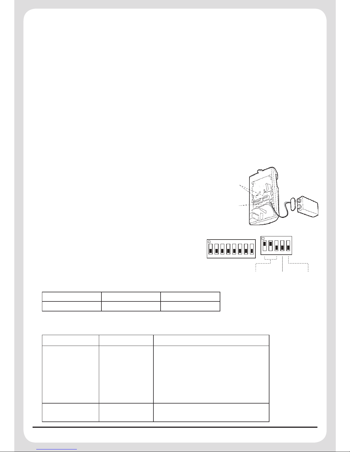
Setting the Remote Control
1. Remove the front cover by undoing the small screw on the rear of the Remote Control.
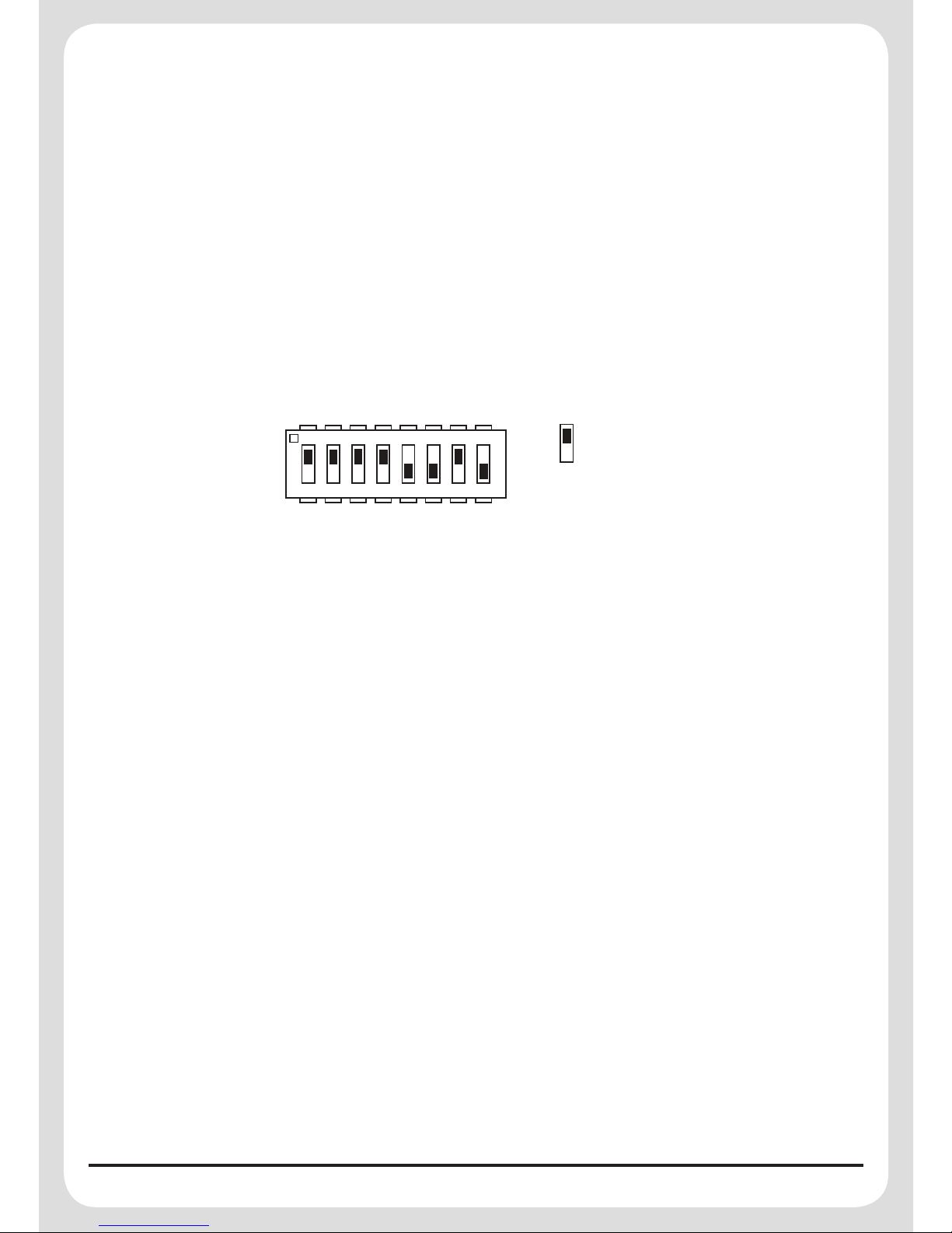
2. Located above the battery is a row of 8 DIP switches.
Select and record a random combination of ‘ON’ and
‘OFF’ positions for the DIP switches. This will be the
system House Code and must be set to the same ON/
OFF combination as the House Code DIP switches in
all other System Devices.
Important: The House Code for your system should
be changed from the factory default setting.
3. To utilise the panic facility on the Remote Control,
remove the Jumper Link. If ‘panic’ is not required
leave the Jumper Link in place.
4. Remove the battery from its packaging and insert it under the clip ensuring that the +v terminal
faces upwards away from the PCB.
5. Replace the front cover and fixing screw.
Testing the Remote Control
1. Press the button. The Transmit LED should illuminate while the button is pressed and
extinguish within 1 second of releasing the button.
2. Press the and buttons in turn to ensure that the Transmit LED illuminates as before.