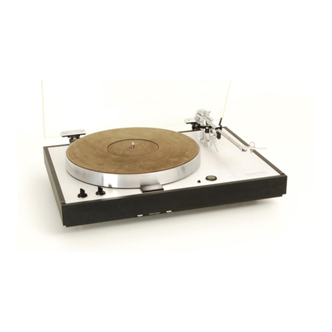
Luxman PD-375 User manual

»
SERVICE
MANUAL
S
FULLY
AUTOMATIC.
TURNTABLE
PD-375

D-375
CONTENTS
FULL-AUTO
MECHA.
TIMING
CHART...
cecscrseccccccncces
EXPLANATION
ABOUT
FULL-AUTO
MECHANISM.
...secceeescee
PB-1373
BLOCK
DIAGRAM.
cccccvccccsvccnccccccceces
aioe
EXPLANATION
ABOUT
TRANSISTOR'S...cccccccccencccssece
MUTING
CIRCUIT
(CANCEL
CIRCUIT).
..ccccccccccccsvoves
MUTING
CIRCUIT
TIMING
CHART...
ccccccccccscccceevecces
PB-1373
TIMING
CHART.
ccccccsccccscccnvccesscccence
PB-1373
CIRCUIT
DIAGRAM.
.cccccccccccvnecs
ovcccescces
MOTOR
SWITCH
CIRCUIT.
.ccccccccnccccccccccccenccscecs
FULL-AUTO
MECHANISM
ALIGNMENT
PROCEDURES.
..sceeceees
FULL-AUTO
MECHANISM
CIRCUIT
ALIGNMENT
ROCEDURES.
....
P.C.B.
ALIGNMENT
PROCEDURES...
.ccccccccccvecacesces
ADJUSTMENT
OF
SW-O7(MAIN
CAM
SW).....
so
ceccecces
coe
PB-1373-1
PARTS
LIST.
ccc
ccceeccevees
ec
ccewcccescces
8
PB-1373-2
PARTS
LIST.
cccecccceces
ccc
ccesces
ooeccces
8
PB-1373-4
PARTS
LIST.
.ccccccccceccccccccees
oocecces
8
FULL-AUTO
MECHA. P.C.B.
PARTS
LIST.
..cccccccccccceeed
PD-375
EXPLODED
VIEN...ccccccccccccccscnccccescceseed
EXPLODED
VIEW
PARTS
LIST.
.ccccccccccvcccccvccescesced
SCHEMATIC
DIAGRAM.
coccecceeccccccecvccccccecsseeeee
ell
°
°
NN
WO
Ww
fF
fF
FW
WwW
N
DH
FF
SPECIFICATIONS
FULL
AUTO
MECHA,
CIRCUIT
TIMING
CHART
33
r.p.m.
45
r.pm.
AC
Motor
Start
‘AC
Motor
Start
OFF
or
Cut
Record
End
OFF
or
Cut
Record
End
42V
Terminal
No.4
|
0
IC
Pin1,2
__
[|
Tie
Wed
ale
si
“aeaweee
LT
BY
IC
Pin
4
[|
an
toPin8
J.
JO
i.
EME
a
IC
Pin
10
|_|
Vee
| |
cs
IC
Pin12
pu
IC
Pin
13
a
oon
fade
a
Pint
—
~~
-
fo
=
i
SW10
Common
|
|
a
42
|
TRO
—
fo
—
=]
-
F.A.M,
AC
Moter
|
=
PD-3
EXPLANATION
ABOUT
FULL-AUTO
MECHANISM
(1)
Normal
(Power
SW
ON
only
in
Play)
Only
NAND
Gate
input
12
is
different
between
33
r.p.m.
and
45
r.p.m.
(2
Rees
Put
on
START/CUT
Button
NAND
Gate
output
10
shall
be
OV,
and
TRO1
and
AC
motor
shall
be
ON.
As
soon
as
AC
motor
has
been
ON,
SW
10
shall
rotate
until
TRO1
becomes
OFF
after
SW
10
on
the
cam
at
the
final
stage
has
again
turned
over
and
the
cam
at
the
final
stage
has
turned
over
half.
=
Ww
Record
End
As
inside
most
diameters
of
LP
and
EP
Groovesare
different
each
other,
operation
is
also
different
(Its
change
can
be
done
by
individual
r.p.m.)
33
L.peM.
When
the
slit
of
Rester
Lever
comes
into
Sensor
Assembly
and
the
photo
transistor
becomes
ON
by
L.E.D.
light,
NAND
Gate
output
11
shall
be
ON
and
ACG
motor
Shall
begin
to
rotate.
45
Y.pem.
When
the
slit
of
Rester
Lever
comes
into
Sensor
Assembly
with
a
photo
transistor's
being
ON
and
the
tonearm
reaches
the
inside
most
with
the
slit's
shutting
off
L.E.D.
light
and
eventually
the
photo
transistor's
being
OFF,
NAND
Gate
output
10
shall
be
OV
and
AC
motor
begins
to
rotate.
(On
this
occassion
when
the
tonearm
returns,
the
slit
of
Rester
Lever
again
passes
through
Sensor
Assembly
and
the
above
mentioned
signal
shall
be
input.
However,
it
is
not
directly
related
since
AC
motor
is
in
operation
by
SW
10.)
(4)
Repeat
When
the
tonearm returns
to
the
armrest
in
REPEAT
mode,
12V
shall
be
loaded
to
the
6P
connector
by
SW
11
and
same
operation
shall
be
made
as
in
case
of
pressing
START/CUT
button.
REMARKS:
As
mentioned
above
be
careful
for
any
light
from
outside
to
come
especially
into
Sensor
Assembly
when
you
are
repairing
since
this
fll-auto
mechanism
is
optical
one.
PB-1373
BLOCK
DIAGRAM
=—
tae
VDS
ON
=
vDS
on
sw|
=)
L
i
ee
MAIN
CAM
GE
ee
Q12
SENSOR
ASS
VDS
OFF
sw)
3.
~
Swo3
|
{
Swot
|
AC
MOTOR
START/CUT
SW\
e
[J
DC
12V
r
“Iv.D.S.
'
MAIN
MOTOR
Cae
Bei
.
ent
REPEAT
i
Ol
|
Swo7
AUTO
FUNCTION
Sw
AUTOUFT
OFF°_
ae
eons
2
TONE
ARM
POSITION
DETECTING
SW

PD-375
EXPLANATION
ABOUT
TRANSISTOR’S
Q
10
280945
When
the
rotation
started
by
depressing
the
"Start/Cut"
button
after
the
suction
by
V.D.S.
button,
this
transistor
works
to
cancel
the
set
signal
to
FLIP-FLOP
circuit
of
"
V.D.S.
on
".
---This
prevents
the
mis-suction
when
the
suction
operates
again
once
already
sucked.
Q
171
280945
When
the
mode
is
set
at
"
REPEAT
",
the
reset
signal
comes
into
the
V.D.S.
off
FLIP-FLOP
circuit.
While
the
V.D.S.
motor
is
rotating,
this
transistor
operates
to
cancel
this
very
reset
signal
until
the
motor
stops
rotating
by
the
reset
Signal
coming
from
SW-07
at
the
main
cam.
---When
the
mode
is
set
at
"
REPEAT
"
while
V.D.S.
motor
is
rotating,
no
problem
to
activate
"V.D.S.
on
".
But
when
the
"V.D.S.
off
"
is
depressed,
V.D.S.
motor
stops
rotating
on
the
way,
and
the
platter
is
locked.
This
transistor
was
adopted
to
avoid
this
trouble.
While
the
reset
signal
of
V.D.S.
off
FLIP-FLOP
circuit
is
to
delete
memory
of
V.D.S.
off.
Q
12
250945
This
works
to
cancel
DC
12V fed
into
V.D.S.
switch
at
the
"REPEAT"
mode.
---This
transistor
is
used
so
that
the
V.D.S.
on/off
switch
should
not
operate
at
"
REPEAT
"
mode.
Q
13-1
28C945
This
operates
to
cancel
not
the
set
signal
to
be
fed
to
V.D.S.
off
FLIP-FLOP
circuit
but
the
set
signal
to
V.D.S.
on
FLIP-FLOP
circuit
except
in
the
case
that
the
tonearm
is
put
on
the
arm
rest
position
by
the
tonearm
position
detecting
switch
09.
Q
13-2
280945
This
operate
to
cancel
the
output
coming
from
"
V.D.S.
on/off
"
FLIP-FLOP
circuit
so
that
the
V.D.S.
motor
should
not
rotate
except
when
the
tonearm
is
at
the
arm
rest
by
the
tonearm
detector
switch
09.
While
when
the
"
V.D.S.
off
"
FLIP-FLOP
circuit
is
set
on,
the
V.D.S.
operation
starts
after
the
tonearm
get
back
to
arm
rest
position.
---This
transistor
is
adopted
so
that
the
platter
should
not
be
mechanically
locked
even
if
"V.D.S.
on/off
"
button
is
switched
on
while
playing.
Q
14
280945
When
the
tonearm
left
from
the
arm
rest,
the
output
of
V.D.S.
on/off
FLIP/FLOP
circuit
is
cancelled
by
Q
13-2.
While
the
tonearm
is
placed
at
the
arm
rest,
V.D.S.
operation
starts,
and
even
if
the
tonearm
left
the
arm
rest
before
the
V.D.S.
operation
completes,
this
transistor
works
to
cancel
this
blocking
signal
until
the
V.D.S.
operation
is
achived.
MUTING
CIRCUIT
(CANCEL
CIRCUIT)
MUTING
CIRCUIT
TIMING
CHART
A
abd
C
SYMBOL
MARK
i
ee
spree
aes
A
B
ere
}
ae

PB-1373
TIMING
CHART
PD-3
MOTOR
SWITCH
CIRCUIT
b
a
ee
ee
er
A
a
—>
DC
20V
i
Q08
J
ey.p.s
Qog9
By
arc
ee
EC)
KC)
MOTOR
SWITCH
CIRCUIT
TIMING
CHART
oT
a
12V
F
or
H
ov
(2
A
0.6V
12V
A
|
|
V
OV
20V
es
We
J
b
oe
‘i
12
Q05~QO80FF
Q05~Q080N
Q05~Q08
OFF
G
|
|
|
te
Q09.
ON
=
=Q09
OFF
Qo9
ON
TeV
TeV
ren
a
or
PB-1373
CIRCUIT DIAGRAM
t—
>
DC12V
VDS
OFF
Lady
SWO3
MAIN
CAM
SW
SWO7
V.D.S.
aeiey
|:
DC
MOTOR
ae?
N.O
9?
N.C
al
lB

pc
wAs)
‘'FULL-AUTO
MECHANISM
ALIGNMENT
PROCEDURES
The
re-alignment
may
be
required
due
to
the
probable
deviation
in
the
measurements
of
the
cartridge
and
disc
employed
although
the
complete
alignment
is
already
made
at
the
factory
side.
(1)
Height
adjustment
of
Arm-Lifter
a.
Set
the
disc
sucked
and
put
the
unit
into
the
playback
mode.
b.
Loosen
the
fixing
screw
for
arm-lifter,
and
adjust
the
height
so
that
the
clearance
between
the
stylus
tip
and
surface
of
the
disc
could
be
procured
by
about
6--8mm.
Remarks:
Proceed
this
alignment
so
that
the
tone-arm
should
not
be
hooked
by
the
arm-rest.
Arm
Rest
.
6~
8mm
Screw
(2)
Lead-In
Adjustment
a.
Obtain
the
playback
mode,
and
press
the
Start/Cut
switch.
b.
Insert
the
(-)
driver
from
the
holes
as
illastrated
in
the
drawing,
and
adjust
the
Lead-In
position
by
rotating
the
eccentric
pin.
33
r.p.m.
and
45
r.p.m.
can
be
adjusted
separately.
Bottom
Plate
(3)
Lead-Out
Adjustment
a.
Insert
the
(+)
driver
from
the
(A)
as
depicted,
and
loosen
the
screw
for
the
sensor
assembly.
b.
Insert
the
(-)
driver
from
the
hole
(B)
as
shown
in
illustration,
and
adjust
the
Lead-Out
position
by
moving
the
position
of
sensor
assembly.
ce.
After
adjustment,
fasten
the
same
screw
explained
in
the
step
(3)-a.
A
B
=
|
Op

PD-3
FULL-AUTO
MECHANISM
CIRCUIT
ALIGNMENT
RROCEDURES
There
happen
to
be
eccentric
record
discs
among
those
which
are
available
in
markets
and
in
case
these
eccentric
ones
are
used
for
playing,
the
wave
form
will
be
as
per
Fig.
1
when
the
rester
lever
slit
passes
through
the
light
axis
of
the
sensor.
f\
of
L
GE
L
Fig.1
When
eccentricity
is
remarkable,
the
wave
form
reads
as
per
Fig.
2
and
mis-operation
shall
be
caused
as
for
EP
discs.
H
Sensor
output
Schmidt
Trigger
Circuit
Level
"H"
Schmidt
Trigger
Circuit
Level
"L"
Sensor
output
L
Fig.2
As
return
action
is
made
on
EP
discs
when
output
of
schmidt
trigger
circuit
comes
to
be
"L"
from
"H",
mis-operation
shall
be
caused
at
the
portion
of
the
enlarged
curve
in
Fig.
2.
So,
prevent
from
mis-operation,
make
the
hysterisis
as
wide
as
possible
and
adjust
output
level
of
the
sensor
to
it.
Widening
of
the
hysteresis
in
schmidt
trigger
circuit
will
be
efective
to
prevention
of
outcoming
noises,
etc.
Adjustments
of
the
hysteresis
and
output
level
of
the
sensor
are
made
respectively
by
the
VRO2
and
VRO1
as
far
as
the
‘present
circuit
is
concerned.
In
the
actual
procedures
firstly
adjust
the
hysteresis
and
secondly
output
level
of
the
sensor.
The
hysteresis
is
not
always
same
since
threshold
value
of
IC's
varies
depending
on
IC's
to
be
used.
So,
at
first
adjust
"H"
level
of
schmidt
trigger
circuit
to
(x-0.8)V
by
the
VRO2
when
output
of
the
sensor
is
"H"
(saturated
state,
provided
to
be
xV),
and
at
this
point
"L"
level
(provided
to
be
yV)
of
schmidt
trigger
circuit
shall
be
decided.
Secondly
adjust
"L"
level
of
output
of
the
sensor
to
(y-0.6)V
by
the
VRO1.
Above
is
all
for
adjustment.
Remarks:
As
to
"H"
level
difference
by
0.8V
is
made
between
threshold
values
of
the
sensor
output
and
schmidt
threshold,
and
as
to
"L"
level
difference
by
0.6V
between
the
threshold
values.
Those
values
are
decided
in
consideration
of
changes
in
temperature,
humidity
and
time
process
and
other
drifts
as
well.

—-D-375
|
P.C.B.ALIGNMENT
PROCEDURES
Set
voltage
for
adjustment
at
11.5
+0.1V
with
use
of
an
EP
disc
and
prevent
the
sensor
from
receiving
external
light.
1,
Adjustment
of
the
VRO2
(adjustment
of
the
hysteresis
in
schmidt
trigger
circuit).
a.
Make
preliminary
adjustment
of
the
VRO2
not
to
make
I.C.
No.4
"H"
from
"L"
when
the
sensor
is
open.
'
ae
Rester
ester
LED
Lever
LED
Lever
=
en
Ass!
Sensor
Ass'y
Fig.3
Sgr
veie
:
CLOSE
b.
Separate
output
of
the
sensor
as
per
the
Fig.4
below
and
put
a
variable
resistor
externally
to
give
output
of
the
sensor
voluntarily.
Photo
Transistor
LK
B
Fig.4
ec.
Measure
"H"
of
output
of
the
sensor
(provided
to
be
V
)
at
the
foregoing
step
a
and
give
voltage
of
(V
-0.8V)
at
the
foregoing
step
b.
d.
At
the
foregoing
step
c
adjust
the
VRO2
to
make
I.C.
No.4
"H"
from
"L".
e.
Separate
the
external
variable
resistor.
2.
adjustment
of
the
VRO1
a.
Make
preliminary
adjustment
of
the
VRO1
not
to
make
1.C.
No.4
"L"
from
"H"
when
the
sensor
is
made
close
from
open.
b.
Adjust
the
VRO1
until
I.C.
No.4
becomes
"L"
from
"H"
when
the
sensor
is
made
open
from
close.
At
this
time
read
out
output
of
the
sensor
and
adjust
the
VRO1
to
make
the
output
-0.6V
right
at
the
moment
when
I.C.
No.4
has
becomes
"L"
from
wytt
‘
ADJUSTMENT
OF
SW-O7
(Main
Cam
SW)
This
alignment
is
needed
in
the
"play"
mode
when
the
charge
lever
cannot
be
opened
sufficiently
or
the
lever
is
going
to
shut
again
causing
irregular
noise
or
preventing
the
platter
from
turning
due
to
the
touch
of
lever
shaft
to
the
platter.
7™N
Main
cam
actuator
|
|
|
Main
cam
|
SW-07
ay
--~
As
the
pivot
of
the
main
cam
actuator
is
eccentric,
you
can
change
the
timing
of
the
SW-07
by
turning
the
pivot
with
a
(-)
screw
driver.
Adjust
the
main
cam
actuator
so
that
the
motor
can
stop
when
the
charge
lever
is
in
the
at
most
open
status
by
pushing
the
V.D.S.
on
switch
(SWO2).
However,
as
the
pivot
of
main
cam
actuator
plays
the
circular
movement,
there
are
two
points
having
the
same
timing
between
the
main
cam
and
main
cam
actuator.
7
Be
sure
of
choosing
the
very
position
which
pushes
the
SW-07
more
than
the
other.
After
adjustment,
do
not
forget
to
put
glue.

PB-|373-!
PARTS
LIST
=)
pC
WASTE
LD
ECW
As)
Remarks
Capacitor:
My...Mylar,
El...Electrolytic,
Ce...Ceramic
PB-1373-2
PARTS
LIST
No. No:
Description
(Transistor)
Symbol}
Stock
eee
No.
Description
(Switch)
Swo1
|
SPO190|Start
Cut
Sswo2
|
SPO190/V.D.S.
On
SWO3
|
SPO190|V.D.S.
Off
No.
No.
TDO1
96
|SLR-
30UR
or
2SD880
or
2SD880
PB-1373-4
PARTS
LIST
Description
iz
e
@
ee
i
PB~1373-4
se
be
2SB435
or
2SB596
28D235
or
2SD880
FULL-AUTO
MECHA.P.C.B.PARTS
LIST
DO1
|
TDO214
DO2
|
TDOL14
DO3
|
TDO214
DO,
|
TDO214
DO5
|
TDOOO1
DO6
|
TDO2Z14A
DO7
|
TDOOR7
DOs
|
TDO139
Silicon
US1035
Silicon
US1035
Silicon
US1035
Silicon
US1035
Silicon
1S4001
Silicon
US1035
Zener
WZ-120
Bridge
SIVB20
=U8'
p—adaa
bh
@
TDQO504
|1
OD-1
TD5012
115953
Symbol}
Stock
No.
No
Description
; : ;
Cae
(Semi-Fixed
Resistor)
COT
CKO157
[0.04
uF
25WV
Ce
C07
[CKO157
[0.04
uF
25wV
Ce
VROT
|
RTQO004
|100K
B
CO2
CE1749
|0.47
uF
5OWV
EL
C08
|CE1703
20
uF
6.3WV
El
C03
CKO157
|0.04
uF
25wV
=
Ce
C09
|CE1720
L7
uF
16WV
EL
CO4
CE1718
22
uF
16WV
EL
C10
|CE1821
|3300
uF
25WV
EL
C05
CE1749
|0.47
uF
SOWV
EL
C11.
|CQ1325
{0.01
uF
50WV
My
C06
CKO157
{0.04
uF
25WV
Ce
(Carbon
Resistor)
ete
ROI
RDOL55
|8.2K
1/3W
R25
|RDO455
|8.2K
1
/3W
RO2
RDOA55
|
8.2K
1/3W
R26
|RDOLA7
|
39K
1/3W
RO3
RDO4L5
|
56K
1/3W
R27
|RDO453
|
12K
1/3W
ROL
RDO4L7
|
39K
1/3W
R28
|RDO455
|8.2K
1/3W
ROS
RDOL52
|
15K
1/3W
R29
|RDOL46
|
47K
1/3W
RO6
RDOAA5
|
56K
1/3W
R30
|RDO4A9
|
27K
1/3W
RO7
RDO457
|
5.6K
1/3W
R31
|RDOAAI
|
27K
1/3W
RO8
RDOL45
|
56K
1/3W
R32
|RDOL455
|
56K
1/3W
ROQ
RDO455
|8.2K
1/3W
R33
|RDOL45
|
56K
1/3W
R10
RDO455
|
8.2K
1/3W
R34
|RDO464
|1.5K
1/3W
R11
RDOA445
|
56K
1/3W
R35
|RDOL48
|
33K
1/3W
R12
RDO447
|
39K
1/3W
R36
|RDO465
|1.2K
1/3W
R13.
|
RDO452
|
15K
1/3W
R37
|RDOLA,
|
68K
1/3W
r=
]
R14
RDO4AI
|
27K
1/3W
R38
|RDOLAL
|
68K
1/3W
R15
RDOALI
|
27K
1/3W
R39
|RDO455
|18.2K
1/3W
R16
RDOLA9
|
27K
1/3W
R40
|RDO450
|
22K
1/3W
R17
RDO450
|
22K
1/3W
R41
|RDO450
|
22K
1/3W
R18
RDO450
|
22K
1/3W
R42
|RS5028
|1.2K
1
W
—-
R19
RDO455
|8.2K
1/3W
R43
|RDO4L7
|
39K
1/3W
R20
RDO450
|
22K
1/3W
R44
|RD2578
|680
1/2W
R21
RDO455
|8.2K
1/3W
R45
|RD2588
|1.8K
1/2W
R22
RDOL457
|5.6K
1/3W
R46
|RD2588
|1.8K
1/2W
R23.
=|}RD2586
|1.5K
1
/2W
R47
|RDO466
|
1K
1/3W
8
R24
RDO452
|
15K
1/3W

PD-375
EXPLODED
VIEW
PD-375
PD-375
|PD-375
PD375
|
-EXPLODED
VIEW
PARTS
LIST
Exploded
View
Parrts
List
AG...240V
(With
Line
Voltage
AZ.
..120V
(With
Line
Voltage
Selector)
Selector)
Simpor[stcck
—[pesoription
[bel]
Sse
7
[UN1031-B
|Sealing
Pad
(out)
62
|
YAA30A18
2
|UN1032-E
|Sealing
Pad
(in)
63
|YAA3OAO4
3.
+|UN1039
Coil
Spring
64
|YAA40CO8
4
|UN1254
Turn
Table
65
|
YAA4OA12
5
1UN1255
Sucking
Core
66
|
YNKO4OA
6
{021257
Sucking
Plate
67
|
YNKO30A
7
(UZ1292
Roller
Plate
68
|
YWIO025C
8
|W21154
Spring
69
|YJB30A06
9
|AHOO16
Fuse
Holder
(UZ)
70
|YZBO30H
AHOO19
Fuse
Holder
(AK,AG)
71
|YZBO40H
10
AM1008
DD
Motor
PHM6002P~-01
72
|YCG31A13
11
ATO069
Terminal
Plate
73
|¥CG31A10
12
|BFOO72
Fuse
0.3A
(UZ)
74
|Y¥CG27A08
BFO201
Fuse
0.1AT
(AZ)
75
|YWZ030W
BF0217
Fuse
0,08
AT
(AG,AK)
76
|Y¥CD26C04
13
|BKOO18
AC
Cord
(U)
77
|YND120A
BKO022
AC
Cord
(AK)
78
|YWA120A
BK0023
AC
Cord
(AG)
79
|YAA30C06
14
BZ0023
Cord
Clamp
80
|YWEO4OM
15
|PT2546
Power
Trans(U)
81
|YAA4OA20
PT2548
Power
Trans
(AK,AG)
82
|YWAO4OT
16
SP0191
GV
Switch
83
|MH1004
le
SRO1
58
Rotary
Switch
84
|YAA30A06
18
|UE1112
Bottom
Plate
90
|WZ1192
19
|UR1319
Bracket
91
|WZQ0018
20
|US0003
P.C.B.
Stand
92
|WDQO0010
21
US5023
Stand
93
|WZQ001
5
22
|uu1041
Lifter
Spring
94
|WZQ0016
23
UW11
31
Insulator
Column
95
|WZ1191
24
UW11
39
Spacer
96
|WZQ0018
25
UW1140
Spacer
97
|WZQ0017
26
UZ1114
Bind
Bracket
100
|UZ1285
28
UZ1
282
Switch
Lever
01
}|U0Q0006
29
UZ1
283
Lift
Bearing
102
|U0Q0007
30
UZ1
284
Lift
Shaft
103
|BXQO0001
31
UZ1286
Insulator
Spacer
104
|AMQO102
32
}WA1231
Aluminum
Panel
A
105
|SPQO0008
33
A1232
Aluminum
Panel
B
106
|APQO010
34
WB1093
Cabinet
107
|SPQOO004
35
D1135
Escutcheon
108
|APQO010
36
W21145
Lifter
109
|SPQO0005
37
Z1148
Main
Insulator
110
|U0Q0008
38
W21189
Cabinet
Insulator
111.
|U0Q0009
39
UW1137
Spacer
112
|UUQO0001
40
UZ1277
Hinge
113
jUUQO002
AI
UZ1278
Hinge
Holder
114
|UZQ0003
42
{|WD1134
Escutcheon
120
|UZ1279
43
WE1
098
Edge
Protector
121
|UAQO002
AA
wWJ1093
Knob
122
|U0Q001
3
45
|wWJ1152
Knob
(Start/Cut)
123
|U0Q0014
46
|WI1154
Knob
(V.D.S.
ON/OFF)
124
|U0Q0010
47
W21147
Dust
Cover
125
|U0Q0011
48
W21158
Cap
126
|U0Q0012
49
|WZ1178
Bushing
127
|BXQO0002
51
|WZ1160
Record
Sheet
128
|UZQ0004
52
BKO063
Arm
Cable
129
|AMQO103
53
|AM1008
Motor
P.C.B.-
130
|UNQO001
54
|P1373-1
PB1
373-1
131
|SPQO0009
55
|P1373-2
|PB1373-2
132
|UZQ0105
56
|P1373-3
|PB1373-3
133
|UUQ0003
57
|P1373-4
|PB1373-4
134
|SPQO0010
58
|UQQ0005
|Restor
Lever
Ass'y
135
|UNQO002
59
UR1341
Motor
Holder
Bracket
136
|UZQ0005
60
|¥CG24C10
|Round
Tapping
2.4x10
137
|UUQO0O4
61
|¥CG31C10
|Round
Tapping
3.1x10
Remarks:
U....120V
For
North
America.
A)
AK...220V
(With
Line
Voltage
Selector)
Description
Binding
3x18
Binding
3x4
Binding
4x8
BK
Binding
4x12
Flange
Nut
B-5
Flange
Nut
B-6
E
Ring
2.5
Bind
Tapping
3x6
Earth
Lug
Earth
Lug
Round
Tapping
3.1x13
Round
Tapping
3.1x10
Round
Tapping
2.7x8
Fiver
Washer
3
Allen
Fex.
Set
2.6x4
VR.
Nut
12PM
Flat
Washer
12VP
Binding
3x6
BK
External
Lock
Washer
Binding
4x20
Flat
Washer
4
Caution
Seal
Binding
3x6
Tone
Arm
Ass'y
Weight
Ass'y
Arm
Base
IFC
Ass'y
Arm
Rest
Clip
Head
Shell
Cartridge
Wire
Arm
Lifter
Lever
Full
Auto
Mecha
Ass'y
Gear
Cam
Ass'y
Pulley
AC
Motor
Ass'y
Micro
Switch
Sensor
Ass'y
Micro
Switch
P.C.B.
Ass'y
Micro
Switch
Manual
Selector
Ass'y
Brake
Lever
Ass'y
Tension
Spring
Tension
Spring
Belt
288
Mecha.
Chassis
Unit
VDS
Base
Plate
Ass'y
Charge
Lever
Ass'y
L
Charge
Lever
Ass'y
R
Main
Cam
Gear
Gear
3
Gear
4
Pulley
Belt
375
Motor
(VDS)
Motor
Cushion
Micro
Switch
A
Switch
Holder
Tension
Spring
Micro
Switch
B
Cushion
Column
375
Charge
Lever
Spring
For
Europe,
South
East
Asia.
For
England,
Australia.
For
North
America,
South
Asia,
East
Asia.

SCHEMATIC
DIAGRAM
swos
N.C
4
Cr
NO
swit
UU
N.C
cy
NO
ae
¥
o
Q
$\z
wow
SOLENOID
ON
30cm
RECORD
OFF
17cm
RECORD
Ba
cm
RO9
100K
>t
2
”
la
te
gf
i
a|
al
78
|.
a
zt
a}
8
AC.
MOTOR
(FULL
AUTO
MECHANISM
)
[ew
te
oe
a
Sk
ee
ee
ee
ee
1
a7
5
po
O-O-O-0-0-O-
-0--
|
a
1
TJ
!
G
Q
fe
'e)
H
mS
~
1
A
.
.
os
Qi7
|
C21
0.047
;
Swo3
SW02
SWO1
L_
PB-1373-2
00
R14
18K
[rr
-
VR3
6.8K
Q10,
11,
14,
15
ad
DCW
AoW
ad
DCW
ho)
ROT
8.2K
RO3
56K
Cos
47-16V
2
c
ag
AG-MODEL
(240V)
120
100,
Us)
1
ad
i
P.2548
tJ
AK-MODEL
(220V)
i
AZ-MODEL
(120V)
008
S!VB20
120
BLU
R45
1.8K-'2W
ROO
8.2K
R22
5.6K
R21
82K
U-MODEL
(120V)
es
ae
R11
56K
R12
39K
V7
2
3
Q
Co
=,
5
x
8
ND
(yy
R27
CJ
=
o>
any
GND
SWO1
START
/CUT
SW.
(PB-1373-2)
SWO2
V.D.S.
ON
SW.
(PB-1373-2)
SWO3
V.D.S.
OFF
SW.
(PB-1373-2)
SWO04
POWER
SW.
SWO5
(POWER
SW.
&)
SPEED
SELECTOR
SW.
1.
OFF
2.
33-1/3
R.P.M
3.
45
R.P.M
SWO6
FUNCTION
SW.
1.REPEAT,
2.AUTO,
3.
AUTO
LIFT-OFF
SWO7
MAIN
CAM
SW.
SWO8
D.D.
MOTOR
SW.
SWO9
TONE-ARM-POSITION
DETECTING
SW.
SW10
F.A.M.
RELAY
HOLD
SW.
SW11
F.A.M.
REPEAT
SW.
R13
15K
C03
0.04
R28
8.2K
|
:
|
a6
28B435
|
a06
2SA992
\
Q08,
09,
17
280235
|
Q01~05,07,10~15
2SC945
{|
DO1~04,
06
US1035
|
|
|
|
!
\
'
Ci
OM.
G)
ss
oe
com.
@)
+
Y,
(8)
COM.
oy
Ie
®
(16)
ROTARY
SW.
(BOTTOM
VIEW)
COM.
pee
ac
RED
©
vio
GRN
ZD1-—s-RD9.1EB2
D1~4
VvD1222
28C1213
X-tal
~LSS-002-0
28C
1449
!
48
P.
|
A
|
I
cas
>
Fe
!
—!-,
sey
te)
(eb
Sat
'
———————
e084
0
as
a6
om
l
=
23
2
\
ce
3
H
(i?
!
a i
KD
GA)0"7
2
D.D.
MOTOR
PHM-6002P-01
jars
SY,
:
|
83.
8
!
'
1,
Unless
otherwise
specified,
all
resistors
are
in
ohm,
all
capacitors
are
in
micro
farad.
[A
[PD-375
|
1
2.
Transistors
ICs
and
diodes
may
be
replaced
with
any
types
having
comparable
ratings.
H
3.
Due
to
continued
research
for
improvements.
Lux
reserves
the
right
to
alter
the
circuit
and
specifications.
1
10
Printed
in
Japan

SPECIFICATIONS
(Phono
Motor
Section)
*Driving
System:
*Moter:
*Turntable
Platter:
*Rotation:
*aejustebleRange—ef
Rete-tienm-
*S/N
Ratio:
*Wow
&
Flutter:
CTonearm
Section)
*Tonearm:
“Effective
Length:
*Tracking
Error:
*Qverhang:
*Cartridge
Weight:
“Cartridge
Height:
*Stylus
Pressure:
*Accessories:
CAddtional
Features)
*Dust
Cover:
*Automatic
Function:
(General
}
*Power
Consumption:
*Dimensions:
*Weight:
Direct-Drive
System
DC-servo
brushless
&
Slotless
quartz-locked
motor
30cm
aluminiumdie-cast
with
built-in
VDS
pump
(2.5
kgs)
33-1/3
rpm,
45
rmp
(2-speed)
13%
better
than
7O0dB(DIN
B)
no
more
than
0.03%
W.R.M.S.
Straight
Arm
of
static
balance
type
230mm
42°12!
7
30!
1
6mm
5g~10g
16mm~19mm
(by
use
of
spacers)
O~3g
(direct
reading)
Anti-skate
adjustment
Detachable
with
semi-freestop
hinge
Auto-Lead-In(Auto
Start),
Auto-Repeat,
Operation
Mode
Selector(repeat,
auto,
auto-lift-off),
Start/Cut
Button
1OW(CSA
rated)
438
(W)
x
165
(H)
x
365
(D)
mm
(13.9"
x
6.4"
x
14.6"
)
Net
1055:
Kes:
(23931
1
pes.)
Gross
12.0
kgs
(26.4
lbs.)
Specifications
and
appearance
design
subject
to
change
without
notice.
Table of contents
Other Luxman Turntable manuals

Luxman
Luxman PD277 User manual

Luxman
Luxman PD-171AL User manual

Luxman
Luxman PD-171A User manual

Luxman
Luxman PD-121 User manual

Luxman
Luxman PD26 User manual

Luxman
Luxman PD277 User manual

Luxman
Luxman PD444 User manual

Luxman
Luxman PD-151 User manual

Luxman
Luxman PD-151 User manual

Luxman
Luxman PX-101 User manual