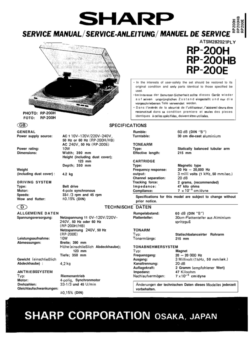
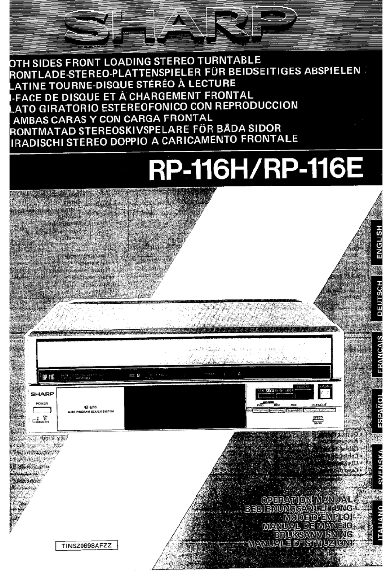
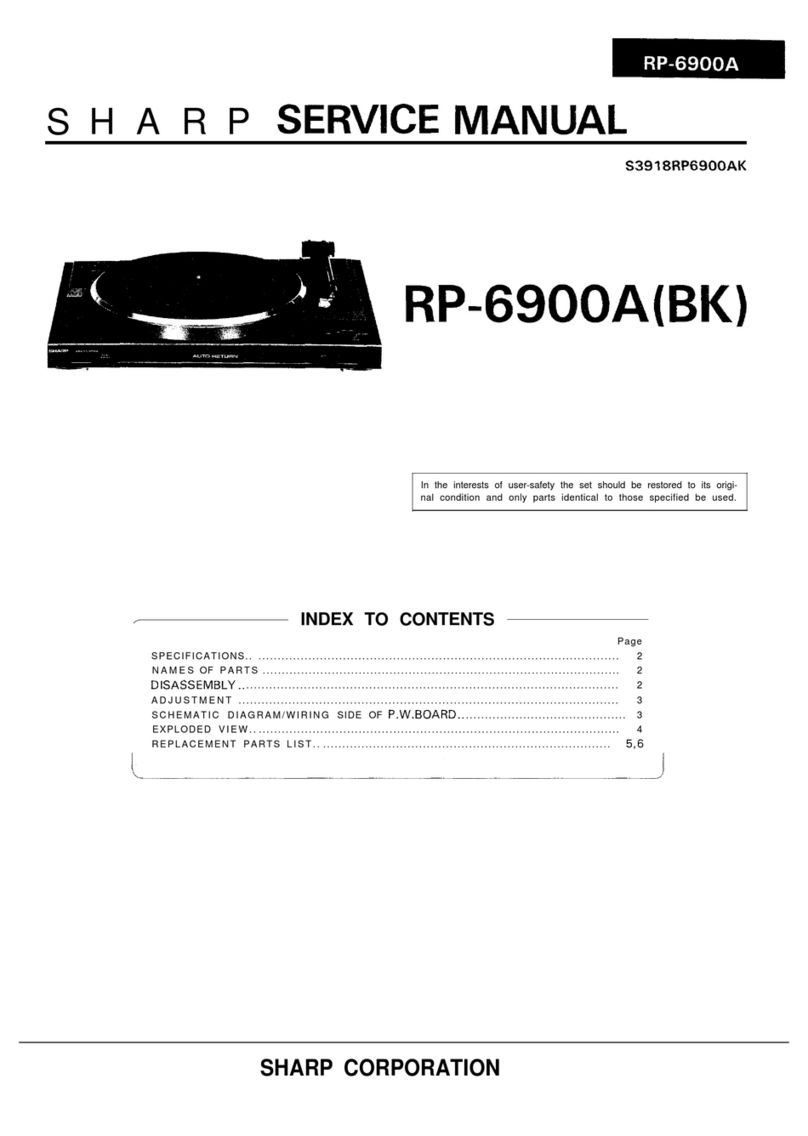
Sharp RP-32 Series User manual

mmm
SHARI=
S6458RP-32HS/
RP=32H(S)(BR)(BK)
RP=32E(S)
PHOTO:
RP-32H(S)
l
In the interests of user-safety the set should be restored to its
original condition and only parts identical to those specified be
used.
l
Im
lnteresse
der Benutzer-Sicherheit
sollte
dieses Gerat wieder auf
seinen
urspriinglichen Zustand eingestellt
und
nur die
vorge-
schriebenen Teile verwendet werden.
. Dans I’interdt de la
sdcurite
de I’utilisateur, I’appareil devra
Btre
reconstitute dans
se
condition premiere et
seules
des
pieces
identiques
a
celles
specifiees,
doivent
Btre
utilisees.
INDEX TO CONTENTS
--.
0
Page Page
SPECIFICATIONS . . . . . . . . . . . . . . . . . . . . . . .
.2,3
NOTES ON SCHEMATIC DIAGRAM . . . . . . . . . .
.8,9
NAMESOFPARTS . . . . . . . . . . . . . . . . . . .
..a
.2,3
SCHEMATIC DIAGRAM AND WIRING
CARTIRDGE REPLACEMEMT . . . . . . . . . . . . . , . . 4 SIDE OF
P.W.BOARD
. . . . . . . . . . . . . . . . . . . . .
IO
PACKING METHOD (FOR UK) . . . . . . . . . . . . . . . . 5 EXPLODED VIEW . . . . . . . . . . . . . . . . . . . . . . . .
11
DlSASSEMBLY..........................6,7
REPLACEMENT PARTS LIST . . . . . . . . . . . . . . .
12
MECHANICAL ADJUSTMENT . . . . . . . . . . . . . .
6,7
@
INHALTSVERZEICHNIS
Seite Seite
TECHNISCHE DATEN . . . . . . . . . . . . . . . . . . . .
.2,3
SCHEMATISCHER SCHALTPLAN UND
BEZEICHNUNG DER
TEILE
. . . . . . . . . . . . . . . .
.2,3
VERDRAHTUNGSSEITE DER LEITERPLATTE , .
10
AUSWECHSELN DES TONABNEHMERSYSTEMS . . . 4 EXPLOSIONSDARSTELLUNG . . . . . . . . . . . . . . .
11
ZERLEGEN
,...........................6,7
ERSATZTEILLISTE..
. . . . . . . . . . . . , . . . . . . . .
12
MECHANISMUSEINSTELLUNG . . . . . . . . . . . . .
6,7
ANMERKUNGEN ZUM SCHEMATISCHEN
SCHALTPLAN . . . . . . . . . . . . . . . . . . . . . . ...8.9
0
TABLE DES
MATIERES
Page
CARACTER~STIQUES . . . . . . . . , . . . . . . . .
.2,3
DIAGRAMME SCHf?MATIQUE ET COTE CABLAGE
Page
NOMENCLATURE. . . . . . . . . . . . . . . . . . . . . . .
.2,3
DE LAPLAQUETTE DE MONTAGE IMPRIME . . . IO
REMPLACEMENT DE LA CELLULE . . . . . . . . . . . . 4
VUE
E
N
&LATE
D~MONTAGE
11
6,7
RkiLAGE
DE
hi&Ikti;
:
:
:
:
:
:
:
:
:
:
:
:
:
:
:
:
‘6.7
LISTE DES
PIhE&%
kECH’i&%’
:
:
:
:
:
:
:
:
:
:
:
12
REMARQUES CONCERNANT LE
DIAGRAMME
SCHiMATlQUE
. . . . . . . . . . . . .
.8,9
/
SHARP
CORPORATION

Type:
Semiconductor:
Speed:
Motor:
Wow and flutter:
S/N ratio:
output:
Frequency response:
Tracking force:
FOR A COMPLETE DESCRIPTION OF THE OPERATION OF THIS UNIT,
PLEASE REFER TO THE OPERATION MANUAL.
Direct drive, semi-automatic
8 Transistors
2 Diodes
3 Hall Ellements
33-l/3
and 45 rpm
DC Servo Motor
50.08% (DIN 45 500)
65
dB
(DIN
B)
3 mV (1 kHz, 50 mm/set)
20
-
20,000 Hz
2.5
g
(recommended)
1.
17
cm (7”) EP Record Adaptor
2.
Center Spindle
3.
Turntable Sheet
4.
Turntable
5.
Tonearm
6.
Tonearm
Counterbalance Weight
7.
Cue Lever
8.
Cartridge
9. Cut Button: Cut
10.
Speed Selector Button: SPEED
11.
Input/Output Plug
SPECIFICATIONS
Tonearm: Static balanced
Cartridge: Magnetic type (CART-137)
Replacement stylus:
STY- 137
Dimensions: Width; 430 mm (17”)
Height; 108 mm
(4-l/4”)
Depth; 367 mm
(14-7/16”)
Weight:
2.5 kg (5.5
Ibs)
Specifications for this model are subject to change
without prior notice.
NAMES OF PARTS
Figure 2-l
Figure 2-2
-2-

POUR LA DESCRIPTION COMPLETE DU FONCTION-
NEMENT DE CET APPAREIL, SE REPORTER AU
MODE D’EMPLOI.
EINE VOLLSTANDIGE BESCHREIBUNG DER
BE-
DIENUNG
DIESES
GERATES
IST
IN DER BEDIENUNG-
SANLEITUNG ENTHALTEN.
TECHNISCHE DATEN
TYP:
Riemenantrieb halbautomatisch
Bestbckung:
8 Transistoren
2 dioden
3 Hall Elements
Drehzahlen:
33-1
I3
und
45 U/min
Motor: Gleichstromservomotor
Gleichlaufschwankungen:
?0.08%
(DIN 45 500)
Rauschabstand:
65
dl3
(DIN
B)
Ausgang:
3 mV
(1
kHz. 50
mm/s)
Frequenzgang:
20-20
000 Hz
Auflagekraft: 2.5 g(empfohlen)
Tonarm: Gewichtsbalanciert
Tonabnehmersystem: Magnetischer Typ (CART-1371
Ersatznadel:
STY-l 37
Abmessungen:
Breite: 430 mm
Hohe:
108
mm
Tiefe: 367 mm
Gewicht:
2.5 kg
Die technischen Daten
fiir
dieses
Model1
kiinnen ohne vor-
herige Ankiindigung iinderungen unterworfen sein.
BEZEICHNUNG DER
TEILE
I.
Mittelstiick
fiir
17
cmSingleplatten
2.
Mittelachse
3.
Plattentellerblatt
4.
Plattenteller
5.
Tonarm
6.
Tonarm-Gegengewicht
7.
Tonarmlifthebel
8.
Tonabnehmersystem
9.
Unterbrechungstaste: CUT
10.
Drehzahlwahltaste: SPEED
11.
Eingangs-IAusgangsstecker
CARACTERISTIQUES
Type
:
Entrainement direct,
semi-automatique
Semiconducteur: 8 Transistors
2 Diodes
3
Cellules
2
effet Hall
Vitesse:
33
l/3
et 45 t/mm
Moteur: Servo-moutter CC
Pleurage et scintillement:
50.08%
(DIN 45 500)
Rapport
S/B:
65
dB
(DIN
B)
Sortie: 3
mV
(1
kHz,
50 mm/s)
Reponse
de
frequence:
20
A
20.000 Hz
Force d’appui: 2.5
g
(recommandee)
Bras de lecture: Bquilibrage
statique
Cellule: Type
magnetique
(CART-1371
Aiguille
de remplacement: STY-137
Dimensions:
Largeur: 430 mm
Hauteur: 108 mm
Profondur: 367 mm
Poids: 2.5 kg
Les caracteristiques de ce
modele
sont
sujettes
I
modifica-
tion
sans
preavis.
NOMENCLATURE
1.
Adaptateur de
disque
45 tours
(17cm)
2.
Mandrin central
3. Feuille de plateau
4. Plateau
5. Bras de lecture
6.
Contrepoids drequilibrage
7. Levier de mise en pile
8.
Cellule
9. Bouton de coupure: CUT
10.
Bouton de selection de vitesse: SPEED
11.
Fiche d’entree/sortie
-3-

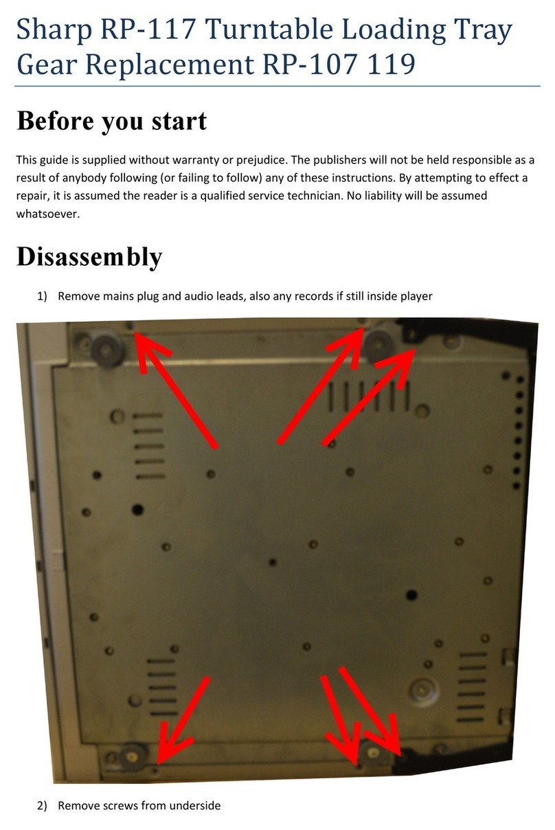
DISASSEMBLY
Caution on Disassembly
Follow the below-mentioned notes when disassembling the
unit and reassembling it, to keep its safety and excellent
performance:
1. Take out a record of the unit.
2. Be sure to remove the input/output plug from the
SM-32H/E
before starting to disassemble the unit.
3. Take off nylon bands or wire holders where they need
be removed when disassembling the unit. After servicing
the unit, be sure to rearrange the leads where they were
before disassembling.
4. Take sufficient care on static electricity of integrated
circuits and other circuits when servicing.
Figure 6-l
STEP REMOVALPROCEDURE FIGURE
1
,
1
Turntab,e
1
l.Turntablesheet
(Alxl
1
6-,
2.Turntable
stopper
(B)xl
Bottom plate 1 .Screw (C)x3
2. Bottom Plate stopper
(D)xl
6-2
J
MECHAN
I
CAL ADJUSTMENT
TOP VIEW
Connect the Input/output plug to the amplifier
(SM-32H/E),
or supply +12V by an external DC power supply.
REMARKS
ITEM JIG
Bladed screw
driver
LP record or
Test record
SSR-4001
(SIDE
1)
SSR4002
LP record
which is
provided with
Strobe viewer
ADJUSTMENT
POINTS
Auto return
adjustment cam
*
See Fig. 6-3,
6-4.
Auto return Clockwise or
counterclockweise
Auto return count
7-B
(using a test record
Adju
Cam
1
33-l
/3
r.p.m.
speed:
VR33
45 r.p.m. speed
:
VFi45
Phono Motor is
kept in rotation,
Phono motor
rotational
speed
Figure 6-4
\
BOTTOM VIEW
,,
Adjustment Cam
PHONO MOTOR
Ml01
Figure 6-3 Figure 6-5
-6-

PACKING
METHOD
(FOR
UK)
9.
10.
11.
12.
13.
14.
Label, MADE IN JAPAN TLABJ0006AFZZ
Polyethylene Bag, Set SPAKP0445AFZZ
Protection Sheet SPAKX0835AFZZ
Polyehylene Bag, Turntable
SSAKP048
1
AFZZ
Packing Add, Right SPAKAI 286AFZZ
Packing Add, Left SPAKAI 285AFZZ
Packing Case
SPAKC3075AFZZ
Packing Add, Back
SPAKX1409AFZZ
Polyethlyene
Bag,Tonearm
Weight SPAKA0036AFZZ
Protection, Arm SPAKX1326AFZZ
Protection, Turntable SPAKAI 298AFZZ
Label, Caution TCAUZ0039AFZZ
Label
TLABP0295AFZZ
Protection, Turntable SPAKX 1407AFZZ

CARTRIDGE REPLACEMENT
A suitable cartridge has a weight range from
4g
to
6g
and the
distance from stylus tip to the top of cartridge does not
exceed
17mm.
Read the manufacturer’s fitting instructions
carefully before installing a cartridge into the
headshell
of the
RP-32HlE.
1. Slide the output lead connectors onto the new cartridge
terminals, taking care to observe correct polarity.
Blue lead . . . . . . , . .
.Left
channel Earth
White lead . . . . . , . .
#Left
channel
Red lead . . . . . . . . . *Right channel
Green lead . . . . . , . .
*Right
channel Earth
2. Place the cartridge into the
headshell
with a distance of
52mm between the stylus tip and the end of the
headshell.
l
On this unit the
headshell
cannot be removed from the
tonearm.
3. The tracking force will require readjustment because the
cartridge weights differ.
Figure 4-l
AUSWECHSELN DES TONABNEHMERSYSTEMS
Das zu verwendende. Tonabnehmersystem hat ein Gewicht 2.
Das
Tonabnehmersystem in den Tonabnehmertrager so
ein-
von 4
g
bis 6
g.
Der Abstand zwischen der Nadelspitze
und setzen,
daR
der Abstand zwischen der Nadelspitze und dem
Tonabnehmeroberseite ist
weniger
als
17 mm. Ende des
Tonabnehmertagers
52 mm betragt.
Die Montagehinweise des Herstellers vor Einsetzen des Ton- * Der Tonabnehmertrlgers dieses Gerltes kann nicht von
abnehmersystems in den Tonabnehmertrager des
Modelles
dem Tonarm entfernt werden.
RP-32H/E
aufmerksam
durchlesen.
3. Die Auflagekraft
mu6
nueu eingestellt werden, da die Ton-
1. Die
Ausgangsleitungsanschliisse
in die Klemmen des
Ton-
abnehmergewichte unterschiedlich sind.
abnehmersystems einsetzen
und
dabei auf die richtige
Polaritlt
achten.
Blaue
Leitung . . . . . Erdung
fiir
linken Kanal
Weil3e
Leitung , . . . . Linker Kanal
Rote Leitung . . . . . ,
Rechter
Kanal
Griine Leitung . . . . . Erdung
fiir
rechten Kanal
REMPLACEMENT DE LA CELLULE
Une cellule
appropriee
presente
une gamme de poids entre 4
g
et 6
g
et la distance entre la pointe de
I’aiguille
et la partie
superieure
de la cellule ne
depasse
pas 17mm. Lire
les
instruc-
tions de montage fournies par
le
fabricant avant d’installer
une
cellule dans la tete de lecture de la
RP-32H/E.
1. Faire glisser
les
connecteurs
des
fils
de sortie
sur
les
bornes
de la nouvelle cellule, en veillant
a
la polarite correcte.
Fil bleu . . . . . . , . . . Mise
a
la terre du canal gauche
Fil blanc . . . . . . . . . Canal
gauch
Fil rouge . . . . . . . . . Canal droit
Fil vert . . . . . . . . . . Mise
a
la terre
du
canal droit
2. Placer la cellule dans la
t&e
de lecture
avec
une
distance de
52mm entre la pointe de
I’aiguille
et
I’extremite
de la
t&te
de lecture.
l
Sur cet appareil, la
t&e
de lecture ne peut pas
etre
retiree
du
bras de pick-up.
3. Les poids des ensembles de cellules different
les
uns des
autres
de
telle
sorte
qu’il
est
necessaire
de refaire
le
reglage
de la force d’appui en
fonction
du
pids.
-4-
I-
I
I
2
I
3
I
4
I
5
1
6
05
I
12
/’
IO
Figure
11
EXPLODED VIEW
-ll-

PHONO MOTOR
ACET.“PI”
‘~”
;
PLAYER SIGNAL
I
I
CNSIOZ
1
I
,R-ch
I
I
IL-ch
I
-I
‘0
I
E
NOTES ON SCHEMATIC DIAGRAM can be found on page 8.
0
D
ANMERKUNGEN ZUM SCHEMATISCHEN SCHALTPLAN stehen auf Seite 9.
OREMARQUES
CONCERNANT LE DIAGRAMME SCHEMATIQUE sont indiqub
g
la
page 9.
Figure 10 SCHEMATIC DIAGRAM AND WIRING SIDE OF
P.W.BOARD
-1
o-

ZUR
BEACHTUNG
.
Bei
diesen
schematischen Schaltplan handelt es
sich
urn
den
einer typischen Einheit des Motors (RMoTV0184AFZZ).
l
lndividuelle
Einheiten des Motors (RMoTV0184AFZZ) sind
ih ihrer Leistung ein wenig verschieden, und die in
jede
Einheit eingeschlossenen
Widerstsnde
und Kondensatoren
sind von jenen in andere eingeschlossenen Verschieden.
Daher ist es empfehlenswert, den Motor nicht
zu
reparieren,
wenn der defekt ist. In
diesem
Falle
den gegen einen neuen
answechseln.
ANMERKUNGEN ZUM
SCHEMATISCHEN SCHALTPLAN
l
Widerstande:
Urn
die Einheiten der
Widerstande
unter-scheiden zu
konnen,
werden Symbole wie
K
benutzt.
Das
Symbol
K
bedeutet 1000 Ohm 8ei
Widerstanden
ohne Symbol
handelt es
sich
urn
ohmsche Widerstande.
l
Kondensatoren:
Zum
Bezeichnen
der Kondensatoreinheit wird das Symbol
P
benutzt; dieses Symbol
P
bedeutet Nanofard. Die Einheit
eines Kondensators ohne Symbol ist Mikrofarad. Fiir
Elektrolytkondensatoren wird die Be-zeichnung
“Kapazitlt-
I
Stehspannung” benutzt.
l
Anderungen
des schematischen Schaltplans und der
Ver-
drahtungsseite der Leiterplatte
fiir
dieses
Model1
im Sinne
von Verbesserungen jederzeit vorbehalten.
PI&CAUTIONS
l
Ce diagramme
schematique
est base
sur
celui du moteur
(RMoTV0184AFZZ).
9
La performance du moteur (RMoTV0184AFZZ) varie
legerement
selon
les
unites.
II en va de
m&me
pour
les
resis-
tances et condensateurs utilises dans
le
moteur.
II
est
done
recommande,
en cas de panne, de remplacer
le
moteur par un neuf
plutot
que de
le
reparer.
REMARQUES CONCERNANT LE
DIAGRAMME SCHEMATIQUE
l
Resistance:
Pour
differencier
les
unites de resistances, on utilise des
symbole tels que K:
le
symbole
K
signifie
1000
ohms et la
resistance
donnee
sans
symbole
est une resistance de type
ohm.
l
Condensateur:
Pour indiquer
I’unite
de condensateur, on utilise
le
symbole
P; ce symbole
P
signifie micro-microfarad, et
I’unid
de
condensateur
donnee
sans
ce symbole est
le
microfarad. En
ce qui
concerne
le
condensateur Blectrolytique, on utilise
I’expression “tension de regime/capacite”
l
Le diagramme
schematique
et
le
cot6
cablage
de la
PMI
de
ce
modele
sont sujets
a
modifications
sans
preavis
Pour
I’amelioration de ce produit.

0
03
0
REPLACEMENT ERSATZTEILLISTE
LISTE DES
PIECES
PARTS
LIST
DE
RECHANGE
“HOW TO ORDER REPLACEMENT
PARTS”
To
have
your order filled promptly and
correctly.
please
furnish the following
information.
1. MODEL NUMBER
2.
REF. NO.
3. PART NO.
4. DESCRIPTION
REF.NO.
BllOl
81102
CNPlOl
CNPlOP
CNP103
CNP104
CNSlOl
CNSlO2
CNS103
CNS106
Ml01
SW101
SW102
5
“BESTELLEN
VON
ERSATZTEILEN”
Urn
lhren Auftrag schnell und richtig
ausfuhren
zu
kannen, bitten wir
urn
die
folgenden Angaben.
1. MODELLNUMMER
2. REF. NR.
3.
TEIL
NR.
4.
BESCHREIBUNG
PART NO. DESCRIPTION
CODE
REF.NO.
CIRCUIT PARTS
QCNCM095BAFZZ
QCNCM233DAFZZ
QCNCM462BAFZZ
QCNCM32OEAFZZ
QCNW-2463AFZZ
QCNW-2697AFZZ
QCNW-2696AFZZ
RMoTV0184AFZZ
QSW-M0073AFZZ
QSW-PSI
75AFZZ
Connector
4Pin.Part
of
-
CNS106
Connector
2Pin.Part
of
-
CNS106
Plug,2Pin AB
Plug.4Pin AC
Plug,
2Pin
AA
Plug,5Pin AC
Input/Output
Cord AM
Input/Output
Cord,Part
of
-
CNSlOl
Connector Assembly 2Pin A
B
Connector Assembly
5-4-
A
E
2Pin
Motor With P.W.Board
B
G
Assembly
Switch,Motor
AF
Switch,Speed 33-45 AE
EXPLODED PARTS
PSPAi0290AFZZ
Cushion
AA
GCABA1920AFSA Cabinet(S) AY
GCABA192OAFSB Cabinet,H(BR) AY
GCABA1920AFSC Cabinet,
H(BK)
AY
GFTAU6021AFZZ Bottom Plate AH
JKNBMU552AFSE
Button,Operation,(S)
AE
JKNBM0552AFSF
Button,Operation,H(BR/
A
E
W
JPU-P0074AFSA
Tonearm Assembly With
B
A
Is-1
Cartridge
-
Tonearm
-
I
5-2
5-3
5-4
6
a
9
10
11
12
13
14
15
16
17
ia
19
20
21
22
RCTRE5066AFSA
PNDLD0067AFZZ
LHLDW1003SE06
LHLDW1075AFZZ
LANGK0427AFZZ
MARMP0023AFZZ
MARMP0025AFZZ
MLEVF1553AFZZ
MLEVF1554AFZZ
MLEVF1662AFZZ
MLEVP0119AFSA
MLiFPOOO7AFSC
MSPRC0529AFFJ
MSPRK0067AFFJ
MSPRT1050AFFJ
MSPRT1134AFZZ
MSPRZOO7PAFFJ
MSPRZ0074AFFJ
MSPRP0389AFFJ
Cartridge With Stylus A
Z
Stylus AX
Weight,Main
-
Band
AA
Nylon Band AA
Bracket,Arm
Lifter Stopper A
C
Bracket,Tonearm AD
Arm,Operation AD
Clutch, Plate AB
Guide,Clutch Plate AB
Plate,Operation AF
Lever,Arm-Up
AD
Arm Lifter AC
Spring, Lifter AA
Spring, Returm AA
Spring,Tonearm Bracket A A
Spring,Operation Plate
A A
Lever, Cutout AC
Lever,Cutout
AC
Spring,Plate
Type AB
PART NO.
23
NGERHO132AFZZ
24
NTNT-0069AFSA
25
PCoVP9164AFZZ
27
PCUSG0256AFZZ
28
PEPAP0053AFSA
29
PSHEG0061AFSA
30
PSPAZOlSOAFZZ
31
TLABG0273AFZZ
31
TLABG0274AFZZ
31
TLABG0275AFZZ
31
TLABG0276AFZZ
32
TLABH0266AFZZ
32
TLABH0267AFZZ
32
TLABH0272AFZZ
32
TLABH0275AFZZ
33
LSTWC3002AFZZ
34
LSTWC4004AFZZ
35
LSTWC2403AFZZ
701
XHBSD30P14000
702
XJBSD30P08000
703
XJBSD30P12000
704
XRUSJ60-07135
705
XWHSD35-05080
708
LX-JZ0026AFFD
709
XWHJZ41-02100
710
LX-JZ0030AFFD
712
XJBSD40P08000
714
XWHJZSI
-05060
“COMMENT COMMANDER DES
PltdES
DE RECHANGE”
Pour voir
votre
commande exbcutbe de
man&e
rapide et correcte,
veuillez
four-
nir
les
renseignements
suivants.
1.
NUMCRO
DU
MODCLE
2.
N”
DE RiFiRENCE
3.
N”
DE
LA
PI&E
4. DESCRIPTION
DESCRIPTION
CODE
Gear, Return AE
Turntable AN
Cover, Motor AE
Leg
AB
EP Adaptor AB
Sheet,Turntable AL
Cam, Adjustment AC
Label,Specification,H(BR)
A
B
Label,Specification,H(BK)
A
B
Label,Specification,E(S)
A
B
Label,Specification,H(S)
A
B
Label,Output Socket,H(S) A A
Label,Output
Socket, AA
NW
Label,Output
Socket, A A
WW
Label ,Output Socket, E(S)
A A
Stop Washer,
63mm
AA
Stop
Washer.44mm
AA
Stop Washer,
42.6mm
AA
Screw,d3Xl4mm AA
Screw,
63X8mm
AA
Screw,~3XlPmm AA
Ring,“E”type,d6X0.7mm
A A
Washer,
$3.5X
&3X0.5mm
A A
Screw,d3XlOmm AA
Washer,~4.2X~lOXO.Z5mm A A
Screw,
$3X
1Omm
AB
Screw,
$4
X
8mm
AA
Washer,~3.1X$6XO.5mm A A
PACKING PARTS
SPAKA1285AFZZ
SPAKA1286AFZZ
SPAKA1298AFZZ
SPAKC2934AFZZ
SPAKC3073AFZZ
SPAKC3074AFZZ
SPAKC3075AFZZ
SPAKP0445AFZZ
SPAKX0835AFZZ
SPAKX1326AFZZ
SPAKX1409AFZZ
SSAKA0036AFZZ
SSAKP0481AFZZ
TCAUZ0039AFZZ
TLABJ0006AFZZ
TLABP0295AFZZ
SPAKX1407AFZZ
Packing Add Left AG
Packing Add Right AG
Protection, Arm AA
Packing Case, H(S) AK
Packing Case,
H(BR)
AK
Packing Case,
H(BK)
AK
Packing Case, E(S) AK
Protection Bag ,Set AB
Protection Sheet AC
Protection,Turntable
AA
Packing Add, Back AA
Polyethylene
Bag,Tonearm
A A
Weight
Polyethylene Bag,Turntable A A
Label,
Ca-ut
ion AA
Label,MADE IN JAPAN, AA
E(S)
Only
Label, Caution AA
Protection Turntable AA
1
A8406.7901
H.HA
1
Printed in Japan
Writer and Editor: Enginnering Administration Section of Audio Systems Group, Sharp Corp.
In
Japan
gedruckt
Imprime
au
Japan

I
f
L
LR2
3.SK,30
“R4J
R
2b
2OK
RI9
e
T
27K
1
.
.
.
/.
Vi?33
I
I
:NP106
R21
2.7
K
P6
05
04
123
19K
-
47:;
R7
470K
Q7
0
D2
Dl
DAP401 DAP401
RI6
IK
RI6
1.3
K
t.
RI2
RII
RIO
3K
3K
3K
Mb-
R22
560
QI
-
Q3 A695Q4m
Q7
C2320
Q8
A
798
Figure8 TYPICAL SCHEMATIC DIAGRAM OF THE MOTOR
0
CAUTIONS
b
This schematic diagram refers to that of a typical unit of
the motor (RMoTV0184AFZZ).
l
Individual units of the motor (RMoTV0184AFZZ) are a
little different in their performance from one to another,
and the resistors and capacitors included in each unit are
different from those included in another.
It is therefore recommended not to repair the motor if it
gets in trouble. In such case, replace it with the new one.
NOTES ON SCHEMATIC DIAGRAM
0
Resistor:
To differentiate the units of resistors, such symbol as
K
is
used: the symbol
K
means
1000
ohm and the resistor
without any symbol is ohm-type resistor.
0
Capacitor:
To indicate the unit of capacitor, a symbol
P
is used: this
symbol
P
means micro-micro-farad and the unit of the
capacitor without such a symbol is microfarad. As to elec-
trolytic capacitor, the expression “capacitance/with-stand
voltage” is used.
l
Schematic diagram and Wiring Side of
P.W.Board
for this
model are subject to change for improvement without prior
notice.
-8-

0
DEMONTAGE
ZERLEGEN
Vorsichtsmassrsgeln
fiir
das
zerlegen
Beim Zerlegen und Zusammenbauen
des
Gerites die
Priicautions pour
le
demontage
folgenden Anweisungen
befolgen,
urn
dessen
Betriebssi-
Lors
du
dbmontage
de I’appareil et de son remontage, suivre
cherheit und ausgezeichnete Leistung aufrechtzuerhalten.
les
prCcautions
ci-dessous,
pour maintenir la
s6curitB
et
d’excellentes performances.
1. Schallplatte
aus
dem
Get%
enfernen. 1. Diposer
le
disque
de I’appareil.
2. Vor
dem
Zerlegen des
GerGtes
unbedingt den
Eingangs-/
Ausgangsstecker
aus
dem
SM-32
H/E ziehen. 2.
Ne
pas oublier de retirer la fiche d’entrke/sortie du
SM-32H/E
avant de demonter I’appareil.
3. Nylonbgnder oder Leitungshalter entfernen, falls dies
beim Zerlegen
des
Ger6tes
erforderlich ist.
Nach
Warten
des Gerltes darauf achten, die Leitungen wieder so
zu
verlegen,
wie sie vor dem Zerlegen angeordnet
waren.
3.
DBposer
les
bandes de nylon
ou
les
serrecdbles
si
n&zessaire
lors
du
d&montage
deI’appareil.
Apr$s
la
reparation de I’appareil,
s’assurer
de redisposer
les
fils
tel
qu’ils Btaient avant
le
dkmontage.
4. Beim Ausftihren von Wartungsarbeiten auf statische
ElektrizitCt
der integrierten Schaltkreise und anderen
Schaltungen
achten.
4. Faire attention
B
1’6lectricit6 statique
des
circuits
intbgr& et
des
autres
circuits
lors
de la rkparation.
i
I
;yT”;
ENTFERNEN VERFAHREN
~TAPE
DiPOSE
PROCiDi
FIGURE
1
Plateau
1. Feuille
du
1
Plattenteller
l.Plattenteliermatte
(A)xl
2. Placttenteller- 6-l
Anschlag
(6)x1
2
Bodenpiatte 1 .Schraube .
(C)x3
2. Bodenplatte-
6-2
Anschlag
(D)xl
MECHANISCHE EINSTELLUNG
Den
Eingangs-IAusgangsstecker
an den Verstarker
(SM-32
H/E)
anschlieaen
oder
durch
eine
AuRengleichspannung
+12V zuleiten.
REGLAGE MECANIQUE
Brancher
la fiche d’entr&e/sortie
su
I’amplificateur
(SM.32
H/E), ou alimenter
le
courant de
+I
2V
CC.
ARTICLE
REMARQUES
GABARIT
POINT DE
MESURE
Tournevis Came de
reglage
Nat,
de retpir
Disque 33 automatique
tours ou
’
Voir la
disque d’essai
Fig. 6-3,
SSR-4001 6-4.
(FACE
I
1
ou
SSR4002
Disque 33 Vitesse de
33-l/3
fourni
avec
ie
t/mn:
VR 33
viseur
Vitesse de 45
srrobo-
t/mn:
VR
45
scopique
FtiHRUNG-
SLEHRE
EINSTELL-
PUNKT
BENEN-
NUNG
Automati-
sche
Rtickfiihruns
?attenspiler-
notor-Dreh-
-ichtung
BEMERKUN-
GEN
im
Uhrzeiger-
sinn
order entgen dem
Uhrzeigersinn
Zihlung
der
automatischen
Rtickftihrung:
7-8
(bei
Vetwen-
dung einer
Testschall-
Platte)
Platrenspieler-
motor dreht
;ich
weiter.
Retour
automatique Dans
le
sens
ou
sens
inverse des aiguilles
d’une
mot-me.
Compte de
retour
automatique:
788
(utilisant un
disque
d’essai)
Le moteur de phono
est
laisse
en
rotation.
Normaler
Schrauben-
zieher
Langspiel-
Platte
order
Test-
schallplatte
SSR4001
(SEITE
1)
SSR-4002
Einstelino-
cken
ftir
automatischl
Rtickftihrung
l
Siehe
Abbil-
dung 6-3,
6-4.
Vitesse de
rotation
du
moteur du
phono
Mit
Strobos-
kopmuster
versehen
Langspiel-
Platte
Drehzahl
33-l/3
J/min:
VR 33
3rehzahl 45
Jimin:
VR
45
-7-
This manual suits for next models
6
Table of contents
Other Sharp Turntable manuals

Sharp
Sharp RP-20 User manual

Sharp
Sharp RP-200H User manual

Sharp
Sharp RP-307H(BK) User manual

Sharp
Sharp RP-205H User manual

Sharp
Sharp RP-116H User manual

Sharp
Sharp RP-7700H User manual

Sharp
Sharp RP-117 User manual

Sharp
Sharp RP-LGOOA User manual

Sharp
Sharp OPTONICA RP-9100H User manual

Sharp
Sharp RP-4500A User manual