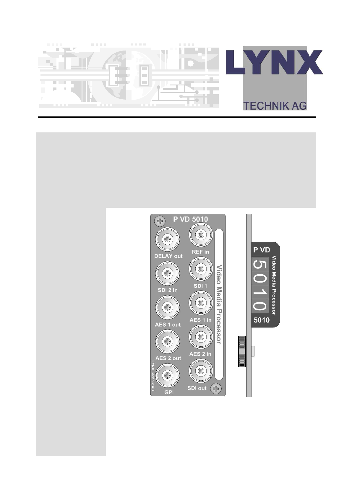
Reference Manual P VD 5010 B Version 1.1
Page 3
Warranty
LYNX Technik AG warrants that the product will be free from
defects in materials and workmanship for a period of two (2)
year from the date of shipment. If this product proves defective
during the warranty period, LYNX Technik AG at its option will
either repair the defective product without charge for parts and
labor, or will provide a replacement in exchange for the
defective product.
In order to obtain service under this warranty, customer must
notify LYNX Technik of the defect before expiration of the
warranty period and make suitable arrangements for the
performance of service. Customer shall be responsible for
packaging and shipping the defective product to the service
center designated by LYNX Technik, with shipping charges
prepaid. LYNX Technik shall pay for the return of the product to
the customer if the shipment is within the country which the LYNX
Technik service center is located. Customer shall be responsible
for payment of all shipping charges, duties, taxes and any other
charges for products returned to any other locations.
This warranty shall not apply to any defect, failure, or damage
caused by improper use or improper or inadequate
maintenance and care. LYNX Technik shall not be obligated to
furnish service under this warranty a) to repair damage resulting
from attempts by personnel other than LYNX Technik
representatives to install, repair or service the product; b) to
repair damage resulting from improper use or connection to
incompatible equipment; c) to repair any damage or
malfunction caused by the use of non LYNX Technik supplies; or
d) to service a product which has been modified or integrated
with other products when the effect of such modification or
integration increases the time or difficulty servicing the product.
THIS WARRANTY IS GIVEN BY LYNX TECHNIK WITH RESPECT TO THIS
PRODUCT IN LIEU OF ANY OTHER WARRANTIES, EXPRESS OR
IMPLIED. LYNX TECHNIK AND ITS VENDORS DISCLAIM ANY IMPLIED
WARRANTIES OF MERCHANTABILITY OR FITNESS FOR A PARTICULAR
PURPOSE. LYNX TECHNIK`S RESPONISIBILITY TO REPAIR AND
REPLACE DEFECTIVE PRODUCTS IS THE SOLE AND EXCLUSIVE
REMEDY PROVIDED TO THE CUSTOMER FOR BREACH OF THIS
WARRANTY. LYNX TECHNIK AND ITS VENDORS WILL NOT BE LIABLE
FOR ANY INDIRECT, SPECIAL, INCIDENTAL, OR CONSEQUENTAL
DAMAGES IRRESPECTIVE OF WHETHER LYNX TECHNIK OR THE
VENDOR HAS ADVANCE NOTICE OF THE POSSIBILITY OF SUCH
DAMAGES.