1.Loosen the lock screw (pos. 1) slightly.
2.Slowly move the clamp (pos. 2), and adjust the primary
air supply so that an optimal blue flame is obtained
(yellow or red indicates wrong setting).
3 Slowly tighten the lock screw (pos. 1).
4. after each replacement of the gas cylinder, the
adjustment of the primary air supply should be carried
out again.
Properly performed adjustment should ensure:
fast and correct burner ignition, re-ignition and flame
transmission gentle, explosion-free flame spread on all
flame openings in no more than 5 seconds,
slight flame recoil is allowed, however after 1 minute the
flame shall be stable, the flame does not go out and does
not withdraw towards the nozzle when the burner's heat
output is changed within the entire range of power
adjustment foreseen and when rotating the control knob
from maximum to minimum power at normal speed
(normal speed, i.e. rotating the control knob from
maximum to minimum power for approximately 1 s).
WARNING! Always clean the appliance after use Before
cleaning, make sure that the stove has cooled down -
there is a high risk of burns. Shut off the gas supply to
the appliance by turning off the valves. If you intend to
turn the appliance during cleaning, it is necessary to
disconnect the gas supply hose to the appliance.
(A). Turn off the appliance and disconnect the gas supply
hose before carrying out maintenance.
(B). Make sure the appliance has cooled down.
(C). To prevent damage to the appliance surface, clean it
regularly.
(D). Fat or food residues in the appliance may cause a
fire.
(E). Clean the appliance with a damp cloth.
(F). Use only neutral cleaning agents. Never use
abrasive agents, agents containing caustic, bleaching
substances or acids to clean the stove and avoid using
acidic or alkaline substances (lemon juice, vinegar, etc.).
(G). Do not clean the appliance with steam cleaners.
(H). After cleaning, the appliance must be dried.
3. Periodical service
After the warranty period, the appliance should be
subjected to periodic inspection at least once a year.
The periodic inspection should be carried out by persons
qualified in gas equipment repair and maintenance.
The minimum scope of the periodic inspection is control
of proper operation, maintenance of gas valves and gas
tightness test of the appliance.
Periodic inspections after the warranty period are not
included in the purchase cost of the appliance.
Properly prepared burner with reducer to be connected
to to the cylinder.
7 kW stove for: W4076, W40760, W4072, W4072_O
6,4 kW stove for: W4075
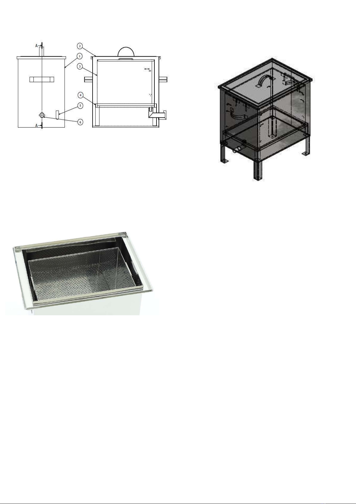
4. Melter operation principles
1. Fill the tank with water up to the level of the drain
pipe as in the picture (Fig.1). Fill in the water (take
special care not to burn yourself).
2. Fill the basket with frames or dry wax material.
3. Cover the device with the lid.
4. Place the stove under the unit so that the flame
heats the entire surface of the bottom of the unit.
5. Wait for the steam to rise and for the melted wax to
flow out.
6. When the wax has been melted check the water
level and top up if necessary.
7. Fill the basket with frames or dry wax material again.
8. Repeat steps 6 and 7 until the melting process is
completed.
9. When the process is finished turn off the burner
and close the gas bottle.
10. Clean the basket of debris and prepare it for the next
use.
11. This equipment is not intended for use by persons
(including children) with reduced physical, sensory or
mental capabilities, or lack of experience or
familiarity with the equipment, unless supervised or