LYSON MINIMA Series User manual

MANUAL
CASSETTE HONEY EXTRACTORS
MINIMA SERIES
720 –800 MM CONTROLLER HE –01
900 –1000 MM CONTROLLER HE –01M
Przedsiębiorstwo Pszczelarskie Tomasz Łysoń
Spółka z o.o. Spółka Komandytowa
34-125 Sułkowice, ul. Racławicka 162, Polska
www.lyson.com.pl, email; lyson@lyson.com.pl
tel. 33/875-99-40, 33/870-64-02
Siedziba Firmy Klecza Dolna 148, 34-124 Klecza Górna
2016

The following manual encompasses the devices
bearing the following codes:
HONEY EXTRACTORS WITH 4,6,8
CASSETTES AND 12V POWER SUPPLY
W2013MKN, W2014MKN, W2015MKN
LIST OF CONTENTS
1. General safety principles for using the
honey extractors
1.1. Safety principles
1.2. Electric safety
1.3. Operational safety
2. Honey extractor manual
2.1. General principles for preparing the honey
extractor for operation
2.2. Operating principles
3. Diagram for honey extractor
4. Characteristics for honey extractors
4.1. 4-cassette honey extractors
4.1.1. Technical parameters
4.2. 4-cassette honey extractors with 12V power
supply
4.2.1. Technical parameters of honey extractors
4.3. 6-cassette honey extractors with 12V power
supply
4.3.1. Technical parameters of honey extractors
4.4. Controllers in the MINIMA-series cassette
honey extractors with 12V power supply
4.4.1. Controllers for the honey extractors with
the diameter of 800 mm
4.4.2. Controller for the honey extractors with
the diameters 900 –1000 mm
5. Storing the honey extractors
6. Maintaining and cleaning the honey
extractors
7.1. Dismantling the basket in the MINIMA-series
cassette honey extractors with 12V power supply
7. Recycling
8. Guarantee

1. General safety principles for using the
honey extractors
Prior to device usage initiation, refer to the following
manual and act according the guidelines contained
therein. The manufacturer shall not be held accountable
for any damages caused by improper usage of the
device or its improper handling
1.1. Operating principles
1. The honey extractor is intended to centrifuge honey
from the frames.
2. The honey extractor must be washed thoroughly
prior to usage with water containing slight amount of
agents admissible to be used in cleaning the
devices coming into contact with food or by means
of a pressure washer, remember to protect the
electronic components and the bearings against
damping.!!!!
The honey extractors with 12V power supply must not be
connected to the mains from a rectifier as the risk of
controller damage may occur.
The said damage is not included into the
guarantee terms and conditions.
A feeder manufactured by ‘Łysoń’ company shall
remain the proper source of power”
1.2. Electric safety
1. If non-detachable power supply cable gets
damaged and must be replaced, it must be
performed at a guarantor’s or by a specialised repair
centre or by a qualified person in order to avoid any
threat. Do not operate the honey extractor when the
power supply cable is damaged .
2. Prior to plugging in the device to the mains, check
whether controller is switched off. 0/1 switch on the
controlling panel should be in “0” position.
3. Check the honey extractor and the power source for
nominal voltage compliance (battery or feeder
manufactured by “Łysoń” company)
4. Be careful while connecting the device to the mains.
Hands must be dry! The floor on which the extractor
has been placed must be dry!
5. While extracting, the lid of the honey extractor must
be closed ! it is strictly forbidden to open the lid
during extraction.
6. The honey extractor must not be dislocated during
extraction.
7. The engine and controller must be protected against
humidity (also during storage)
8. It is forbidden to pull the supply cable. The supply
cable must be kept away from heat sources, sharp
edges and it god technical state must be taken care
of.
1.3. Usage safety
1. The following equipment is not intended to be used
by persons with limited physical, sensory or mental
capabilities (including children) or persons
inexperienced or unfamiliar with that type of
equipment unless the usage occurs under
supervision or in line with the equipment operating
manual provided by safety supervising persons.
One must make sure that children do not play with
the honey extractor.
2. In case of any damage to the honey extractor, in
order to avoid the danger, the repairs may be
performed solely by a specialist servicing centre or a
qualified person.
3. It is forbidden to perform any maintenance works or
repairs when the device is in operation.
4. The device can be reactivated once the danger Has
been eliminated.
5. The device cannot be activated and stored with the
ambient temperature below 0º C.
Honey extractor cannot be activated when the
ambient temperature drops below 5º C. When the
honey extractor has been moved from a room with a
lower temperature to a room with a higher
temperature, prior to its activation one must wait
until the device has achieved the ambient
temperature.
It is forbidden to repair the device under operation
It is forbidden to remove the shields under operation
2. Honey extractor manual
2.1 general principles to prepare the honey
extractor for operation
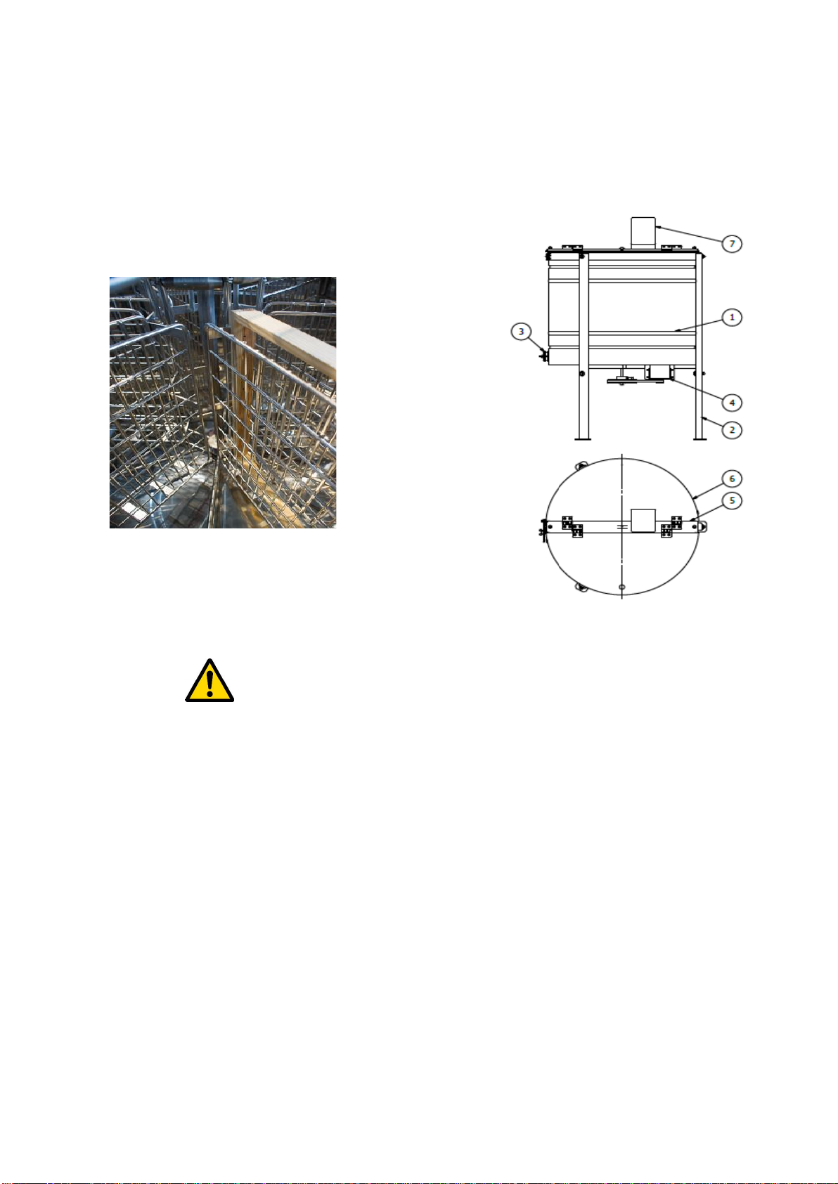
1. Place the honey extractor in the place specified
for the purpose.
2. Fix the honey extractor to the ground in order to
avoid its displacement during operation.
2.2 Operating principles
1. Honey extractor is intended to centrifuge the honey
from the frames.
2. Prior to extraction, the device must be washed
thoroughly in line with the guidelines contained in
the chapter Honey extractor maintenance.

3. While washing, special precautions must be taken to
prevent the motor and controller from damping
(they may be covered with water-proof material)
4. Rinse and dry the honey extractor thoroughly after
washing.
5. The arrangement of frames:
●The honey extractor must be properly selected
for the frame type.
●In case of cassette honey extractor, special
attention must be paid to a proper arrangement
of the frames . They must be placed inside the
cassette. (photo 1)
Photo 1. Proper arrangement of frames inside the
cassette honey extractor
NOTE!
Erroneous frame arrangements may cause the
damages excluded from the guarantee terms!
6. Prior to the honey extractor activation, one must:
●Make sure that the frames have been placed
properly inside the extractor basket, in order to
eliminate the risk of damages.
●Subsequently, connect the honey extractor to a
feeder, battery (12V) and go on to activate the
device in line with the manual
7. The first phase of extraction shall be performed
slowly in order to prevent the honeycombs from
breaking out. Special attention must be paid to the
so called “young frames”
8. Spinning basket shall not be blocked by the honey
accumulating inside the drum. If that is the case, the
extractor must be stopped to prevent its damaging.
Once the honey has drained to the containers,
spinning can be restarted.
9. Containers intended for the honey are to be placed
under the drain valves.
10. During spinning the drain valves must be opened in
order to let the honey drain freely.
Place of work
It should be well-lit and kept in order and cleanliness.
3. Diagram for the honey extractor
Legend:
1. Honey extractor drum
2. Honey extractor leg
3. Drain valve
4. Honey extractor motor
5. Fixing beam
6. Honey extractor lid
7. Honey extractor controller
4. Characteristics for honey extractors
A controller inside a plastic casing is mounted on the
beam. Honey extractors are dispatched with dismantled
controllers, which are placed inside the drum in order to
prevent damages during transportation.
4.2 4-cassette honey extractor with 12V power
supply
Such honey extractors are intended for stationary
apiaries as well as for portable ones. Power supply from
the batteries (12V) allows to centrifuge the honey without
the access to 230V mains.
The device is equipped with manual and automatic
operating mode.

4.2.1 Technical parameters
•The drum made of acid-resistant stainless steel
plate 0H18N9, properly reinforced and stiffened.
•Honey extractors are equipped with the bottom
made of steel plate thickness 0.6 mm. One
plastic discharge valve 6/4”
•The basket made of acid-resistant stainless steel
rods ø3 and ø5
•Cassettes are connected by special guides,
which eliminates the jamming, as well as the
springs which allow for the basket return to its
original position.
•the lid is made of plexiglass
•the 280W/24V motor in honey extractors with
diameters of 800 mm
•the 350W/24V motor in honey extractors with
diameters of 1000 mm
•honey extractor are equipped with a bottom drive
with a belt transmission
4.3. 6 or 8-cassette honey extractors with 12V
power supply
The honey extractors are intended for stationary and
mobile apiaries. 12V battery power supply allows to
centrifuge the honey without any access to the 230V
mains.
The honey extractors have a manual and an automatic
operating mode.
4.3.1. Technical parameters
•The drum has been made of acid-resistant
stainless steel plate 0H18N9, thickness 0.6 mm,
, properly reinforced and stiffened.
•The drum and the bottom made of 0.6 mm steel
plate, plastic valve 2 x 2”
•The basket made of acid-resistant, stainless steel
rods ø 3, ø 5 mm
•The cassettes are connected by special guides,
which eliminates the jamming, as well as by
springs which allow for the basket to return to its
original position.
•The lid made of plexiglass
•The 350W/24V motor in honey extractors with
diameters of 1000 mm
4.4. Controllers for 4-cassette honey
extractors with 12V power supply
4.4.1. Controller for honey extractors with
diameters of 800 MM and 12V power supply
(CONTROLLER –HE-01)
The Controller is equipped with 0/1 switch to activate and
deactivate the honey extractor, the fuse is located under
the 0/1 switch (15A fuse)
The control panel is equipped with the navigating buttons
„PLUS” , „MINUS” and the „ON/OFF” button
Controller description:
Controller has 12 programmes.
•Two manual programmes: one to the right, one to
the left
MANUAL MODE –TO THE RIGHT
MANUAL MODE –TO THE LEFT
•programme P-AUTO, which allows to
configure independently user’s own
spinning cycle

AUTOMATIC MODE
•and 9 factory-set programmes - (only he honey
extractors with diameters (720 Ø 800) .
AUTOMATIC MODE
FROM „1-AUTO” TO „9 -AUTO”
Activation and programme selection
Prior to connecting the honey extractor to the mains,
make sure whether the 0/1 switch on the controller
casing remains in “0” position.
Subsequently, the 0/1 switch shall be set from „0”
position to „1” position.
In order to activate the manual programmes or one of the
automatic programmes, select a required programme by
means of PLUS or MINUS buttons and subsequently
press the ON/OFF button.
In manual programmes, by pressing the PLUS or MINUS
buttons , we increase or decrease the rotating speed of
the basket.
Stop the basket by ON/OFF button.
•Programming the „P-AUTO” mode
Process regulator named HE-01 allows to introduce one
user’s own technological cycle “P-AUTO”. Programming
the user’s own cycles occurs in the configuration and
programming menu.
In order to program user’s own technological cycle, one
must enter the aforementioned configuration and
programming mode. In order to do this, deactivate the
honey extractor by 0/1 switch on the controller casing
and wait for a few seconds. Later, press the 0/1 switch
again.
Entering the configuration and programming
mode.
The illustration above demonstrates how to enter the
programming cycle.
While the controller gets activated, i.e. when the name of
the manufacturer and the device type are displayed,
press and hold both buttons PLUS and MINUS until the
Prog message, i.e. programming, has appeared on the
screen
Programming the “P-AUTO” cycle consists of four steps
, equal as far as their durations are concerned.
Additionally, steps 1 and 2 as well as 4 and 5 are
characterized by identical spinning velocity.
The first parameter:
„t” – it is the total operating time for the honey extractor
expressed in minutes.
The parameter is set by means of PLUS and MINUS
buttons.
Programming –setting up the total time for the cycle
duration (from 3 to 15 minutes).
Duration of each of the four steps remains the total time
of the spinning cycle divided into 4 –e.g. for the set up
t=4 minutes, each step lasts one minute.
The settings are confirmed by pressing the ON/OFF
button
The second parameter:
„s1”–i.e. the spinning velocity of the extractor basket
during step 1 and 2.
The parameter is set up by pressing the PLUS and
MINUS buttons
The settings are confirmed by pressing the ON/OFF
button. Without the breaks between the cycles
t=4m
ON/OFF

Programming –setting from 25% to 100%.
Setting 100% is displayed as ''max''.
The third parameter:
„s2”, i.e. spinning velocity of the extractor basket durian
step 3 and 4.
The parameter is set up by pressing the PLUS and
MINUS buttons
The settings are confirmed by pressing the ON/OFF
button
Programming –setting from 25% to 100%.
Setting 100% is displayed as ''max''.
The last, fourth parameter:
„d” –acceleration time (range 5-15), optimum
acceleration remains 15.
The parameter is set up by pressing the PLUS and MINUS
buttons
The settings are confirmed by pressing the ON/OFF button
Programming –defining the dynamics of the motor
acceleration (settings from 5 to 25).
5 –motor accelerates slowly,
25 –motor accelerates quickly.
The setting entered has an impact over the motor
operational dynamics regardless of the selected cycle
and operational mode.
Direct ion right = P S1
Direction left = L
Direction left = L S2
Direction right = P
Message ''O'' signals the end of programming, after
which the controller gets restarted. The honey extractor
is ready for operation.
Pre-defined automatic cycles.
HE-01 controller possesses 9 factory-set spinning
cycles.
Parameters for the individual cycles have been collected
in the table below. For the programmable cycle (P-
AUTO) the table specifies the default values.
Cycle
Stage/cycle duration
Speed for
steps
1 and 2
Speed for
steps 3
and 4
1-Auto
3min/ (45sec)
40%
85%
2-Auto
3min 30sec/(52.5sec)
40%
85%
3-Auto
4min/(60sec)
50%
90%
4-Auto
4min 30sec/(67.5sec)
50%
90%
5-Auto
5min/(75sec)
55%
95%
6-Auto
5min 30sec/(82.5sec)
55%
95%
7-Auto
9min/(135sec)
60%
100%
8-Auto
9min 45sec/(146.2sec)
60%
100%
9-Auto
10min 30sec/(157.5sec)
60%
100%
P-Auto
4minuty /(60sec)
55%
100%
4.4.2. controller HE-01 for honey extractors
with diameters of 1000 mm and 12V power
supply
The controller is equipped with “0/1” switch serving for
activation and deactivation of the honey extractor as
well as 15Afuses.
The control panel is equipped with navigating buttons
PLUS and MINUS and the ON/OFF button.
Description of the controller:
The controller has three programmes:
•Two manual programmes: one to the right and
one to the left
MANUAL MODE –TO THE RIGHT
s1=55%
ON/OFF
s2=max
ON/OFF
d=15
ON/OFF

Manual Mode –to the left
•program P-AUTO. which allows a user to
configure their own independent spinning cycle
MANUAL MODE
•Activation and program selection
•Prior to connecting the honey extractor to the mains.
make sure whether the „0/1” switch on the
controller casing remains in „0” position. .
•Next. the „0/1” switch shall be moved from „0” to „1”
position.
•In order to activate the manual programs or one of
the automatic programs. select a required program
by means of PLUS or MINUS buttons
•Next. press the ON/OFF button
•In manual programs. by pressing PLUS or MINUS
buttons. the velocity of basket spinning gets
increased or decreased.
•Stop the basket by pressing the ON/OFF button.
•Programming the „P-AUTO” mode
Process regulator named HE-01 allows to introduce
one user’s own technological cycle “P-AUTO”.
Programming the user’s own cycles occurs in the
configuration and programming menu.
In order to program user’s own technological cycle.
one must enter the aforementioned configuration
and programming mode. In order to do this.
deactivate the honey extractor by 0/1 switch on the
controller casing and wait for a few seconds. Later.
press the 0/1 switch again
Entering the configuration and programming
mode.
The illustration above demonstrates how to enter the
programming cycle.
While the controller gets activated. i.e. when the name of
the manufacturer and the device type are displayed.
press and hold both buttons PLUS and MINUS until the
Prog message. i.e. programming. has appeared on the
screen
Programming the “P-AUTO” cycle consists of four steps
. equal as far as their durations are concerned.
Additionally. steps 1 and 2 as well as 3 and 4 are
characterized by identical spinning velocity
The first parameter:
„t” – it is the total operating time for the honey extractor
expressed in minutes.
The parameter is set by means of PLUS and MINUS
buttons”
Programming –setting up the total time for the cycle
duration (from 3 to 15 minutes).
Duration of each of the four steps remains the total time
of the spinning cycle divided into 4 –e.g. for the set up
t=4 minutes. each step lasts one minute.
The settings are confirmed by pressing the ON/OFF
button
The second parameter:
„s1”–i.e. the spinning velocity of the extractor basket
during step 1 and 2.
The parameter is set up by pressing the PLUS and
MINUS buttons
The settings are confirmed by pressing the ON/OFF
button. Without the breaks between the cycles
Programming –setting from 25% to 100%.
Setting 100% is displayed as ''max''.
t=4m
ON/OFF
s1=55%
ON/OFF

The third parameter:
„s2”. i.e. spinning velocity of the extractor basket durian
step 3 and 4.
The parameter is set up by pressing the PLUS and
MINUS buttons
The settings are confirmed by pressing the ON/OFF
button
Programming –setting from 25% to 100%.
Setting 100% is displayed as ''max''.
The last. fourth parameter:
„d” –acceleration time (range 5-15). optimum
acceleration remains 15.
The parameter is set up by pressing the PLUS and MINUS
buttons
The settings are confirmed by pressing the ON/OFF button
Programming –defining the dynamics of the motor
acceleration (settings from 5 to 25).
5 –motor accelerates slowly.
25 –motor accelerates quickly
The setting entered has an impact over the motor
operational dynamics regardless of the selected cycle
and operational mode.
Direct ion right = P S1
Direction left = L
Direction left = L S2
Direction right = P
Message ''O'' signals the end of programming. after
which the controller gets restarted. The honey extractor
is ready for operation.
•Configuration menu –fine tuning
In order to enter the configuration menu of the controller
ne must press and hold MINUS and ON/OFF button at
the same time during the controller’s start-up. i.e. when
the manufacturer’s name and device type are displayed.
until the message Config has appeared (controller’s
configuration menu)
Controller’s configuration menu allows to tune in the
driving system operations precisely to the loads –
characteristic for a given extractor type (Ø 900 -Ø 1200 )
Menu allows to program 6 parameters specified below.
•Parameter b1 (setting 20s –180s. default 50s) First
breaking time of the cycle. the time needed to make
a return while breaking from S1 speed (lower speed
defined for steps 1 and 2).
•Parameter b2 (setting 20s –180s. default 50s)
Second breaking time of the cycle. the time needed
to make a return while breaking from S2 speed
(higher speed defined for steps 3 and 4) and to stop
the extractor basket once step 4 has been finished.
•Parameter bm (setting 1-10. default 8) Calibrating
the breaking time. regulation of the time needed to
stop the extractor basket during operational stop in
an automatic or a manual mode
•Parameter ms (setting 15 –25. default 25) Limiting
the
Maximum rotational speed of the motor (lowering
the acquired spinning velocities).
•Parameter d (setting 5 –25. default 25)
Configuration of the motor operational dynamics
(acceleration Speer).
•Parameter fs (setting 1s –20s. default 10s)
Configuration of the speed forcing time durian the
motor start-up (influences the capability of the
extractor to “stack the frames”).
5. Storing the honey extractors
Once the honey harvesting has terminated the
device is to be washed thoroughly.
Prior to the honey extractor start-up. in case when it
has been transferred from a room with a lower
ambient temperature to a room with a higher one .
one must wait until the device has reached the
ambient temperature.
The device is to be stored in dry rooms with the
temperature above 0º C.
Before every season. an additional technical
inspection must be performed and n case when any
defects have been detected . a service centre must
be contacted
.
6. Honey extractor maintenance and cleaning
s2=max
ON/OFF
d=15
ON/OFF

IMPORTANT!
Prior to the maintenance. disconnect the honey
extractor from the source of power supply (battery or
feeder made by „Łysoń” company).
After honey harvesting time honey extractor shall be
washed thoroughly with hot water containing slight
quantities of agents accepted to be used in devices
intended to come into contact with food or by means of a
pressure washer. Be careful during the washing and
prevent dumping the honey extractor engine or controller
( they may be covered with water-resistant materials)
While washing. the bearings placed under the drum
cannot be flooded. Therefore. the orifice through which
the basket axis goes must be covered inside the drum.
After washing. the honey extractor must be rinsed with
pure water and dried.
6.2. Dismantling the basket in 4 and 6-
cassette honey extractors with 12V power supply
•Loosen and remove a V-belt
•Loosen the bolt on the pulley
•Unscrew and remove the upper beam with the
lids
•Remove the basket
7. Recycling
Worn-out product must be removed as waste only
within selective waste collection organised by the
Network of Communal Electric and Electronic Waste
Collecting Points. A customer is entitled to return the
used equipment to the electrical equipment distributor
network. at least free of charge and directly. if the
device to be returned is of proper type and serves the
same purpose as the newly purchased device
8. Guarantee
Product purchased from “Łysoń’ company are
encompassed by the manufacturer’s guarantee.
The guarantee duration equals 2 years .
A receipt or a VAT invoice is issued for each product
purchased
.

INSTRUKCJA OBSŁUGI
MIODAREK KASETOWYCH MINIMA
720 –800 MM STEROWANIE HE –01
900 –1000 MM STEROWANIE HE –01M
Przedsiębiorstwo Pszczelarskie Tomasz Łysoń
Spółka z o.o. Spółka Komandytowa
34-125 Sułkowice, ul. Racławicka 162, Polska
tel. 33/875-99-40, 33/870-64-02
Siedziba Firmy Klecza Dolna 148, 34-124 Klecza Górna
2016

Instrukcja obejmuje miodarki o kodach:
MIODARKI 4,6,8 KASETOWE Z ZASILANIEM 12V
W2013MKN, W2014MKN, W2015MKN
SPIS TREŚCI
1. Ogólne zasady bezpieczeństwa użytkowania miodarki
1.1. Zasady użytkowania
1.2. Bezpieczeństwo elektryczne
1.3. Bezpieczeństwo użytkowania
2. Instrukcja użytkowania miodarki
2.1. Ogólne zasady przygotowania miodarki do pracy
2.2. Zasady użytkowania
3. Schemat miodarki
4. Charakterystyka miodarek
4.1. Miodarki 4 kasetowe
4.1.1. Parametry techniczne
4.2. Miodarki 4 kasetowe z zasilaniem 12V
4.2.1. Parametry techniczne miodarek
4.3. Miodarki 6 kasetowe z zasilaniem 12V
4.3.1. Parametry techniczne miodarek
4.4. Sterowania w miodarkach MINMAkasetowych 12V
4.4.1. Sterowanie miodarek o średnicy 800 mm
4.4.2. Sterowanie dla miodarek o średnicy 900 – 1000 mm
5. Przechowywanie miodarek
6. Konserwacja i czyszczenie miodarki
7.1. Demontaż kosza w miodarkach MINMA kasetowych 12V
7. Utylizacja
8. Gwarancja

1. Ogólne zasady bezpieczeństwa
użytkowania miodarki
Przed rozpoczęciem użytkowania urządzenia należy
przeczytać instrukcję użytkowania i postępować według
wskazówek w niej zawartych. Producent nie odpowiada
za szkody spowodowane użytkowaniem urządzenia
niezgodnie z jego przeznaczeniem lub niewłaściwą jego
obsługą.
1.1. Zasady użytkowania
1. Miodarka przeznaczona jest do odwirowywania miodu
z ramek.
2. Miodarkę przed wirowaniem należy dokładnie umyć
gorącą wodą z niewielką ilością preparatów
dopuszczonych do mycia urządzeń przeznaczonych do
kontaktu z żywnością, lub za pomocą myjki ciśnieniowej,
pamiętając o zabezpieczeniu elementów elektronicznych
i łożysk przed zamoczeniem !!!
Miodarek ze sterowaniem 12V zabrania podłączać do
źródła zasilania z prostownika ponieważ może wystąpić
ryzyko uszkodzenie sterowania.
Uszkodzenie to nie podlega gwarancji.
Właściwym źródłem zasilania jest akumulator lub
zasilacz Firmy „Łysoń”
1.2. Bezpieczeństwo elektryczne
1. Jeżeli przewód zasilający nieodłączany lub przewód
łączeniowy ulegnie uszkodzeniu i trzeba go
wymienić, to czynność ta powinna być wykonana u
gwaranta lub przez specjalistyczny zakład
naprawczy albo przez wykwalifikowaną osobę w
celu uniknięcia zagrożenia.
2. Nie używać miodarki, gdy przewód zasilający lub
łączeniowy jest uszkodzony.
3. Przed włączeniem urządzenia do zasilania należy
upewnić się, że sterowanie jest wyłączone.
Wyłącznik „0/1” na panelu sterowania powinien
znajdować się w pozycji 0.
4. Należy upewnić się, czy napięcie nominalne
miodarki i źródła zasilania są zgodne (akumulator
lub zasilacz Firmy Łysoń).
5. Podczas podłączania do zasilania należy zachować
ostrożność. Ręce muszą być suche! Podłoże, na
którym stoi wirówka powinno być suche!
6. Pokrywa miodarki podczas wirowania musi być
zamknięta! Zabrania się otwierania pokrywy
miodarki podczas wirowania.
7. Nie należy przestawiać miodarki podczas wirowania.
8. Należy chronić silnik oraz sterowanie przed wilgocią;
(również podczas przechowywania)
9. Zabrania się ciągnąć za przewód zasilający.
Przewód zasilający należy trzymać z dala od źródeł
ciepła, ostrych krawędzi oraz dbać o jego dobry
stan.
1.3. Bezpieczeństwo użytkowania
1. Niniejszy sprzęt nie jest przeznaczony do
użytkowania przez osoby (w tym dzieci) o
ograniczonej zdolności fizycznej, czuciowej lub
psychicznej lub osoby nie mające doświadczenia lub
znajomości sprzętu, chyba, że odbywa się to pod
nadzorem lub zgodnie z instrukcją użytkowania
sprzętu, przekazanej przez osoby odpowiadające za
ich bezpieczeństwo. Należy zwracać uwagę na
dzieci, aby nie bawiły się miodarką.
2. W przypadku uszkodzenia miodarki, w celu
uniknięcia zagrożenia, naprawę może
przeprowadzić tylko specjalistyczny zakład
naprawczy albo wykwalifikowana osoba.
3. Zabrania się prowadzić jakichkolwiek prac
konserwacyjnych podczas pracy urządzenia.
4. Ponowne uruchomienie miodarki może nastąpić po
wyeliminowaniu zagrożenia.
5. Urządzenia nie wolno włączać i przechowywać przy
temperaturze poniżej 0º C. Miodarki nie należy
włączać, gdy temperatura otoczenia jest niższa niż
5º C. Przed uruchomieniem miodarki, w przypadku
gdy została ona przeniesiona z pomieszczenia o
niższej temperaturze do pomieszczenia o wyższej
temperaturze, należy odczekać aż osiągnie ona
temperaturę otoczenia.
Zakaz naprawiania urządzenia w ruchu
Zakaz zdejmowania osłon podczas pracy urządzenia
2. Instrukcja użytkowania miodarki
2.1 Ogólne zasady przygotowania miodarki do
pracy
1. Ustawić miodarkę w miejscu do tego celu
wyznaczonym.
2. Przymocować miodarkę do podłoża, celem
uniknięcia jej przestawienia podczas wirowania.
2.2 Zasady użytkowania
1. Miodarka przeznaczona jest do odwirowywania
miodu z ramek.
2. Miodarkę przed wirowaniem należy dokładnie umyć
zgodnie z zasadami zawartymi w rozdziale
„Konserwacja Miodarki”

3. Podczas mycia zachować szczególną ostrożność,
aby nie dopuścić do zawilgocenia silnika, sterowania
miodarki (na czas mycia można je okryć
nieprzemakalnym materiałem)
4. Po umyciu należy dokładnie spłukać i osuszyć
miodarkę.
5. Ułożenie ramek:
●Miodarka powinna być odpowiedniego dobrana
do typu ramek.
●W miodarce kasetowej zwracamy szczególną
uwagę na prawidłowe ułożenie ramek, które
powinny mieścić się w kasecie. (fot.1)
fot.1 Prawidłowe ułożenie ramek w miodarce kasetowej
Uwaga!
Błędy w ułożeniu ramek mogą spowodować
uszkodzenia, które nie podlegają gwarancji!
6. Przed przystąpieniem do uruchomienia miodarki,
należy:
●upewnić się, że ramki zostały prawidłowo
umieszczone w koszu miodarki, aby
wyeliminować ryzyko uszkodzenia.
●następnie podpiąć miodarkę do zasilacza,
akumulatora (12V) i przystąpić do włączenia
miodarki zgodnie z instrukcją sterowania
miodarki
7. Pierwsza faza wirowania powinna odbywać się
powoli, aby zapobiec ewentualnemu wyłamywaniu
się plastrów. Szczególną uwagę należy zwrócić na
tzw. “młode ramki”.
8. Wirujący kosz nie powinien być blokowany przez
zalegający w bębnie miód, jeżeli nastąpi taka
sytuacja należy zatrzymać miodarkę, aby nie
dopuścić do jej uszkodzenia. Po spłynięciu miodu do
pojemników można wznowić wirowanie.
9. Pod zawory spustowe należy podstawić zbiorniki
przeznaczone na miód.
10. Podczas wirowania zawory spustowe powinny być
otwarte, aby odwirowany miód mógł swobodnie
spływać.
Miejsce pracy
Powinno być oświetlone oraz utrzymane w należytej
czystości.
3.Schemat miodarki
Legenda:
1. Bęben miodarki
2. Noga miodarki
3. Zawór spustowy
4. Silnik miodarki
5. Belka mocująca
6. Pokrywa miodarki
7. Sterowanie miodarki
4. Charakterystyka miodarek
Sterownik w obudowie plastikowej mocuje się na belce
miodarki. Miodarki wysyłane są z zdemontowanym
sterowaniem, umieszczonym w bębnie miodarki, aby
zapobiec uszkodzeniom w czasie transportu
4.2. Miodarki 4 kasetowe z zasilaniem 12V
Miodarki przeznaczone są zarówno dla pasiek
stacjonarnych jak również wędrownych. Zasilanie
akumulatorowe (12 V) pozwala odwirowanie miodu bez
dostępu do sieci 230V
Miodarki te posiadają możliwość pracy w trybie ręcznym
i automatycznym

4.2.1 Parametry techniczne
•bęben wykonany z blachy nierdzewnej
kwasoodpornej 0H18N9, odpowiednio wzmocniony i
usztywniony
•miodarki mają bęben oraz dno wykonane z
blachy o grubości 0,6mm. Jeden spust plastikowy 6/4”
•kosz wykonany z prętów nierdzewnych
kwasoodpornych ø3 i ø5
•kasety połączone są ze sobą specjalnymi
prowadnikami, które wykluczają się zakleszczanie się
kaset oraz sprężynami, które pozwalają na powrót do
położenia wyjściowego
•pokrywa wykonana jest z metapleksu
•silnik 280W/24V w miodarkach o średnicy
800mm
•silnik 350W/24V w miodarkach o średnicy
1000mm
•miodarki posiadają napęd dolny z przekładnią
pasową
4.3. Miodarki 6 - 8 kasetowe z zasilaniem 12V
Miodarki przeznaczone są zarówno dla pasiek
stacjonarnych jak również wędrownych. Zasilanie
akumulatorowe (12 V) pozwala odwirowanie miodu bez
dostępu do sieci 230V
Miodarki te posiadają możliwość pracy w trybie ręcznym
i automatycznym
4.3.1. Parametry techniczne
•bęben wykonanej z blachy nierdzewnej
kwasoodpornej 0H18N9, odpowiednio
wzmocniony i usztywniony
•bęben oraz dno wykonane są z blachy o grubości
0,6mm, zawór plastikowy 2 x 2”
•kosz wykonany z prętów nierdzewnych
kwasoodpornych ø 3, ø 5 mm
•kasety połączone są ze sobą specjalnymi
prowadnikami, które wykluczają się
zakleszczanie się kaset oraz sprężynami, które
pozwalają na powrót do położenia wyjściowego
•pokrywa wykonana jest z metapleksu
•silnik 350W/24V w miodarkach o średnicy 1000
mm
4.4. Sterowania w miodarkach 4 kasetowych
12V
4.4.1. Sterowanie Miodarek o Średnicy
800 MM Z Napięciem 12V
(STEROWNIK –HE-01)
Sterownik posiada wyłącznik 0/1 służący do włączenia i
wyłączenia miodarki, bezpiecznik znajdujące się pod
wyłącznikiem 0/1 (bezpiecznik 15A).
Panel sterowania wyposażony jest w przyciski
nawigacyjne „PLUS” , „MINUS” oraz w przycisk
„ON/OFF”
Opis Sterownika:
Sterowanie posiada 12 programów.
•Dwa programy ręczne: jeden w prawo, drugi w lewo
TRYB RĘCZNY W PRAWO
TRYB RĘCZNY W LEWO

•program P-AUTO, który umożliwia
samodzielne skonfigurowanie własnego
cyklu wirowania
TRYB AUTOMATYCZNY
•oraz 9 programów ustawionych fabrycznie - (tylko
miodarki o średnicy (720 Ø 800) .
TRYB AUTOMATYCZNY
OD „1-AUTO” DO „9 -AUTO”
Włączanie i wybór programu
Przed włączeniem miodarki do zasilania upewniamy się
czy wyłącznik „0/1” na obudowie sterownika znajduje się
w pozycji „0”.
Następnie wyłącznik „0/1” przestawiamy z pozycji „0” na
poz. „1”.
Aby uruchomić programy ręczne lub jeden z programów
automatycznych wybieramy żądany program za pomocą
przycisków „PLUS” lub „MINUS”
a następnie naciskamy przycisk „ON/OFF”
W programach ręcznych poprzez naciskanie przycisków
„PLUS” lub „MINUS” zwiększamy lub zmniejszamy
prędkość z jaką obraca się kosz.
Przyciskiem „ON/OFF” zatrzymujemy kosz.
•Programowanie Trybu
„P-AUTO”
Regulator procesowy HE-01 umożliwia wprowadzenie
jednego własnego cyklu technologicznego „P-AUTO”.
Programowanie własnych cykli odbywa się w menu
konfiguracji i programowania.
W celu zaprogramowania własnego cyklu
technologicznego należy zatem wejść we wspomniany
tryb konfiguracji i programowania. W tym celu
wyłączamy miodarkę wyłącznikiem „0/1” na obudowie
sterownika i odczekujemy kilka sekund, później
ponownie włączamy przycisk „0/1”.
Wejście w tryb konfiguracji i programowania.
Sposób wejścia w tryb programowania ilustruje
powyższy rysunek.
W czasie uruchamiania się sterownika czyli wyświetlania
nazwy producenta i typu urządzenia należy
równocześnie nacisnąć i przytrzymać przyciski „PLUS”
lub „MINUS” aż do momentu gdy na wyświetlaczu
pojawieniu się napis ''Prog.'' - czyli programowanie.
Programowanie cyklu „P-AUTO” składa się z czterech
identycznych pod względem czasu trwania kroków.
Dodatkowo, kroki 1 i 2 oraz kroki 3 i 4 charakteryzują się
identyczną prędkością wirowania.
Pierwszy parametr:
„t” -jest to całkowity czas pracy miodarki wyrażony w
minutach.
Parametr ten ustawiamy za pomocą przycisków „PLUS”
lub „MINUS”
Programowanie –ustawienie łącznego czasu trwania
cyklu (ustawiamy od 3 do 15 minut).
Czas trwania każdego z czterech kroków to łączny czas
trwania cyklu wirowania podzielony przez cztery –
przykładowo dla ustawienia t = 4 minuty, każdy krok trwa
jedną minutę.
Ustawienie zatwierdzamy przyciskiem „ON/OFF”.
Drugi parametr:
t=4m
ON/OFF

„s1”- czyli prędkość wirowania kosza miodarki w
1 i 2 kroku.
Parametr ten ustawiamy za pomocą przycisków „PLUS”
lub „MINUS”
Ustawienie zatwierdzamy przyciskiem „ON/OFF”. Bez
przerw między cyklami.
Programowanie - ustawienie od 25% do 100%.
Ustawienie 100% wyświetlane jest jako ''max''.
Trzeci parametr:
„s2”czyli prędkość wirowania kosza miodarki podczas 3
i 4 kroku
Parametr ten ustawiamy za pomocą przycisków „PLUS”
lub „MINUS”
Ustawienie zatwierdzamy przyciskiem „ON/OFF”.
Programowanie –ustawienie od 25% do 100%.
Ustawienie 100% wyświetlane jest jako ''max''.
Ostatni czwarty parametr:
„d” - czas przyspieszenia (zakres 5-25) optymalne
przyspieszenie to 15 .
Parametr ten ustawiamy za pomocą przycisków „PLUS”
lub „MINUS”
Ustawienie zatwierdzamy przyciskiem „ON/OFF”.
Programowanie –definiowanie dynamiki przyspieszania
silnika (ustawienia od 5 do 25).
5 –silnik przyspiesza wolno,
25 –silnik przyspiesza szybko.
Wprowadzone ustawienie ma wpływ na dynamikę pracy
silnika niezależnie od wybranego cyklu i trybu pracy.
Kierunek prawo = P S1
Kierunek lewo = L
Kierunek lewo = L
S2
Kierunek prawo = P
Komunikat ''O'' sygnalizuje zakończenie programowania,
po którym następuje restart sterownika. Miodarka jest
gotowa do pracy.
Predefiniowane cykle automatyczne
Sterownik HE-01 posiada 9 ustawionych fabrycznie cykli
wirowania. Parametry poszczególnych cykli zebrano w
poniższej tabeli. Dla cyklu programowalnego (P-AUTO)
w tabeli podano wartości domyślne.
Cykl
Czas trwania cyklu kroku
Prędkość
kroków
1 oraz 2
Prędkość
kroków
3 oraz 4
1-Auto
3min/ (45sec)
40%
85%
2-Auto
3min 30sec/(52,5sec)
40%
85%
3-Auto
4min/(60sec)
50%
90%
4-Auto
4min 30sec/(67,5sec)
50%
90%
5-Auto
5min/(75sec)
55%
95%
6-Auto
5min 30sec/(82,5sec)
55%
95%
7-Auto
9min/(135sec)
60%
100%
8-Auto
9min 45sec/(146,2sec)
60%
100%
9-Auto
10min 30sec/(157,5sec)
60%
100%
P-Auto
4minuty /(60sec)
55%
100%
4.4.2. Sterownik HE-01M dla miodarek o
średnicy 1000 mm Z NAPIĘCIEM 12V
Sterownik posiada wyłącznik „0/1” służący do włączenia i
wyłączenia miodarki oraz Bezpieczniki 15A
Panel sterowania wyposażony jest w przyciski
nawigacyjne „PLUS” , „MINUS” oraz w przycisk
„ON/OFF”
Opis Sterownika:
Sterowanie posiada 3 programy:
•Dwa programy ręczne: jeden w prawo, drugi w
lewo
s1=55%
ON/OFF
s2=max
ON/OFF
d=15
ON/OFF

TRYB RĘCZNY W PRAWO
TRYB RĘCZNY W LEWO
•program P-AUTO, który umożliwia samodzielne
skonfigurowanie własnego cyklu wirowania
TRYB AUTOMATYCZNY
•Włączanie i wybór programu
•Przed włączeniem miodarki do zasilania upewniamy
się czy wyłącznik „0/1”na obudowie sterownika
znajduje się
w pozycji „0”.
•Następnie wyłącznik „0/1” przestawiamy z pozycji
„0” na poz. „1”.
•Aby uruchomić programy ręczne lub jeden z
programów automatycznych wybieramy żądany
program za pomocą przycisków „PLUS” lub
„MINUS”
•następnie naciskamy przycisk „ON/OFF”
•W programach ręcznych poprzez naciskanie
przycisków „PLUS” lub „MINUS” zwiększamy lub
zmniejszamy prędkość z jaką obraca się kosz.
•Przyciskiem „ON/OFF” zatrzymujemy kosz.
•Programowanie Trybu „P-AUTO”
Regulator procesowy HE-01 umożliwia wprowadzenie
jednego własnego cyklu technologicznego „P-AUTO”.
Programowanie własnych cykli odbywa się w menu
konfiguracji i programowania. W celu zaprogramowania
własnego cyklu technologicznego należy zatem wejść we
wspomniany tryb konfiguracji i programowania. W tym celu
wyłączamy miodarkę wyłącznikiem „0/1” na obudowie
sterownika i odczekujemy kilka sekund, później ponownie
włączamy wyłącznik „0/1”.
Wejście w tryb konfiguracji i programowania.
Sposób wejścia w tryb programowania ilustruje powyższy
rysunek.
W czasie uruchamiania się sterownika czyli wyświetlania
nazwy producenta i typu urządzenia należy
równocześnie nacisnąć i przytrzymać przyciski „PLUS”
lub „MINUS” aż do momentu gdy na wyświetlaczu
pojawieniu się napis ''Prog.'' - czyli programowanie.
Programowanie cyklu „P-AUTO” składa się z czterech
identycznych pod względem czas u trwania kroków.
Dodatkowo, kroki 1 i 2 oraz kroki 3 i 4 charakteryzują się
identyczną prędkością wirowania.
Pierwszy parametr:
„t” -jest to całkowity czas pracy miodarki wyrażony w
minutach.
Parametr ten ustawiamy za pomocą przycisków „PLUS”
lub „MINUS”
Programowanie –ustawienie łącznego czasu trwania
cyklu (ustawiamy od 3 do 15 minut).
Czas trwania każdego z czterech kroków to łączny czas
trwania cyklu wirowania podzielony przez cztery –
przykładowo dla ustawienia t = 4 minuty, każdy krok trwa
jedną minutę.
Ustawienie zatwierdzamy przyciskiem „ON/OFF”.
Drugi parametr:
„s1” - czyli prędkość wirowania kosza miodarki w
1 i 2 kroku.
Parametr ten ustawiamy za pomocą przycisków „PLUS”
lub „MINUS”
Ustawienie zatwierdzamy przyciskiem „ON/OFF”.
s1=55%
ON/OFF
t=4m
ON/OFF

Programowanie - ustawienie od 25% do 100%.
Ustawienie 100% wyświetlane jest jako ''max''.
Trzeci parametr:
„s2„ czyli prędkość wirowania kosza miodarki podczas 3
i 4 kroku
Parametr ten ustawiamy za pomocą przycisków „PLUS”
lub „MINUS”
Ustawienie zatwierdzamy przyciskiem „ON/OFF”.
Programowanie –ustawienie od 25% do 100%.
Ustawienie 100% wyświetlane jest jako ''max''.
Ostatni czwarty parametr:
„d” - czas przyspieszenia (zakres 5-25) optymalne
przyspieszenie to 15.
Parametr ten ustawiamy za pomocą przycisków „PLUS”
lub „MINUS”
Ustawienie zatwierdzamy przyciskiem „ON/OFF”.
Programowanie –definiowanie dynamiki przyspieszania
silnika (ustawienia od 5 do 25).
5 –silnik przyspiesza wolno,
25 –silnik przyspiesza szybko.
Wprowadzone ustawienie ma wpływ na dynamikę pracy
silnika niezależnie od wybranego cyklu i trybu pracy.
Kierunek prawo = P
S1
Kierunek lewo = L
Kierunek lewo = L S2
Kierunek prawo = P
Komunikat ''O'' sygnalizuje zakończenie programowania,
po którym następuje restart sterownika. Miodarka jest
gotowa do pracy.
•Menu Konfiguracyjne –dostrojenie
Sposób wejścia w tryb konfiguracji sterownika odbywa
się w czasie uruchamiania się sterownika czyli
wyświetlania producenta i typu urządzenia, należy
równocześnie nacisnąć i przytrzymać przyciski „MINUS”
oraz „ON/OFF” aż pojawi się napis Config (menu
konfiguracyjne sterownika)
Menu konfiguracyjne sterownika umożliwia precyzyjne
dostrojenie pracy układu
napędowego silnika do obciążeń – charakterystycznych
dla danego typu miodarki (Ø 900 -Ø 1200 )
Menu umożliwia zaprogramowanie sześciu
zamieszczonych poniżej parametrów.
•Parametr b1 (nastawa 20s –180s, domyślnie 50s)
Pierwszy czas hamowania cyklu, czas potrzebny do
wykonania nawrotu hamując z prędkości S1
(mniejszej prędkości definiowanej dla kroków 1 oraz
2).
•Parametr b2 (nastawa 20s –180s, domyślnie 50s)
Drugi czas hamowania cyklu, czas potrzebny do
wykonania nawrotu hamując z prędkości S2
(większej prędkości definiowanej dla kroków 3 oraz
4) oraz do zatrzymania kosza miodarki po
ukończeniu kroku 4.
•Parametr bm (nastawa 1-10, domyślnie 8)
Skalowanie czasu hamowania, regulacja czasu
potrzebnego do zatrzymania kosza miodarki
podczas przerwania pracy w trybie automatycznym
lub manualnym.
•Parametr ms (nastawa 15 –25, domyślnie 25)
Ograniczenie maksymalnej prędkości obrotowej
silnika (obniżenie uzyskiwanych prędkości
wirowania).
•Parametr d (nastawa 5 –25, domyślnie 25)
Konfiguracja dynamiki pracy silnika (szybkość
przyspieszania).
•Parametr fs (nastawa 1s –20s, domyślnie 10s)
Konfiguracja czasu forsowania prędkości podczas
rozruchu silnika (wpływa na zdolność miodarki do
„kładzenia ramek”).
5. Przechowywanie miodarek
Po zakończeniu miodobrania urządzenie należy
dokładnie wyczyścić i osuszyć.
Przed uruchomieniem miodarki, w przypadku gdy została
ona przeniesiona z pomieszczenia o niższej
temperaturze do pomieszczenia o wyższej temperaturze,
należy odczekać aż osiągnie ona temperaturę otoczenia.
Przechowywać w suchych pomieszczeniach
w temperaturze powyżej 0º C
Przed każdym sezonem należy dokonać dodatkowego
przeglądu pod względem technicznym a w razie
wykrycia usterki należy skontaktować się z serwisem.
s2=max
ON/OFF
d=15
ON/OFF

6. Konserwacja i czyszczenie miodarki
WAŻNE!
Przed rozpoczęciem konserwacji należy wypiąć
miodarkę ze źródła zasilania (akumulator lub zasilacz
Firmy Łysoń).
Miodarkę po zakończonym miodobraniu należy
dokładnie umyć gorącą wodą z niewielką ilością
detergentów (dopuszczonych do użycia w przemyśle
spożywczym) lub za pomocą myjki ciśnieniowej.
Podczas mycia zachować szczególną ostrożność, aby
nie dopuścić do zawilgocenia silnika, sterowania
miodarki (na czas mycia można je okryć
nieprzemakalnym materiałem).
Podczas mycia należy również uważać aby nie dopuścić
do zalania łożysk znajdujących się pod bębnem W tym
celu należy osłonić wewnątrz bębna otwór przez który
przechodzi oś kosza.
Po umyciu należy dokładnie spłukać i osuszyć miodarkę.
6.2. Demontaż kosza w miodarkach 4-6
kasetowych 12V
•poluzować i ściągnąć pasek klinowy
•poluzować śrubę na kole pasowym
•odkręcić i zdjąć belkę górną z pokrywami
•wyjąć kosz
7. Utylizacja
Zużyty produkt podlega obowiązkowi usuwania jako
odpady wyłącznie w selektywnej zbiórce odpadów
organizowanych przez Sieć Gminnych Punktów Zbiórki
Odpadów Elektrycznych i Elektronicznych. Konsument
ma prawo do zwrotu zużytego sprzętu w sieci
dystrybutora sprzętu elektrycznego, co najmniej
nieodpłatnie i bezpośrednio, o ile zwracane urządzenie
jest właściwego rodzaju i pełni tę samą funkcję, co nowo
zakupione urządzenie.
8.Gwarancja
Produkty zakupione w firmie „Łysoń” objęte są gwarancją
producenta.
Okres gwarancji wynosi 2 lata.
Na zakupione produkty wystawiany jest paragon lub
faktura VAT
.
Other manuals for MINIMA Series
2
This manual suits for next models
3
Table of contents
Languages:
Other LYSON Ventilation Hood manuals
Popular Ventilation Hood manuals by other brands

Kanomax
Kanomax TABmaster 6715 instruction manual

Franke
Franke GALAXY PLUS INOX - FGPL 1200 user manual

Whirlpool
Whirlpool AKR1985/IX instruction manual

Blaupunkt
Blaupunkt 5DD72552 Instructions on mounting an use

Westin
Westin STRATUS 360 Installation, operation and maintenance

GE
GE UVC9480 Owner's Manual & Installation Instructions