M-system JPQ2 User manual

BEFORE USE ....
Thank you for choosing M-System. Before use, please check
contents of the package you received as outlined below.
If you have any problems or questions with the product,
please contact M-System’s Sales Office or representatives.
■PACKAGE INCLUDES:
Signal conditioner (body + base socket)............................ (1)
■MODEL NO.
Confirm Model No. marking on the product to be exactly
what you ordered.
■INSTRUCTION MANUAL
This manual describes necessary points of caution when you
use this product, including installation, connection, hard-
ware setting, operation of the Programming Unit (model:
PU-2x)* specific to this model and basic maintenance pro-
cedures.
This unit is factory adjusted and calibrated according to the
Ordering Information included in the product package. If
you don’t need to change the pre-adjusted setting, you can
skip the sections on hardware setting and calibration and
Software Setting in this manual.
*When you need to change software settings, please refer to
the Operation Manual for Model PU-2x (EM-9255), Section B:
(B-1) Introduction, (B-2) General Operation Description, (B-3)
Operation Flow chart for general information.
POINTS OF CAUTION
■POWER INPUT RATING & OPERATIONAL RANGE
• Locate the power input rating marked on the product and
confirm its operational range as indicated below:
85 – 132V AC rating: 85 – 132V, 47 – 66 Hz, approx. 6VA
12, 24 and 48V DC ratings: Rating ±10%, approx. 3.3W
110V DC rating: 85 – 150V DC, approx. 3.3W
■GENERAL PRECAUTIONS
• Before you remove the unit from its base socket or mount
it, turn off the power supply and input signal for safety.
■ENVIRONMENT
• Indoor use.
• When heavy dust or metal particles are present in the
air, install the unit inside proper housing with sufficient
ventilation.
• Do not install the unit where it is subjected to continuous
vibration. Do not subject the unit to physical impact.
• Environmental temperature must be within -5 to +60°C
(23 to 140°F) with relative humidity within 30 to 90% RH
in order to ensure adequate life span and operation.
■WIRING
• Do not install cables close to noise sources (relay drive
cable, high frequency line, etc.).
• Do not bind these cables together with those in which
noises are present. Do not install them in the same duct.
■AND ....
• The unit is designed to function as soon as power is sup-
plied, however, a warm up for 10 minutes is required for
satisfying complete performance described in the data
sheet.
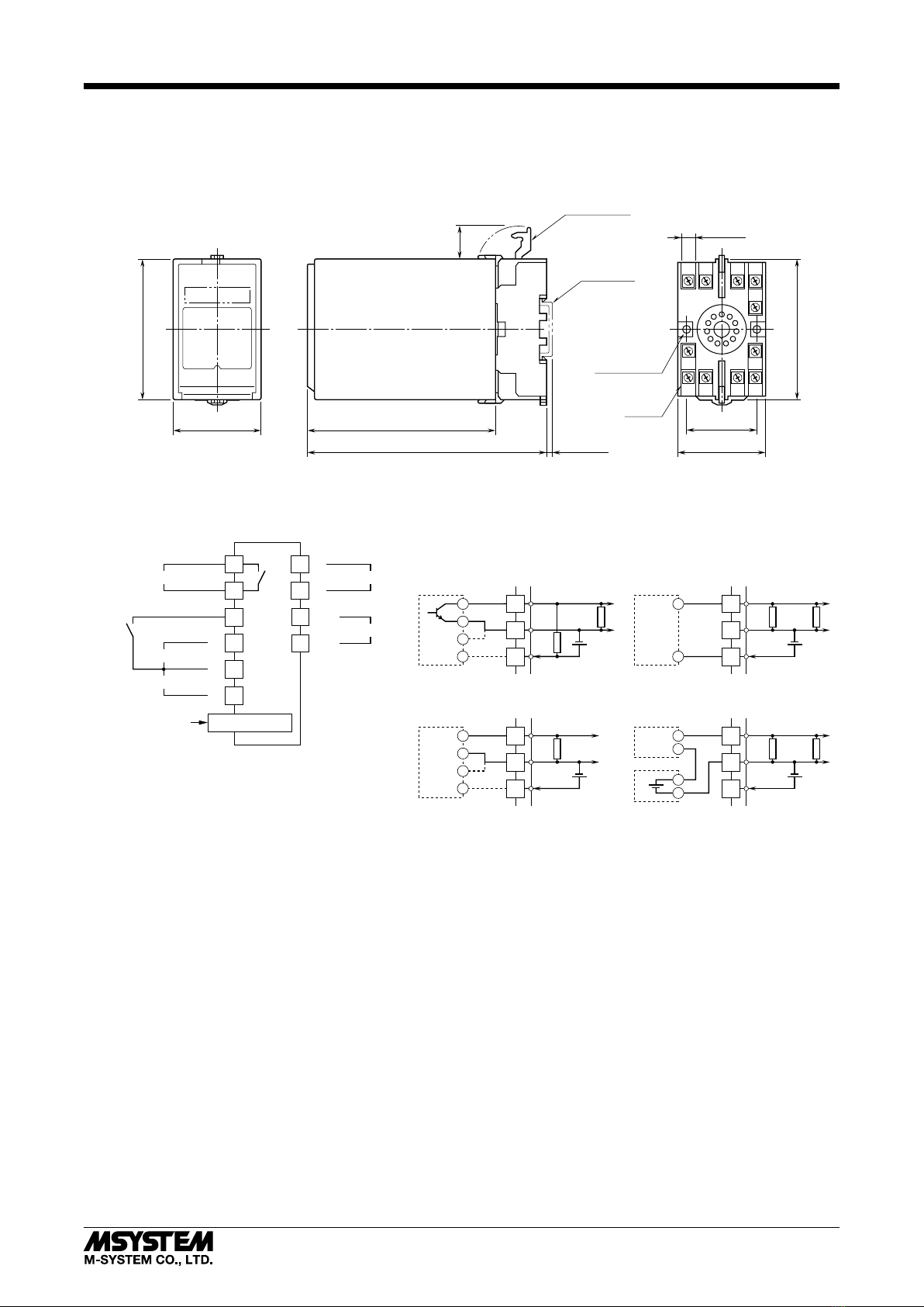
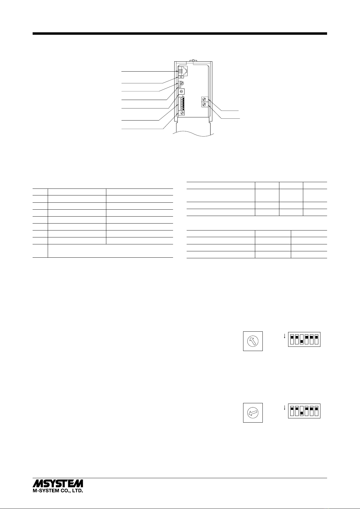
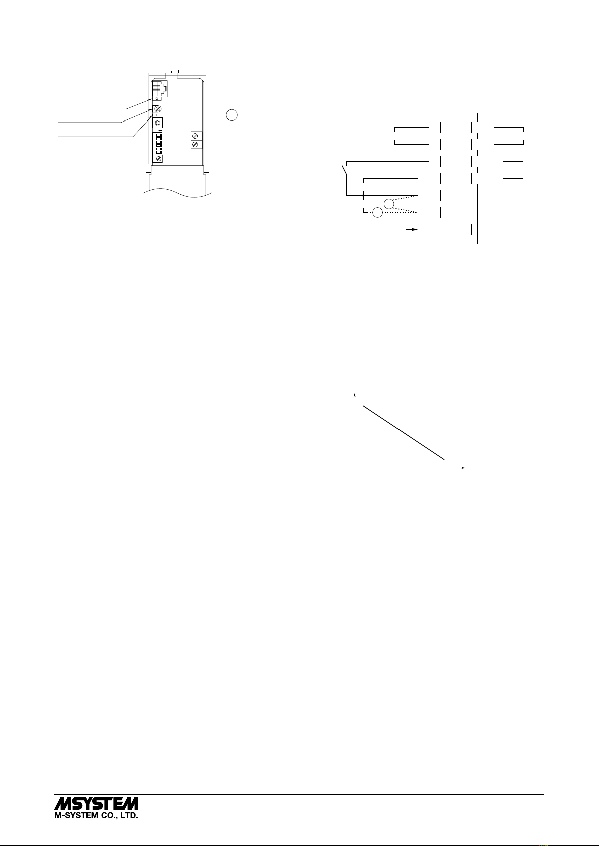
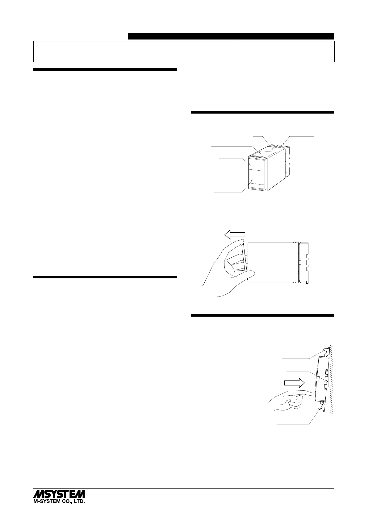
COMPONENT IDENTIFICATION
Body Base Socket
Connection Diagram
Front Cover
Specifications
■HOW TO OPEN THE FRONT COVER:
Hang your finger on the hook at the top of the front cover
and pull.
The shape of base socket may be different
for some models.
INSTALLATION
Detach the yellow clamps located at the top and bottom of
the unit for separate the body from the base socket.
Clamp
(top & bottom)
DIN Rail
35mm wide
Spring Loaded
DIN Rail Adaptor
Shape and size of the base socket
are slightly different with various
socket types.
■DIN RAIL MOUNTING
Set the base socket so that its
DIN rail adaptor is at the bot-
tom. Hang the upper hook at
the rear side of base socket on
the DIN rail and push in the
lower. When removing the
socket, push down the DIN
rail adaptor utilizing a minus
screwdriver and pull.
■WALL MOUNTING
Refer to “EXTERNAL DI-
MENSIONS.”
PULSE ACCUMULATOR
(eld-programmable; built-in excitation) MODEL JPQ2
5-2-55, Minamitsumori, Nishinari-ku, Osaka 557-0063 JAPAN
EM-1579 Rev.3 P. 1 / 8
INSTRUCTION MANUAL

TERMINAL CONNECTIONS
Connect the unit as in the diagram below or refer to the connection diagram on the top of the unit.
■EXTERNAL DIMENSIONS unit: mm (inch)
5678
21
1110
80 (3.15)
50 (1.97) 107 (4.21)
136 (5.35) [3.3 (.13)]
80 (3.15)
20
(.79)
40 (1.57)
50 (1.97)
7.8 (.31)
CLAMP
(top & bottom)
DIN RAIL
35mm wide
2
–
4.5 (.18) dia.
MTG HOLE
25 (.98) deep
11
–
M3.5
SCREW
• When mounting, no extra space is needed between units.
39
4
■CONNECTION DIAGRAM
+
–
OUTPUT
1
2
U(+)
V(–)
POWER
7
8
PU-2x
MODULAR JACK
9
10
ALARM OUTPUT
5
4
6
+
5kΩ
■ Dry Contact
or Mechanical Contact
Input Connection Examples
+
–
–Vsns
PWR
■ 2-Wire Current Pulse
• Built-in Excitation
5
4
6
–
+
Vsns
2-WIRE
PICK-UP
• External DC Supply
5
4
6
–
Vsns
2-WIRE
PICK-UP +
+
DC SUPPLY
–
100Ω
■ Voltage Pulse
5
4
6
+
+
–
–Vsns
PWR
100Ω
–
INPUT
+5
4
6
+
SENSOR EXCITATION
11
RESET
INPUT
JPQ2
5-2-55, Minamitsumori, Nishinari-ku, Osaka 557-0063 JAPAN
Phone: +81(6)6659-8201 Fax: +81(6)6659-8510 E-mail: info@m-system.co.jp
EM-1579 Rev.3 P. 2 / 8

EXPLANATIONS OF TERMS & FUNCTIONS
■COUNT OVERFLOW
Three overflow modes are selectable with the Programming
Unit: Reset, Hold at 100% or Hold at 115%.
In Reset mode, the JPQ2 resets pulse count to zero as soon
as the input reaches the span count value. The span count
is equal to the zero count, thus the JPQ2 never outputs
100% in this sense.
In Hold at 100% mode, the JPQ2 stops counting at 100%
input. The count is held at the span count value, and the
DC output is held at 100%.
In Hold at 115% mode, the JPQ2 continues counting until
115% before holding the count and DC output.
In both modes, the Reset command input resets the count
to zero and the JPQ2 returns to the output equivalent to
zero count.
Input frequency does not affect the pulse counting of this
unit, however, the minimum of 5-microsecond pulse width
(50 msec. for mechanical contact input) is required to ac-
curately count the input pulses.
• Reset Mode
Input
Output
+
Reset Short
Span Count
Min. 500 ms
Open
• Hold at 100% Mode
Input
Output
+
Reset Short
Span Count
Min. 500 ms
Open
• Hold at 115% Mode
Input
Output
+
Reset Short
Span Count
Min. 500 ms
Open
■ALARM OUTPUT
Either Hi or Lo alarm output is supplied by a relay contact.
The alarm setpoint and the deadband (hysteresis) are ad-
justable with the Programming Unit in percentage of the
input range. The alarm setpoint is selectable from -15 to
+115%, while the deadband is from 0 to 20%.
Once the relay contact trips, it is reset to the normal posi-
tion when the counter is reset by the external reset com-
mand.
■RESET INPUT
When a reset input is turned on, the accumulated count
in the internal counter goes back to zero. The JPQ2 com-
pares the input to this internal count for the alarm function,
therefore is affected by reset operations.
The reset input negative is connected to the input common.
Short across the terminals 6 and 11 for the minimum of
500 msec.
■ZERO COUNT, SPAN COUNT
The count value equivalent to 0% output is called ‘Zero
Count,’ while that equivalent to 100% is called ‘Span Count.’
The zero count is usually set to 0, and selectable up to one
count below the span count. The span count is selectable
from one count above the zero count up to 99999999.
When a reset input is turned on, the output goes to 0% ac-
cording to the reset count.
With the ‘Hold at 115%’ overflow mode, the maximum count
range is from 0 to 99999999, and the maximum effective
count is 114999998.
■DETECTING PULSE EDGE
• Open Collector & Mechanical Contact:
OFF (input monitor LED ON) to ON (input monitor LED
OFF) or ON to OFF
• Voltage Pulse
A pulse rise detected when the input voltage goes above
the detecting level (input monitor LED ON); a pulse sink
detected when it goes below the level (input monitor LED
OFF).
• Two-wire Current Pulse
The input resistor (100Ω) converts the current signal (0 –
25mA) into 0 – 2.5V. A pulse rise detected when the volt-
age goes above the detecting level (input monitor LED ON);
a pulse sink detected when it goes below the level (input
monitor LED OFF).
JPQ2
5-2-55, Minamitsumori, Nishinari-ku, Osaka 557-0063 JAPAN
Phone: +81(6)6659-8201 Fax: +81(6)6659-8510 E-mail: info@m-system.co.jp
EM-1579 Rev.3 P. 3 / 8

HARDWARE SETTING & CALIBRATION
■FRONT PANEL CONFIGURATION
5
4
3
2
1
0
9
8
7
6
1
2
3
4
5
6
ON
Span Adj.
Detecting Level Adj.
Detecting Level Adj. Pin
Pulse Amplitude Selector
Input Type Selector
Zero Adj.
Sensor Excitation Adj.
Modular Jack
Input Monitor LED PL1
■PULSE AMPLITUDE (rotary switch) (*) Factory setting
For voltage pulse input, select the pulse amplitude (V p-p)
among the switch positions 0 through 6. For open collector,
mechanical contact or two-wire current pulse input, set the
switch to 7. DO NOT SET to 8 or 9. The power supply to the
unit must be turned off when changing the setting.
SW PULSE AMPLITUDE MAX. INPUT VOLTAGE
0 50 – 100V p-p 50V
1 25 – 50V p-p 50V
2 10 – 25V p-p 25V
3 5 – 10V p-p 10V
4 1 – 5V p-p 5V
5*10.5 – 1V p-p 1V
6*10.1 – 0.5V p-p 0.5V
7(*) Open collector, mechanical contact or two-wire current
pulse
*1. Maximum frequency limited to 50 kHz.
■DIP SWITCH SETTING (*) Factory setting
SW6 is not used. The power supply to the unit must be
turned off when changing the setting.
• Input Type
INPUT TYPE SW1 SW2 SW3
Open collector (*)
Mechanical contact
ON OFF ON
Voltage pulse OFF OFF ON
Two-wire current pulse OFF ON ON
• Noise Filter
NOISE FILTER SW4 SW5
High ON OFF
Low (*) OFF ON
None OFF OFF
‘High’ noise filter is usable for the input frequency 10 Hz or
lower range, and ‘Low’ filter is usable for 500 Hz or lower.
For a mechanical contact input, ‘High’ setting is recom-
mended in order to eliminate unwanted counts caused by
chattering.
■EXAMPLE 1: VOLTAGE PULSE with Amplitude 5V p-p, DC Offset 2.5V, Count Range 0 – 1000
Input type: Voltage Pulse
Input count: Zero count set to 0, Span count set to 1000
ON
123456
Rotary SW DIP SW
5
6
7
8
9
0
1
2
3
4
(Set 0% and 100% range values with the Programming Unit.)
Input amplitude: 1 – 5V p-p
Detecting level: 2.5V (Set to the offset value after it is
scaled by the sensitivity scale.)
Noise filter: None (Choose according to the frequency.)
The rotary switch and DIP switch are configured as shown to the right.
■EXAMPLE 2: VOLTAGE PULSE with Amplitude 24V p-p, DC Offset 12V, Count Range 100 – 10000
Input type: Voltage Pulse
Input count: Zero count set to 100, Span count set to 10000
ON
123456
Rotary SW DIP SW
5
6
7
8
9
0
1
2
3
4
(Set 0% and 100% range values with the Programming Unit.)
Input amplitude: 10 – 25V p-p
Detecting level: 1.2V (Set to the offset value after it is
scaled by the sensitivity scale.)
Noise filter: None (Choose according to the frequency.)
The rotary switch and DIP switch are configured as shown to the right.
JPQ2
5-2-55, Minamitsumori, Nishinari-ku, Osaka 557-0063 JAPAN
Phone: +81(6)6659-8201 Fax: +81(6)6659-8510 E-mail: info@m-system.co.jp
EM-1579 Rev.3 P. 4 / 8

■DETECTING LEVEL (voltage pulse and two-wire current pulse)
Determine the appropriate detecting level referring to the flow chart below.
START
Confirm the Sensitivity Scale in Table 1
below.
Assign the value in the following equation.
Detecting Level (V)*1=
DC Offset (V)*2×Sensitivity Scale
Adjust the detecting level to the value
calculated above following the procedure
explained below.
Confirm open collector or
mechanical contact input.
Adjust the detecting level to
2.0V.
Voltage or two-wire current
pulse input?
No
Yes
*1. Divide a two-wire current pulse input (mA) by 10 and convert it into voltage (V).
*2. Rounded off to one decimal place.
Table 1
SW PULSE AMPLITUDE SENSITIVITY SCALE
0
1
2
3
50 – 100V p-p
25 – 50V p-p
10 – 25V p-p
5 – 10V p-p
1/20
1/10
1/5
1/2
4
5
6
1 – 5V p-p
0.5 – 1V p-p
0.1 – 0.5V p-p
1
5
10
7 Open collector
Mechanical contact
Two-wire current pulse
1
A specific sensitivity scale is applied according to the pulse
amplitude setting. The scaled input voltage is then com-
pared to the preset detecting level.
With DC coupling, the scaled H level voltage must be higher
than the detecting level so that the pulse state is accurately
detected.
• Setting Examples
Voltage Pulse (DC Offset = Pulse Amplitude / 2)
PULSE AMPLITUDE
(Vp-p)
AMPLITUDE
RANGE (Vp-p)
DETECTING
LEVEL (V)
50
50
30
50 – 100
25 – 50
25 – 50
1.3
2.5
1.5
25
15
10
10 – 25
10 – 25
5 – 10
2.5
1.5
2.5
7.5
5
3.5
5 – 10
1 – 5
1 – 5
1.9
2.5
1.8
2
1
0.5
1 – 5
0.5 – 1
0.1 – 0.5
1
2.5
2.5
Two-wire Current Pulse (DC Offset = Pulse Amplitude / 2)
PULSE AMPLITUDE
(mAp-p)
AMPLITUDE
RANGE
DETECTING
LEVEL (V)
15 (1.5Vp-p)
25 (2.5Vp-p)
Set to open collector,
mechanical contact or
two-wire current pulse
0.8
1.3
Set DC offset to 0V for 100Vp-p pulse input.
JPQ2
5-2-55, Minamitsumori, Nishinari-ku, Osaka 557-0063 JAPAN
Phone: +81(6)6659-8201 Fax: +81(6)6659-8510 E-mail: info@m-system.co.jp
EM-1579 Rev.3 P. 5 / 8

• How to Change the Detecting Level
5
4
3
2
1
0
9
8
7
6
1
2
3
4
5
6
ON
Detecting Level Adj.
Detecting Level Adj. Pin
Input Monitor LED PL1
V
–
Connect to Terminal 6
of the base socket.
Voltmeter
A voltmeter of class 0.5 or better accuracy with pointed
probes is required.
1) Connect the negative probe of voltmeter to the terminal 6
of base socket.
2) If you need a noise filter, set the SW4 and SW5 in ad-
vance.
3) Connect the positive probe to the test pin and turn the
Detecting Level Adjustment until the meter shows de-
sired value.
4) Apply input signals and check that input monitor LED
(PL1) blinks according to the input signal.
If the LED does not blink, the detecting level may be out
of pulse amplitude range. Check the pulse amplitude
and the DC offset again and readjust the detecting level.
■SENSOR EXCITATION ADJUSTMENT
You can change the sensor excitation voltage with the sen-
sor excitation adj. located behind the front cover. If you
need to change it, check that the required current is within
the specification.
+
–
OUTPUT
1
2
U(+)
V(–)
POWER
7
8
PU-2x
MODULAR JACK
–
INPUT
+5
4
6
+
EXC.
9
10
ALARM OUTPUT
V
A
Ammeter
Voltmeter
11
RESET
INPUT
• How to Change the Excitation
A voltmeter and ammeter of class 0.5 or better accuracy are
required.
1) Connect the voltmeter across the terminals 4 – 6.
2) Connect the ammeter to terminal 4.
3) Turn the potentiometer until the meter shows the de-
sired value.
Check that the current value indicated on the ammeter
is within the allowable limit. If the value is greater than
the limit, lower the voltage value or connect a separate
power source. Otherwise, the transmitter may fail.
25
5
12
24
60 120
CURRENT (mA)
VOLTAGE (V)
Voltage (V) × Current (A) ≤ 600mW
■ANALOG OUTPUT ADJUSTMENT
This unit is calibrated at the factory to meet the ordered
specifications, therefore you usually do not need any cali-
bration.
For matching the signal to a receiving instrument or in case
of regular calibration, adjust the output as explained in the
following.
• How to Calibrate The Output Signal
Use a signal source and measuring instruments of sufficient
accuracy level. Turn the power supply on and warm up for
more than 10 minutes.
1) ZERO: Apply the number of pulses equivalent to zero
count (or set the input count to zero count using the Pro-
gramming Unit) and adjust output to 0%.
2) SPAN: Apply the number of pulses equivalent to span
count (or set the input count to span count using the Pro-
gramming Unit) and adjust output to 100%.
3) Check ZERO adjustment again with zero count.
4) When ZERO value is changed, repeat the above proce-
dure 1) – 3).
JPQ2
5-2-55, Minamitsumori, Nishinari-ku, Osaka 557-0063 JAPAN
Phone: +81(6)6659-8201 Fax: +81(6)6659-8510 E-mail: info@m-system.co.jp
EM-1579 Rev.3 P. 6 / 8

SOFTWARE SETTING
Please refer to the Operation Manual for Model PU-2x (EM-9255), Section B: (B-1) Introduction, (B-2) General Operation
Description, (B-3) Operation Flowchart for general information.
[GROUP 01]
ITEM MDFY. DATA INPUT DISPLAY DEFAULT CONTENTS
01 S N/A MAINTENANCE SWITCH
0 MTSW : MON.MODE 0: Data indication only.
1 MTSW : PRG.MODE 1: All ‘P’ marked parameters are modifiable.
02 P
Alphabets & No
TG : XXXXXXXXXX N/A Tag name entry (10 characters max.)
03 P Percentage OUTPER XXX.XX N/A Output monitor (%) & simulation output
05 D No input INPPER XXX.XX N/A Input monitor (%)
06 P No input CNT XXXXXXXXX N/A Input count monitor; or setting to a specific count value
07 D No input N/A Input specification selected with the front rotary switch
SW : IN_V 1/20 SW = 0, Voltage pulse input, Sensitivity scale = 1/20
SW : IN_V 1/10 SW = 1, Voltage pulse input, Sensitivity scale = 1/10
SW : IN_V 1/5 SW = 2, Voltage pulse input, Sensitivity scale = 1/5
SW : IN_V 1/2 SW = 3, Voltage pulse input, Sensitivity scale = 1/2
SW : IN_V 1/1 SW = 4, Voltage pulse input, Sensitivity scale = 1/1
SW : IN_V 5/1 SW = 5, Voltage pulse input, Sensitivity scale = 5/1
SW : IN_V 10/1 SW = 6, Voltage pulse input, Sensitivity scale = 10/1
SW : IN_OC, mA SW = 7, Open collector, mechanical contact or two-wire cur-
rent pulse input
SW : no use SW = 8, (not used)
SW : no use SW = 9, (not used)
08 P 0 Input count at power off
0 COUNT UNKEEP Not held (Cold Start)
1 COUNT KEEP Held (Hot Start)
10 P 0 Linearization
0 STRAIGHT Without
1 CURVED With (ITEM 60 to 91 for segment data input)
11 P 0 Count mode
0 UP_EDGE Count at pulse rise
1 DOWN_EDGE Count at pulse sink
2 UPDOWN_EDGE Count at both pulse rise and sink
12 P 0 Count overflow mode
0 115%_HOLD Hold at 115%
1 100%_HOLD Hold at 100%
2 100%_RESET Reset at 100%
14 P Numeric LO XXXXXXXXX 0 Input zero count (0% input) (0 to 99999999)
15 P Numeric HI XXXXXXXXX 1000 Input span count (100% input) (0 to 99999999)
19 P Percentage FINZER XXX.XX 0.00 Fine zero adjustment
OUTPER XXX.XX When data is entered, output (%) is shown.
20 P Percentage FINSPN XXX.XX 100.00 Fine span adjustment
OUTPER XXX.XX When data is entered, output (%) is shown.
21 P 1 Alarm mode
0NO ALARM No alarm trip
1UPPER ALARM High alarm trip
22 P Percentage ALARM XXX.XX 100.00 Alarm setpoint (-15.00 to +115.00%)
24 P Seconds ALTIME XXXX.X 3.0 Alarm delay at the startup (2.0 to 1000.0 seconds)
60
61
:
:
:
90
91
P
P
:
:
:
P
P
Percentage
Percentage
:
:
:
Percentage
Percentage
X (01) : XXX.XX
Y (01) : XXX.XX
:
:
:
X (16) : XXX.XX
Y (16) : XXX.XX
0.00
0.00
0.00
0.00
Linearization table (16 points)
Set at the maximum of 16 pairs of input (X) and output (Y)
calibration points in %. Fill data from the lowest ITEM
No. from the lowest calibration point and add as many as
required. The output in the undefined range is maintained
at the value of the first and the last calibration points.
Modication Code
D: No modification (writing) possible. Used only for monitoring (reading).
S: Modifiable at any time.
P: Modifiable only when the MAINTENANCE SWITCH is in the “PRG” mode.
ROM Version Indication
[GROUP 00] [ITEM 99]
JPQ2
5-2-55, Minamitsumori, Nishinari-ku, Osaka 557-0063 JAPAN
Phone: +81(6)6659-8201 Fax: +81(6)6659-8510 E-mail: info@m-system.co.jp
EM-1579 Rev.3 P. 7 / 8

■COUNT MODE
ITEM 11 specifies at which point of the pulse waveforms the count should be added.
• Count at pulse rise
H (OFF)
L (ON)
• Count at both edges
H (OFF)
L (ON)
• Count at pulse sink
H (OFF)
L (ON)
■LINEARIZATION TABLE
The I/O curve is approximated at 16-point segments. Set
only the required pairs of I/O points. Refer to the figure
below.
X (nn) : Input %
Y (nn) : Output %
Range : -15.00 to +115.00%
-15%
0
Y01
X02 X03 X04 X05 +115%
Y02
X01
Y03
Y04
+100% Y05
INPUT
OUTPUT
-5%
[GROUP 01]
ITEM MDFY. DATA EXAMPLE
60
61
P
P
X (01) : XXX.XX
Y (01) : XXX.XX
62
63
P
P
X (02) : XXX.XX
Y (02) : XXX.XX
64
65
P
P
X (03) : XXX.XX
Y (03) : XXX.XX
66
67
P
P
X (04) : XXX.XX
Y (04) : XXX.XX
68
69
P
P
X (05) : XXX.XX
Y (05) : XXX.XX
70
71
P
P
X (06) : XXX.XX
Y (06) : XXX.XX
72
73
P
P
X (07) : XXX.XX
Y (07) : XXX.XX
74
75
P
P
X (08) : XXX.XX
Y (08) : XXX.XX
76
77
P
P
X (09) : XXX.XX
Y (09) : XXX.XX
78
79
P
P
X (10) : XXX.XX
Y (10) : XXX.XX
80
81
P
P
X (11) : XXX.XX
Y (11) : XXX.XX
82
83
P
P
X (12) : XXX.XX
Y (12) : XXX.XX
84
85
P
P
X (13) : XXX.XX
Y (13) : XXX.XX
86
87
P
P
X (14) : XXX.XX
Y (14) : XXX.XX
88
89
P
P
X (15) : XXX.XX
Y (15) : XXX.XX
90
91
P
P
X (16) : XXX.XX
Y (16) : XXX.XX
Modication Code
S: Modifiable at any time.
P: Modifiable only when the MAINTENANCE SWITCH is in
the “PRG” mode.
CHECKING
1) Terminal wiring: Check that all cables are correctly con-
nected according to the connection diagram.
2) Power input voltage: Check voltage across the terminal
7 – 8 with a multimeter.
3) Input: Check that the input signal is within 0 – 100% of
the full-scale.
4) Output: Check that the load resistance meets the de-
scribed specifications.
MAINTENANCE
Regular calibration procedure is explained below:
■CALIBRATION
Warm up the unit for at least 10 minutes. Apply 0%, 25%,
50%, 75% and 100% input signal. Check that the output
signal for the respective input signal remains within accu-
racy described in the data sheet. When the output is out of
tolerance, recalibrate the unit according to the “ANALOG
OUTPUT ADJUSTMENT” procedure.
LIGHTNING SURGE PROTECTION
M-System offers a series of lightning surge protector for
protection against induced lightning surges. Please contact
M-System to choose appropriate models.
JPQ2
5-2-55, Minamitsumori, Nishinari-ku, Osaka 557-0063 JAPAN
Phone: +81(6)6659-8201 Fax: +81(6)6659-8510 E-mail: info@m-system.co.jp
EM-1579 Rev.3 P. 8 / 8
Table of contents