M-TI FREEDOM MICRO II User manual

1
P/N M0494 rev A ©2022 MTI All Rights Reservedwww.MTIGS.com | T:800.897.1350
Instructions & Videos:
AR: attar.store.mobiletechinc.com
COR: att.store.mobiletechinc.com
Product Ordering:
AR: attar.store.mobiletechinc.com
COR: att.store.mobiletechinc.com
Questions & Troubleshooting:
800.897.1350
Order Inquiries:
Product Manual for
Freedom Micro®II Mechanical
High Security
DO NOT REMOVE FROM STORE
Contents
1. Fixture/Track Reference Guide 2
2. OEM Power Cable Routing 3
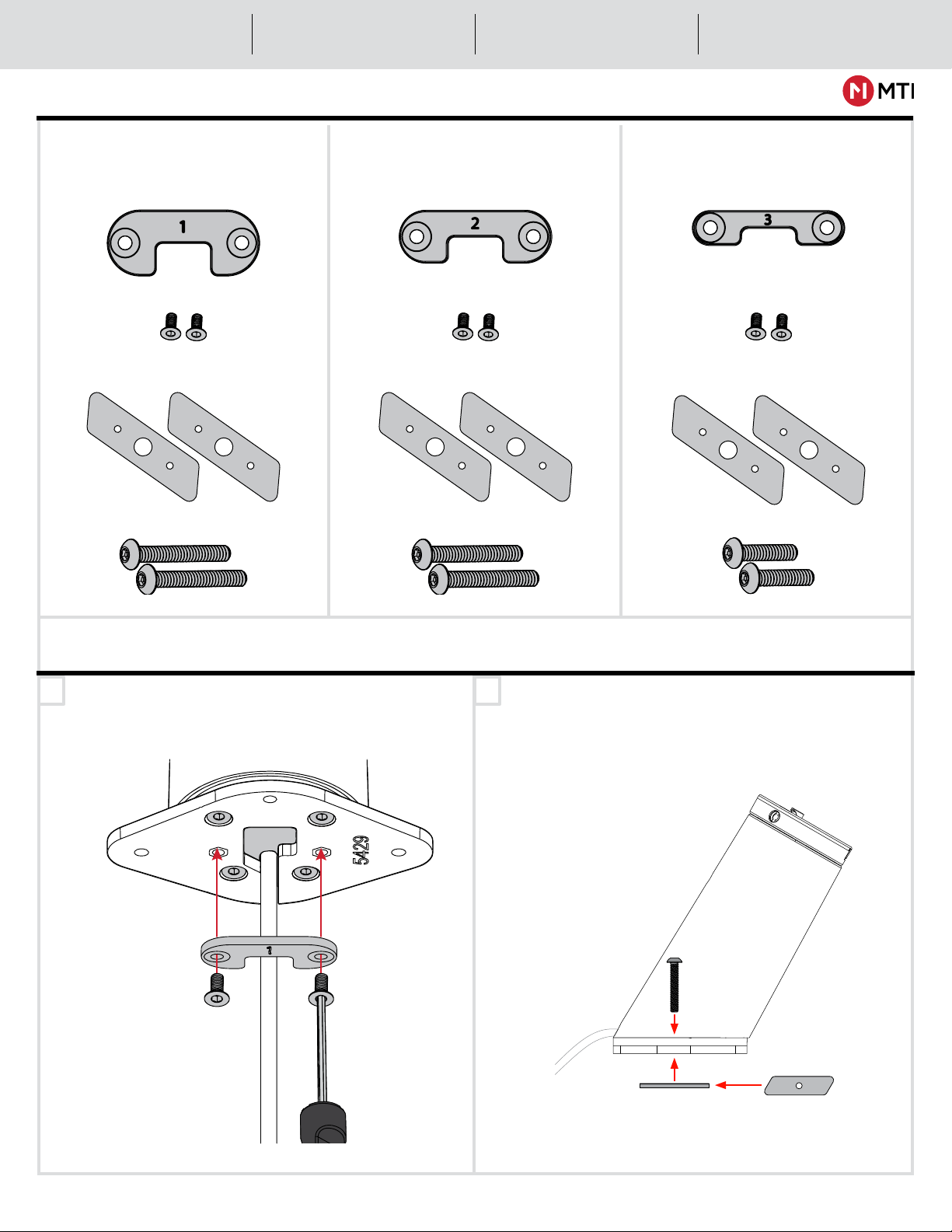
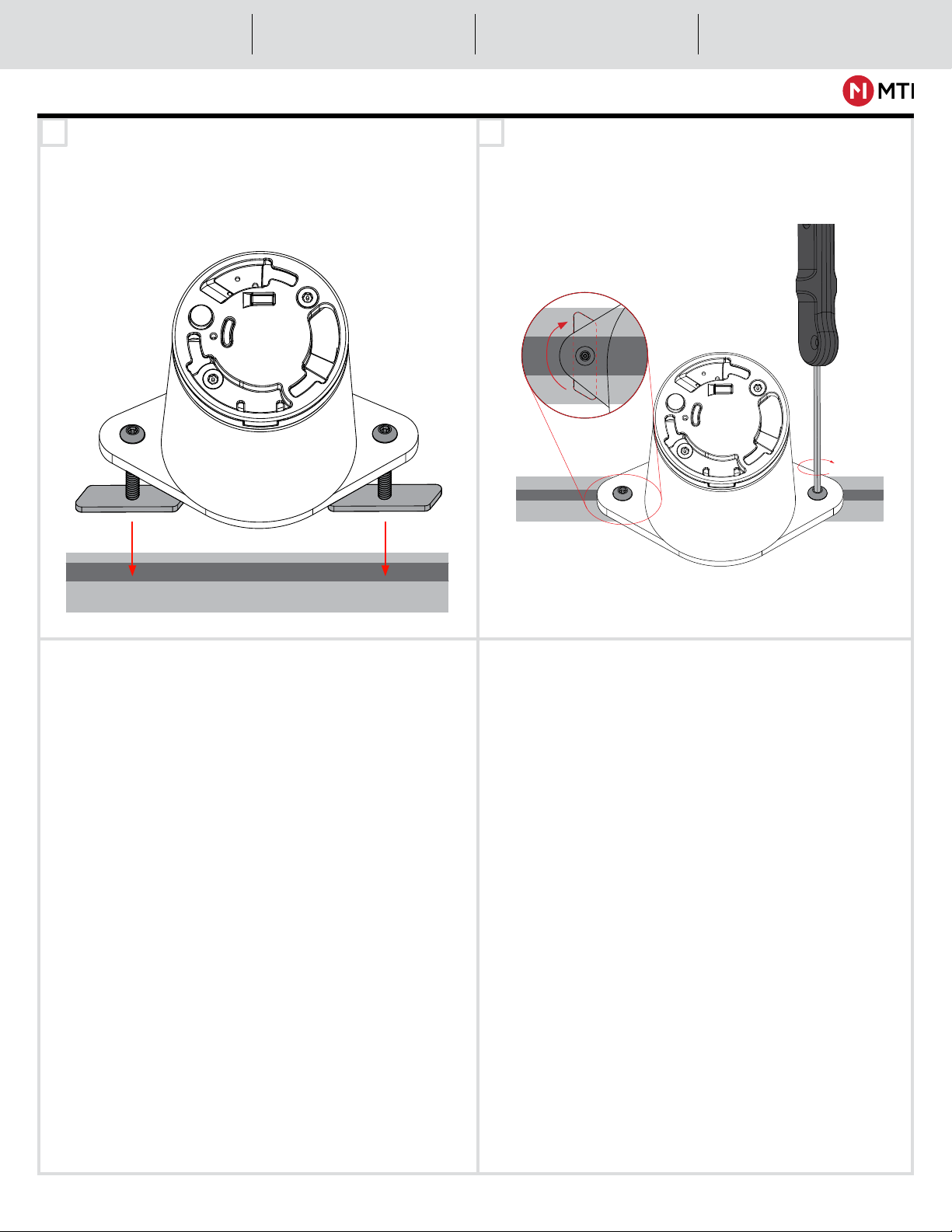
3. Track Fixture Mounting 4
4. Entertainment Fixture (Through hole) 6
5. Speedbracket™ Merchandising 7
6. Speedbracket™ Removal 9
7. Removing OEM power Cable 10
8. Dimensions 10
For additional support, please reach out to our
Contact Center at 800-897-1350
WARNING: MTI products contains chemicals known to the State of California to cause cancer and birth defects or other reproductive harm.
Proposition 65, California Health & Safety Code Section 25249.6 et seq. Visit oehha.ca.gov for more information.
-CONTROLLED DOCUMENT- M0494 A-0 Status: Approved ECO-113512
ECO-113512

2
P/N M0494 rev A ©2022 MTI All Rights Reservedwww.MTIGS.com | T:800.897.1350
Instructions & Videos:
AR: attar.store.mobiletechinc.com
COR: att.store.mobiletechinc.com
Product Ordering:
AR: attar.store.mobiletechinc.com
COR: att.store.mobiletechinc.com
Questions & Troubleshooting:
800.897.1350
Order Inquiries:
Entertainment Fixture (Through Hole)
FIXTURE/TRACK REFERENCE GUIDE FOR SECURITY INSTALLATION
Through Track with Solid Surface Panel Wall Track
Aluminum TrackThrough Track with Acrylic Top
Through Track with Grommet
-CONTROLLED DOCUMENT- M0494 A-0 Status: Approved ECO-113512
ECO-113512

Instructions & Videos:
AR: attar.store.mobiletechinc.com
COR: att.store.mobiletechinc.com
Product Ordering:
AR: attar.store.mobiletechinc.com
COR: att.store.mobiletechinc.com
Questions & Troubleshooting:
800.897.1350
Order Inquiries:
3
P/N M0494 rev A ©2022 MTI All Rights Reservedwww.MTIGS.com | T:800.897.1350
1
OEM POWER CABLE ROUTING
3
Riser, spacers, and baseplate come pre-assembled as shown. Upon opening the box, loosen all four screws 3-4 turns to
route OEM power cable in next step. If your base has track adapter baseplate, follow these same steps.
Feed OEM power cable included with device through
cable channel between the riser and baseplate. Cable
should be routed such that the device end of the cable
is inserted to the back of the riser and exits from the
front of the riser.
2Tighten all four baseplate screws after routing OEM
power cable.
REQUIRED TOOLS
-CONTROLLED DOCUMENT- M0494 A-0 Status: Approved ECO-113512
ECO-113512

4
P/N M0494 rev A ©2022 MTI All Rights Reservedwww.MTIGS.com | T:800.897.1350
Instructions & Videos:
AR: attar.store.mobiletechinc.com
COR: att.store.mobiletechinc.com
Product Ordering:
AR: attar.store.mobiletechinc.com
COR: att.store.mobiletechinc.com
Questions & Troubleshooting:
800.897.1350
Order Inquiries:
TRACK KIT CONFIGURATIONS
1 2Attach Spacer Adapter with the spacer screws using the
Double-Sided System Tool. Make sure that the spacer
number is facing down.
Spacer Adapter Spacer Adapter Spacer Adapter
Spacer ScrewsSpacer ScrewsSpacer Screws
Track Mounting Tabs Track Mounting Tabs Track Mounting Tabs
Mounting Tab Screws Long Mounting Tab Screws Long Mounting Tab Screws Short
Solid Surface, Grommet
or Radial Track
Through Track
with Acrylic Top
Aluminum Track
or Panel Wall
TRACK INSTALLATION
Rotate the mounting tabs onto the mounting screws
until flush with bottom of screw. Make sure the
DOTTED side of the mounting tabs is facing DOWN.
-CONTROLLED DOCUMENT- M0494 A-0 Status: Approved ECO-113512
ECO-113512

5
P/N M0494 rev A ©2022 MTI All Rights Reservedwww.MTIGS.com | T:800.897.1350
Instructions & Videos:
AR: attar.store.mobiletechinc.com
COR: att.store.mobiletechinc.com
Product Ordering:
AR: attar.store.mobiletechinc.com
COR: att.store.mobiletechinc.com
Questions & Troubleshooting:
800.897.1350
Order Inquiries:
3 4
TRACK INSTALLATION
Align the mounting tabs and press them into the track. Hold the position steady with one hand. With your
other hand use the Double-Sided System Tool to turn
the screws to move the mounting tabs into position.
Tighten screws to lock position to the fixture.
-CONTROLLED DOCUMENT- M0494 A-0 Status: Approved ECO-113512
ECO-113512

Instructions & Videos:
AR: attar.store.mobiletechinc.com
COR: att.store.mobiletechinc.com
Product Ordering:
AR: attar.store.mobiletechinc.com
COR: att.store.mobiletechinc.com
Questions & Troubleshooting:
800.897.1350
Order Inquiries:
6
P/N M0494 rev A ©2022 MTI All Rights Reservedwww.MTIGS.com | T:800.897.1350
1 2
3
Align bottom plate to slot adapter.
Insert the Freedom Micro®II MHS position into the
hole.
Secure the Freedom Micro®II Mechanical MHS position
with the knob.
ENTERTAINMENT FIXTURE (THROUGH HOLE) INSTALLATION
-CONTROLLED DOCUMENT- M0494 A-0 Status: Approved ECO-113512
ECO-113512

7
P/N M0494 rev A ©2022 MTI All Rights Reservedwww.MTIGS.com | T:800.897.1350
Instructions & Videos:
AR: attar.store.mobiletechinc.com
COR: att.store.mobiletechinc.com
Product Ordering:
AR: attar.store.mobiletechinc.com
COR: att.store.mobiletechinc.com
Questions & Troubleshooting:
800.897.1350
Order Inquiries:
1
3
2
4
SPEEDBRACKET™ MERCHANDISING
Loosen the center screw on the SpeedBracket™to
loosen the bracket arms.
Place the phone into the SpeedBracket™.
Extend the SpeedBracket™arms as far as needed.
The bracket arms move simultaneously in pairs (top &
bottom, and left & right).
Adjust the SpeedBracket™to fit the device snugly.
Open the top and bottom bracket arms,
then the side arms, in that order.
1.
2.
2.
1.
-CONTROLLED DOCUMENT- M0494 A-0 Status: Approved ECO-113512
ECO-113512

Instructions & Videos:
AR: attar.store.mobiletechinc.com
COR: att.store.mobiletechinc.com
Product Ordering:
AR: attar.store.mobiletechinc.com
COR: att.store.mobiletechinc.com
Questions & Troubleshooting:
800.897.1350
Order Inquiries:
8
P/N M0494 rev A ©2022 MTI All Rights Reservedwww.MTIGS.com | T:800.897.1350
7 8
65
SPEEDBRACKET™ MERCHANDISING
Tighten the center screw on the SpeedBracket™ to
secure the bracket arms in place around the device.
After tightening screw, wiggle the arms to ensure they
have fully engaged the lock teeth, then re-check screw
for tightness.
Place device back onto puck.
Rotate the device and SpeedBracket™clockwise on the
puck until it locks into place.
*click*
Once OEM cable has been routed (page 3) plug into
device.
-CONTROLLED DOCUMENT- M0494 A-0 Status: Approved ECO-113512
ECO-113512

Instructions & Videos:
AR: attar.store.mobiletechinc.com
COR: att.store.mobiletechinc.com
Product Ordering:
AR: attar.store.mobiletechinc.com
COR: att.store.mobiletechinc.com
Questions & Troubleshooting:
800.897.1350
Order Inquiries:
9
P/N M0494 rev A ©2022 MTI All Rights Reservedwww.MTIGS.com | T:800.897.1350
1
3
2
4Remove the SpeedBracket™ from the Freedom Micro®
II Puck, then release and remove the Freedom Micro®II
tool.
With the Freedom Micro®II tool held in the twisted
position, rotate the SpeedBracket™ counterclockwise.
Twist the Freedom Micro®II tool clockwise 45 degrees
and hold it in place.
Insert the crescent end of the Freedom Micro®II tool
into the opening to the right of the LED.
REMOVING SPEEDBRACKET™ FROM PUCK
-CONTROLLED DOCUMENT- M0494 A-0 Status: Approved ECO-113512
ECO-113512

Instructions & Videos:
AR: attar.store.mobiletechinc.com
COR: att.store.mobiletechinc.com
Product Ordering:
AR: attar.store.mobiletechinc.com
COR: att.store.mobiletechinc.com
Questions & Troubleshooting:
800.897.1350
Order Inquiries:
10
P/N M0494 rev A ©2022 MTI All Rights Reservedwww.MTIGS.com | T:800.897.1350
1 2
REMOVING OEM CABLE FROM DEVICE
Remove OEM cable from device. Detatch Riser from fixture and route OEM cable
through (reverse order page 3. step 2)
1.11”
MAXIMUM: 180mm H x 90mm W
MINIMUM: 118mm H x 65mm W
SPEEDBRACKET™ DIMENSIONS
-CONTROLLED DOCUMENT- M0494 A-0 Status: Approved ECO-113512
ECO-113512
Other manuals for FREEDOM MICRO II
3
Other M-TI Car Alarm manuals