M-TI Proforma 300i User manual

MTI Instruments Technical Manual 7001-0005
Revision 1.0 November 5, 2013
Proforma™ 300i Series
Measurement for Semi Conducting, Semi Insulating, and Photo Voltaic Wafers
Users Manual
MTI Instruments Incorporated
325 Washington Avenue Extension, Albany, New York 12205 USA
█ Phone (518) 218-2550 or 800-342-2203 (USA Only) █ Fax (518) 218-2506
█ Web www.mtiinstruments.com █ Email sales@mtiinstruments.com

This page was intentionally left blank

MTI Instruments Technical Manual 7001-0005
Revision 1.0 November 5, 2013
i
Revision History
Rev 1.0.............. Initial Release.

MTI Instruments Technical Manual 7001-0005
Revision 1.0 November 5, 2013
ii
WARRANTY
Seller warrants to the Purchaser that equipment to be delivered hereunder which is of Seller's own
manufacture will be free from defects in material or workmanship and will be of the kind and quality
designed or specified in the contract. Any parts of the equipment which have been purchased by Seller
are warranted only to the extent of the original manufacturer's warranty.
This warranty shall apply only to defects appearing within 1 year from the date of shipment by Seller. If
the equipment delivered hereunder does not meet the above warranty, and if the Purchaser promptly
notifies Seller, Seller shall thereupon correct any defect, including nonconformance with the
specifications, either, at its option, by repairing any defective or damaged parts of the equipment, or by
making available at Seller's plant necessary repaired or replacement parts. No allowance will be made for
repairs or alterations made by others without Seller's written consent or approval. Seller assumes no
responsibility for damage caused by improper installation or by operation in violation of its rated operating
condition, intentional or otherwise, or by improper handling or maintenance. The liability of Seller under
this warranty (except as to title), or for any loss or damage to the equipment, whether the claim is based
on contract or negligence, shall not in any case exceed the cost of correcting defects in the equipment as
herein provided and upon the expiration of the warranty period of all such a liability shall terminate. The
foregoing shall constitute the exclusive remedy of the purchaser and the exclusive liability of the Seller.
The foregoing warranty is exclusive and in lieu of all warranties, whether written, oral, implied or statutory
(except as to title). There are no warranties which extend beyond those expressly stated in this contract.
FCC NOTICES
This equipment generates, uses, and can radiate radio frequency energy and, if not installed and used in
accordance with the manufacturer’s instruction manual, may cause interference with radio and television
reception. This equipment has been designed as a Class A digital device of the FCC rules. These limits
are designed to provide reasonable protection against harmful interference in a commercial installation.
However, there is no guarantee that interference will not occur in a particular installation. If this equipment
does cause harmful interference, which can be determined by turning the equipment off and on, you are
encouraged to try to correct the interference by one or more of the following measures:
•Relocate the instrument with respect to the other device.
•Plug the instrument into a different outlet so that the instrument and the other device are on different
branch circuits.
If necessary, consult a representative of MTI Instruments. You may find the following booklet helpful: FCC
Interference Handbook, 1986, available from the U.S. Government Printing Office, Washington, D.C.
20402, Stock No. 004-000-00450-7.
Information in this manual is subject to change without notice.
© 2013 MTI Instruments

MTI Instruments Technical Manual 7001-0005
Revision 1.0 November 5, 2013
iii
SAFETY WARNINGS
Warning Symbol Definitions
DISCLAIMERS
Language Requirements
Use Requirements
Electrical Shock Hazard Areas
T3.15A, 250V
100-240V, 50/60Hz, 50W
PROFORMA 300i SERIES
NON CONTACT THICKNESS MEASUREMENT SYSTEM
MTI Instruments Inc.
325 Washington Ave Ext
Albany NY 12065, USA
Shipping Shipping Shipping
SHOCK HAZARD: AC MAINS AREA
SHOCK HAZARD: DO NOT INSERT FOREIGN OBJECTS
Electrical Shock/Electrocution Hazard.
DISCLAIMER: EU LANGUAGE REQUIREMENTS
This is the Original Instructions version of the User Manual. It is illegal to
operate this equipment in a European Union (EU) Member State unless the
manual is written in an official language of the Member State. Contact MTI
Instruments for the availability of translated manuals.
WARNING: ELECTRICAL SHOCK/ELECTROCUTION HAZARD
This equipment is connected to AC mains power. There are no user
serviceable parts within the controller box. Do not attempt to open the
controller box or insert foreign objects into the box vent openings.
DISCLAIMER: USE OTHER THAN INTENDED PURPOSE
Using this product in a manner or a purpose other than the manner or purpose
specified by the manufacturer may impair the safety features of this product.

MTI Instruments Technical Manual 7001-0005
Revision 1.0 November 5, 2013
iv
TABLE OF CONTENTS
WARRANTY.................................................................................................................................................. ii
FCC NOTICES.............................................................................................................................................. ii
SAFETY WARNINGS ...................................................................................................................................iii
Warning Symbol Definitions ......................................................................................................................iii
DISCLAIMERS..............................................................................................................................................iii
TABLE OF CONTENTS............................................................................................................................... iv
LIST OF FIGURES........................................................................................................................................v
1 INTRODUCTION ...................................................................................................................................1
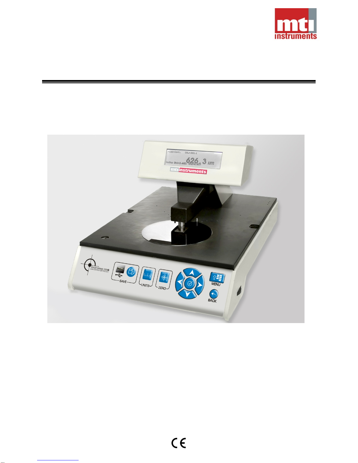
1.1 Proforma™ 300i Series System Description..................................................................................1
1.2 Proforma™ 300i Series Specifications...........................................................................................1
1.3 Receiving Inspection Procedure.....................................................................................................1
2 INSTALLATION INSTRUCTIONS.........................................................................................................3
2.1 Handling..........................................................................................................................................3
2.2 Environmental Considerations........................................................................................................3
2.3 System Setup .................................................................................................................................4
2.3.1 Proforma™ 300i and Proforma™ 300Gi Setup.......................................................................4
2.3.4 Proforma™ 300OEMi Controller Setup...................................................................................6
2.3.5 Proforma™ 300OEMi Initial Probe Setup ...............................................................................7
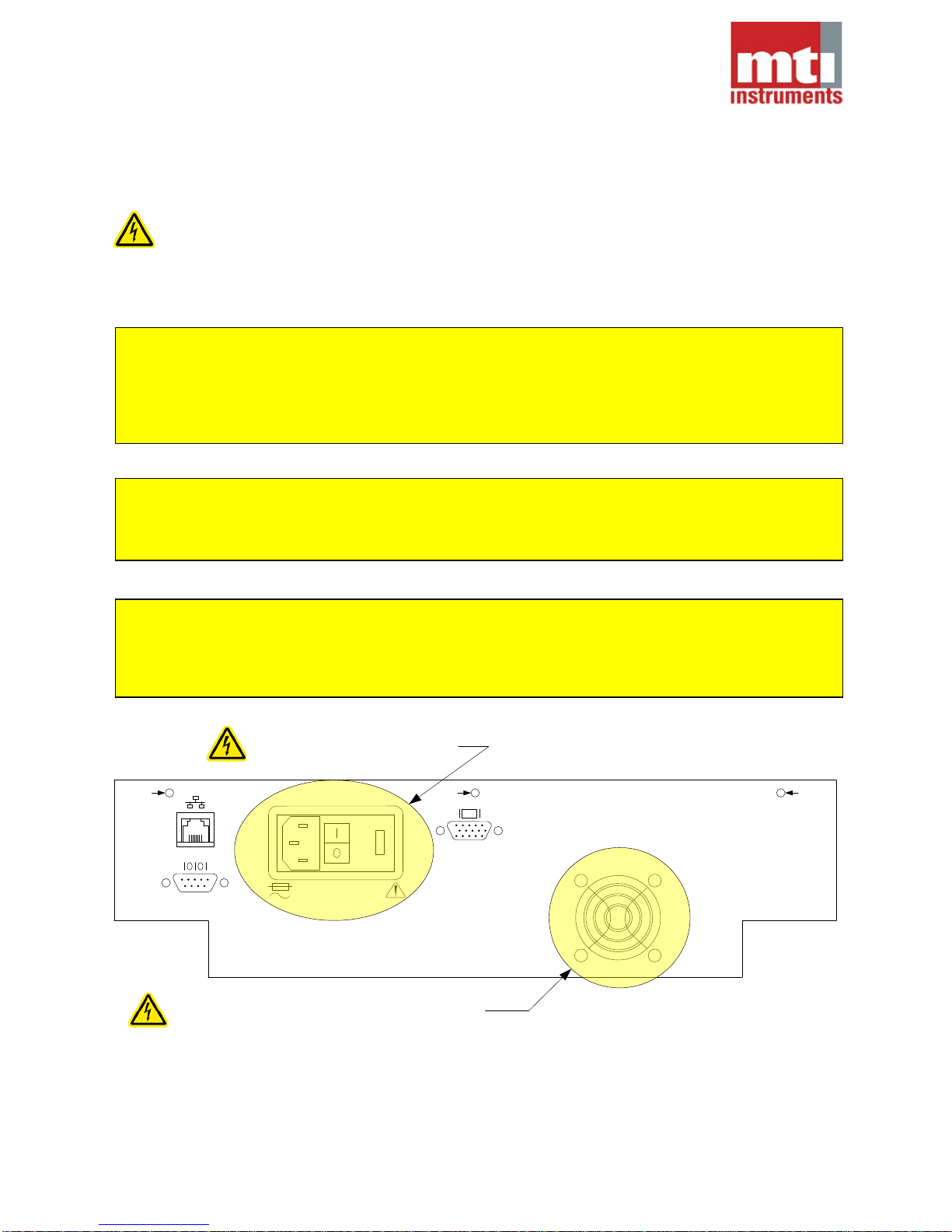
2.3.6 Electrical Connections.............................................................................................................8
2.3.7 Power Up.................................................................................................................................8
3 OPERATIONAL INSTRUCTIONS .........................................................................................................9
3.1 Proforma™ 300i and Proforma™ 300Gi ........................................................................................9
3.1.1 Menu Structure Proforma™ 300i...........................................................................................10
3.1.2 Menu Structure Proforma™ 300Gi........................................................................................11
3.1.3 Keypad Functions..................................................................................................................12
3.1.3.2 Units...................................................................................................................................12
3.1.3.3 Zero....................................................................................................................................12
3.1.3.4 Menu..................................................................................................................................12
3.1.3.5 Back () ............................................................................................................................12
3.1.3.6 Left (), Right (), Up (), Down () Arrows..................................................................12
3.1.3.7 Select ()...........................................................................................................................12
3.1.4 Menu Items............................................................................................................................12
3.1.4.1 Mode..................................................................................................................................12
3.1.4.1.1 Continuous.........................................................................................................................12
3.1.4.1.2 5 Point................................................................................................................................12
3.1.4.1.3 Bow....................................................................................................................................12
3.1.4.2 Calibrate.............................................................................................................................13
3.1.4.3 Limits..................................................................................................................................13
3.1.4.4 Rounding............................................................................................................................13
3.1.4.5 Setup..................................................................................................................................13
3.1.4.5.2 Ethernet .............................................................................................................................13
3.1.4.5.3 Export.................................................................................................................................13
3.1.4.5.4 Export to.............................................................................................................................13
3.1.4.5.5 Lamps (Profoma™ 300Gi only).........................................................................................13
3.1.4.5.6 Raw Volts...........................................................................................................................14
3.1.4.5.7 Resolution..........................................................................................................................14
3.1.4.5.8 RS-232...............................................................................................................................14
3.1.4.5.9 Factory...............................................................................................................................14
3.1.4.5.10 Update............................................................................................................................14
3.1.4.5.11 Version...........................................................................................................................14
3.1.5 Calibration Procedure............................................................................................................15
3.1.6 Operational Modes................................................................................................................16
3.1.6.1 Continuous.........................................................................................................................16

MTI Instruments Technical Manual 7001-0005
Revision 1.0 November 5, 2013
v
3.1.6.2 5-Point Mode......................................................................................................................17
3.1.6.3 Bow Mode..........................................................................................................................18
3.1.7 Functions...............................................................................................................................19
3.1.7.1 Zero....................................................................................................................................19
3.1.7.2 Keyboard Lock...................................................................................................................19
3.1.8 Adjusting the Top Probe........................................................................................................20
3.2 Proforma™ 300OEMi ...................................................................................................................21
3.2.1 Setting the final probe gap on the Proforma™ 300OEMi......................................................21
4 MAINTENANCE...................................................................................................................................22
4.1 Cleaning........................................................................................................................................22
4.1.1 Product Surfaces...................................................................................................................22
4.1.2 Probes ...................................................................................................................................22
Do not use water to clean the probe surfaces. If the probe surfaces become contaminated,
isopropyl alcohol with a lint free cloth may be used. ...........................................................................22
4.1.3 Display...................................................................................................................................22
4.2 Probe/Amplifier Calibration...........................................................................................................22
LIST OF FIGURES
Figure 1:Rear Panel......................................................................................................................................4
Figure 2:Table Features................................................................................................................................5
Figure 3: Drill Diagram for Proforma™ 300OEMi .........................................................................................6
Figure 4:OEM Probe Dimensions .................................................................................................................7
Figure 5:Proforma™ 300i and 300Gi Front Panel Keyboard........................................................................9
Figure 6:Proforma™ 300i and 300Gi Display...............................................................................................9
Figure 7:Proforma™ 300i Menu Structure..................................................................................................10
Figure 8:Proforma™ 300Gi Menu Structure ...............................................................................................11
Figure 9:Profoma™ 300i and 300Gi Display in Menu Mode ......................................................................12
Figure 10:Adjusting the Top Probe .............................................................................................................20
Figure 11:Proforma™ 300i Data Logger Program......................................................................................21

MTI Instruments Technical Manual 7001-0005
Revision 1.0 November 5, 2013
1
1 INTRODUCTION
1.1 Proforma™ 300i Series System Description
Proforma 300i utilizes MTI’s Push-Pull Capacitance technology to accurately and reliably measure Semi
Conducting, Semi Insulating, and Photovoltaic Wafers up to 300mm.
1.2 Proforma™ 300i Series Specifications
300i 300Gi 300OEMi1
Accuracy2: ±0.25um ±0.25um ±0.25um
Repeatability3: ±0.25um ±0.25um ±0.25um
Resolution: 0.05um 0.05um 0.05um
Response Time: 60ms 60ms Custom
Supported Wafer Sizes: 50-300mm 50-300mm Custom
Wafer Thickness Range: 100-1000um 100-1000um Custom
Known Supported Materials4: Si, Ge, InP Si, Ge, GaAs, InP Si, Ge, InP
Weight: 12.3kg 12.4kg 5.9kg
Dimensions (LxWxH): 482x330x279mm 482x330x279mm 483x388x89mm
Temperature (Operational): 15-40ºC 15-40ºC 15-40ºC
Electrical Input (Voltage): 100-240VAC 100-240VAC 100-240VAC
Electrical Input (Frequency): 50-60Hz 50-60Hz 50-60Hz
Electrical Input (Power): 50Watts 50Watts 50Watts
Data Interfaces: LCD, RS232, LCD, RS232, RS232, Ethernet
Ethernet, USB Ethernet, USB
1.3 Receiving Inspection Procedure
The Proforma™ 300i series products are shipped from MTII fully assembled and packed in a cardboard
carton with foam supports to guard against shipping damage. If a heavy duty shipping case was ordered,
the product will be in the heavy duty shipping case and the heavy duty shipping case will be packed in a
cardboard carton. Upon receipt, perform the following procedure before using the unit to perform
dimensional measurements:
1) Inspect the exterior of the shipping carton. Note any obvious damage. If shipping damage is
evident, file a claim with the carrier.
2) Remove the product from the carton and inspect for damage. Do not lift the instrument by
grasping the LCD display or upper probe arm assembly.
3) If any problems were found contact MTII at 1-518-218-2550.
1The OEM model consists of the acquisition system and probes only. As such, several parameters will
be dependant on the custom installation parameters. Contact MTI Instruments to discuss custom
applications and expected performance in these applications.
2At constant 22ºC.
3Within limits of repositioning.
4The ability to measure can vary dependant on several factors (such as bulk resistivity).
CAUTION
The Proforma™ Series products are sensitive to Electrostatic Discharge (ESD). Use proper ESD
techniques when handling this product.
CAUTION
Do not move the Proforma™ 300i or Proforma™ 300Gi by grasping the display housing or the upper
probe arm.

MTI Instruments Technical Manual 7001-0005
Revision 1.0 November 5, 2013
2
Return Shipment Procedure
Contact MTI Instruments, Inc. at 1-518-218-2550 to receive return authorization prior to shipping the
instrument. Reference the instrument's name, model and serial numbers on all correspondence. Be sure
to include a brief description of the reason for the return. Place the instrument in the original shipping
carton (if available) and forward prepaid to:
MTI Instruments, Inc.
Supervisor of Manufacturing
325 Washington Avenue Extension
Albany, NY 12205-5505
Mark "RMA" and the RMA number (if a number is issued) on the outside of the box. If the original packing
materials are not available:
1) Replace the 3 rear panel shipping screws. The suggested location that these should have been
stored in is the attached plastic bag that is used for the alignment pins. If they have been lost, the
correct type screw is 4-40x1/4” flat head.
2) Wrap the instrument in plastic or heavy paper.
3) Place packing material around all sides of the instrument and pack it in a cardboard carton.
4) Place instrument on a suitable carrier, such as a pallet.

MTI Instruments Technical Manual 7001-0005
Revision 1.0 November 5, 2013
3
2 INSTALLATION INSTRUCTIONS
2.1 Handling
Always grip and move the Proforma™ 300i and Proforma™ 300Gi by gripping the lower side panels and
bottom of the product. The Proforma™ 300i and Proforma™ 300Gi have an upper probe arm which also
supports the display assembly. Do not move or lift the product by the probe arm or the display. Doing so
may create a permanent misalignment which will result in a loss of accuracy.
2.2 Environmental Considerations
The performance of the Proforma™ Series products can be affected by temperature variations. For
maximum performance, the Proforma™ Series products should be installed in a location where
temperature variations are controlled to ±1ºC. The unit should not be placed directly in the path of
moving air that results from heating and cooling ductwork/vents. A tool used in environments where the
temperature changes ±5ºC should be calibrated frequently.
Some materials, such as GaAs, have conductivity changes as a result of exposure to infrared light
(>700nm). When the Proforma™ 300Gi is to be used to measure materials that are sensitive to infrared
light, the unit should be placed away from light sources that produce such light. Sources of infrared light
include the sun (through glass), halogen lighting, certain LED diodes, and incandescent lamps.
Generally, fluorescent lighting is not a significant source of infrared light.

MTI Instruments Technical Manual 7001-0005
Revision 1.0 November 5, 2013
4
2.3 System Setup
2.3.1 Proforma™ 300i and Proforma™ 300Gi Setup
The Proforma™ 300i and Proforma™ 300Gi should be placed on a sturdy and rigid surface that
is approximately level. The surface should not vibrate or shake. Using the bubble level on the
top plate as a reference, adjust the 2 front leveling feet so that the table top is level.
Using a Phillips #1 screwdriver, remove the 3 shipping screws attached at the rear of the unit and
place them in the plastic bag that contains the alignment pins.
T3.15A, 250V
100-240V, 50/60Hz, 50W
Shipping Shipping Shipping
PROFORMA 300i SERIES
NON CONTACT THICKNESS MEASUREMENT SYSTEM
MTI Instruments Inc.
325 Washington Ave Ext
Albany NY 12065, USA
Figure 1:Rear Panel

MTI Instruments Technical Manual 7001-0005
Revision 1.0 November 5, 2013
5
2.3.2 Proforma™ 300i and Proforma™ 300Gi Tabletop
2.3.3 The Proforma™ 300i and Proforma™ 300Gi are desktop units with an integrated table. The table
is specially ground flat and is constructed of anodized aluminum. Integrated into the table are a
bubble level that aids in leveling the product. In addition, holes have been drilled in the table to
accommodate the supplied alignment pins. When placed in their proper holes, these alignment
pins will center a round wafer between the probes. When not in use, the pins can be stored in the
holes located on the right rear of the table.
76mm
100mm
125mm
150mm
200mm
300mm
Alignment Pin
Locations:
Pin Storage
Bubble
Level
Figure 2:Table Features

MTI Instruments Technical Manual 7001-0005
Revision 1.0 November 5, 2013
6
2.3.4 Proforma™ 300OEMi Controller Setup
The Proforma™ OEMi control unit should be mounted to a sturdy, vibration free location. The
suggested orientation is to have the mounting flange at the bottom of the unit. The unit should be
placed such that the mounted probe wires can easily reach the controller unit. Care should be
taken to guarantee air flow around the unit. Be advised that the unit generates heat and that
mounting the unit inside an enclosure could result in a build up of heat which will adversely affect
results.
388.62 (15.3)
482.6 (19.0)
57.15 (2.25) 368.3 (14.5)
6.35 (0.25) 6.35 (0.25)
M6 (¼) x4
mm(inches)
Figure 3: Drill Diagram for Proforma™ 300OEMi

MTI Instruments Technical Manual 7001-0005
Revision 1.0 November 5, 2013
7
2.3.5 Proforma™ 300OEMi Initial Probe Setup
MTI recommends a dedicated probe holder which is machined from a material that has a low
coefficient of thermal expansion (such as Invar). MTI also recommends using the split cylinder
approach to clamping the probes. The standard “D” style push-pull probe used with the
Proforma™ 300OEMi has a diameter of 14.86±.0.03 (0.585±0.001”) and a length of 33.78±0.3
(1.33±0.01”). The end user must also account for the two exiting cables from the probe which
have a minimum bend radius of 18mm (0.7”). The probe holders should guarantee that the
probes can be positioned diametrically opposed to each other. Mount the probes in the probe
holder such that the witness line on the first probe is aligned to the witness mark on the second
probe.
14.86±0.03mm
33.78±0.3mm
Minimum Bend Radius = 18mm
Figure 4:OEM Probe Dimensions
As an initial setting, mount the probes so that they are approximately at the maximum standoff
distance from the measured surface. Note that the initial probe adjustment will be finalized with
the system running. Route the probe wires such that they do not come in contact with, nor run
parallel to any other electrical wires or field sources.

MTI Instruments Technical Manual 7001-0005
Revision 1.0 November 5, 2013
8
2.3.6 Electrical Connections
2.3.6.1 AC Mains Connections
The Proforma™ Series products require mains input voltage of 100 to 240VAC, 50 to 60Hz.
The power inlet receptacle is a standard IEC 320 C14 connector. Included in the box with the
Proforma™ Series of products is a power cord that has an IEC 320 C13 connector at one
end and a connector that is consistent with the local power requirements of the initial ship
destination of the product.
2.3.6.2 Serial Port (RS232) Connection
The rear panel has a standard DB9 male serial port connector (RS232). The Proforma™
Series products operate as DTE (Data Terminal Equipment) devices. As a result, when
connecting to another device such as a PC, a serial crossover cable is required. Included in
the box with the Proforma™ Series products is a serial null modem crossover. The baud rate
and the mode configuration is addressed in the software support manual.
2.3.6.3 Ethernet Connection
The Proforma™ Series products can be directly connected to a Local Area Network (LAN) or
to local PC via an Ethernet connection. The rear panel has a standard RJ45 Ethernet port.
The product software supports both DHCP (Automatic IP assignment) or a Static connection.
When connecting to a LAN, a standard Cat 5 or better cable is recommended. When
connecting directly to a PC, the Cat 5 cable must be a crossover (null) type cable. The direct
PC connection will be configured statically. Configuring for an Ethernet connection is
addressed in the software support manual.
2.3.6.4 VGA Port
The rear panel VGA port is provided for diagnostic and factory purposes only. Do not
connect a monitor to this product unless instructed to do so by MTI personnel or their
representatives.
2.3.6.5 USB Port (Proforma™ 300i and Proforma™ 300Gi)
The Proforma™ 300i and the Proforma™ 300Gi have a single USB port located on the front
panel. This port is used with a standard USB flash drive to provide a convenient method to
transport measurement data and export the on board manual. This port is also used to
import Firmware upgrades.
2.3.6.6 Probe Input Connectors (Proforma™ 300OEMi)
The front panel of the Proforma™ 300OEMi has 4 BNC connectors which connect to the
probes. Each one of the probe branches will be labeled (1A,1B for the top probe and 2A,2B
for the bottom probe). Simply match up the probe branches with the label on the front panel
and make the connection. Note that failing to connect the branches to the correct inputs will
cause poor performance.
2.3.6.7 Ground Lug (Proforma™ 300OEMi)
The front panel of the Proforma™ 300OEMi has a single ground lug. Connect this to the
probe holder frame using 7/0.2, 30/0.1 (24AWG) or larger wire. The total resistance between
the probe holder frame to this ground lug must be less than 0.5Ω.When making the
resistance measurement, the use of a 4 point probe or other means to compensate for the
resistance probe cables is recommended.
2.3.7 Power Up
Double check all electrical connections. Once the connection check is complete, use the switch
on the rear panel to turn the unit on. Typically, the unit will require 30minutes to warm up to
operating temperature. If the unit was stored in an area where the space temperature change is
significantly different, it may take more than 30 minutes for the mass of the unit to thermally
acclimate to the new environment. In order to maintain its constant operating temperature, the
unit should remain powered at all times.

MTI Instruments Technical Manual 7001-0005
Revision 1.0 November 5, 2013
9
3 OPERATIONAL INSTRUCTIONS
3.1 Proforma™ 300i and Proforma™ 300Gi
For the Proforma™ 300i and the Proforma™ 300Gi, all operating parameters are available through the
front panel display and interface. The Menu is accessed by pressing the Menu button on the front panel
keyboard.
Figure 5:Proforma™ 300i and 300Gi Front Panel Keyboard
MODE:Cont.
626.3um
CAL:383.1
Figure 6:Proforma™ 300i and 300Gi Display

MTI Instruments Technical Manual 7001-0005
Revision 1.0 November 5, 2013
10
3.1.1 Menu Structure Proforma™ 300i
Mode
Calibrate
Limits
Rounding
Setup
Continuous
5-Point
Bow
Cal STD
Hi Limit
Lo Limit
On
Off
Contrast
Ethernet
Export
Export to
Raw Volts
Resolution
RS-232
Factory
Update
Version
More
Less
Enter Value
Enter Value
Enter Value
Show Address
Set Address
DHCP
Manual
Tables
CFG Files
Boot Log
On
Off
USB Disk
RS-232
On
Off
Up
Down
Baud
Format
300
1200
2400
4800
9600
19200
38400
57600
115200
N,8,1
E,8,1
O,8,1
E,7,1
O,7,1
Reset
Defaults No
Yes
Firmware
Manual
Tables
Web Files
On
Off
IP Address
Mask
Gateway
Enter Value
Enter Value
Enter Value
Figure 7:Proforma™ 300i Menu Structure

MTI Instruments Technical Manual 7001-0005
Revision 1.0 November 5, 2013
11
3.1.2 Menu Structure Proforma™ 300Gi
Mode
Calibrate
Limits
Rounding
Setup
Continuous
5-Point
Bow
Cal STD
Hi Limit
Lo Limit
On
Off
Contrast
Ethernet
Export
Export to
Raw Volts
Lamps
Resolution
RS-232
Factory
Update
Version
More
Less
Enter Value
Enter Value
Enter Value
Show Address
Set Address
DHCP
Manual
Tables
CFG Files
Boot Log
On
Off
USB Disk
RS-232
On
Off
Always Off
Auto
Always On
Up
Down
Baud
Format
300
1200
2400
4800
9600
19200
38400
57600
115200
N,8,1
E,8,1
O,8,1
E,7,1
O,7,1
Reset
Defaults No
Yes
Firmware
Manual
Tables
Web Files
On
Off
IP Address
Mask
Gateway
Enter Value
Enter Value
Enter Value
Figure 8:Proforma™ 300Gi Menu Structure

MTI Instruments Technical Manual 7001-0005
Revision 1.0 November 5, 2013
12
Main Menu
Mode
Calibrate
Limits
Roundin
Setu g
p
MODE:Cont.
626.3
CAL:383.1
Figure 9:Profoma™ 300i and 300Gi Display in Menu Mode
3.1.3 Keypad Functions
3.1.3.1 Save
When this button is pressed, data is saved to the location specified in the SetupExport to
Menu.
3.1.3.2 Units
Default: µm
This button toggles between µm (microns or micrometers) or mils (thousandths of an inch).
When the display values are changed, all other setting values are converted as well.
3.1.3.3 Zero
Default: Zero Off
When this is selected, the current measured value is subtracted from all subsequent values.
This is also known as a Tare function.
3.1.3.4 Menu
This button opens up the top level menu.
3.1.3.5 Back ()
This button will navigate back one level on the menu tree.
3.1.3.6 Left (), Right (), Up (), Down () Arrows
These buttons are for navigation on the menu tree. They are also used to enter values, with
the left and right arrows navigating significance and the up and down arrows toggling values.
3.1.3.7 Select ()
Use this key to select or confirm an entry.
3.1.4 Menu Items
3.1.4.1 Mode
Default: Continuous
3.1.4.1.1 Continuous
Measurements are taken continuously and displayed on the screen. This mode is often used
to scan for surface irregularities. It is also used in conjunction with the alignment pins to
provide accurate measurements of the center of a wafer.
3.1.4.1.2 5 Point
5 point is commonly used to take a measurement at the center of the wafer (using the
alignment pins) and 4 other points on the edge of the wafer located at 90º from each other. 5
point will toggle to the next reading when the is pressed. At the end of the 5 point reading,
pressing the will cause the statistics for the readings to be displayed (AVeraGe,
MAXimum, MINimum, TotalThicknessVariation, standardDEViation). Pressing the key
anywhere during the 5 point operation will return the Proforma™ back to the start of the 5
point measurement process.
3.1.4.1.3 Bow
The Proforma™ 300i and the Proforma™ 300Gi products are capable of measuring wafer
bow in compliance with ASTM Specification F534 Standard Method for Bow of Silicon Slices.
Bow measurements require the use of a 3 point wafer fixture (bow ring), which is available
from MTI Instruments.

MTI Instruments Technical Manual 7001-0005
Revision 1.0 November 5, 2013
13
3.1.4.2 Calibrate
Default STD: +500.000µm
This adjustment corrects for certain environmental factors which may affect accuracy. It is
suggested that the unit be calibrated no less than once daily using a known NIST traceable
(or other known standard wafer). NIST traceable calibration standards are available from
MTI Instruments. As shown in figure x, the displacement for the top and bottom probes will
be added to the known thickness of the wafer to calculate and store a new probe gap value.
Details of performing a calibration are located in section 3.1.5.
3.1.4.3 Limits
Default Hi: +999.999
Default Lo: -999.999
High and Low limits can be set. If the wafer thickness is above the high limit, a warning will
be displayed. If the wafer thickness is below the low limit, a warning will be displayed.
While operating with the ZERO function set, it is possible to get negative thicknesses.
Therefore, the limits are signed values.
Note that if the diagnostic screen “RawVolts” is set “ON”, the warning will not be displayed.
3.1.4.4 Rounding
Default: On
By default, the Proforma™ series products will round the least significant digit to the left of
the decimal place to the nearest 0 or 5. Turning Rounding off displays the least significant
digit in its raw form.
3.1.4.5 Setup
3.1.4.5.1 Contrast
The Proforma™ Series product display has been factory set to a contrast value to satisfy
most applications. In some ambient lighting conditions, the contrast may need to be
adjusted for maximum viewability.
3.1.4.5.2 Ethernet
Default DHCP: Off
Default IP Address: 192.168.168.252
Default Subnet Mask: 255.255.255.000
Default Gateway: 000.000.000.000
Default Show Address: Off
The Proforma™ Series products support connection to the Ethernet. By default, this
address is statically assigned. The static address, subnet mask, and gateway can be set
thru the user interface. Alternatively, the unit can automatically fetch its network
parameters from a network that supports DHCP. The user can determine the IP address
by turning on the “Show Address” option.
Normally, the Proforma™ 300i will connect to an external laptop or PC through an
Ethernet network. It is possible to create a direct connection to a laptop or PC without
using a network, but the user will need to provide an Ethernet crossover (null) cable and
manually configure a static network connection on the PC.
3.1.4.5.3 Export
The Proforma™ series products store several files on internal, non-volatile memory.
These include the user manual, calibration tables, configuration files, and the boot log.
These files can be helpful in diagnosing problems on the system. The export location is
defined by the “Export to” setting. Note that some files may not be exportable thru the
RS-232 interface.
3.1.4.5.4 Export to
Default: USB Disk
The Export to setting defines where files are written to during an export or save
operation. For most applications, the best location to save files is the USB Disk.
3.1.4.5.5 Lamps (Profoma™ 300Gi only)
Default: Auto
This manual suits for next models
2
Table of contents
Other M-TI Measuring Instrument manuals