Ma Audio HK-102SX User manual

Dear Customer,
Congratulations on your purchase and welcome to the world’s finest brand
of car audio. Through years of critical testing procedures and hand
craftsmanship, MA Audio has created a wide range of products that reproduce
music with all the clarity and richness you deserve.
For maximum performance we recommend you have your new MA
Audio product installed by an Authorized MA Audio Dealer. Please read
your warranty and retain your receipt and original carton for possible
future use.
To learn more about MA Audio products and the current World Records held,
please visit us on the world wide web at:
www.MaAudio.com
!! Attention !!
Continuous, excessive exposure to sound pressure levels in excess of 85 dB
can cause hearing loss. While MA Audio sound systems are capable of
producing sound pressure levels greater than 85dB, they are also designed for
enjoyment at reasonable levels. Please observe all local sound ordinances
while listening to your MA Audio sound system.
Table of Contents
Features and Specifications ...........................................................................1
Amplifier Wiring & Controls........ ................................................................2
Planning / Mounting Your System.................................................................4
Adjustment and Tuning .................................................................................5
Wiring Diagrams............................................................................................6
Trouble Shooting Guide ................................................................................9
Warranty.......................................................................................................11
Notes.............................................................................................................12
Warning.........................................................................................................13

-1 -
FEATURES
•Gold Plated Connections
•Quiet Fan Cooling System
•High Quality Power & Protection LED’s
•Thermal / Short / Overload Protection Circuitry
•0-18 dB Variable Bass Boost
•40-250Hz Variable High Crossover
•40-250Hz Variable Low Pass Crossover
•Remote Bass Control
•THD @ 4 0hm <0.05%
•THD @ 2 0hm <0.1%
•THD @ 1 0hm <1.0%
•S/N Ratio >90dB
•Channel Separation 60dB
•Frequency Response 20-20kHz
•Input Voltage Range 200mV -8V
•Input Impedance 10k Ohms
•24dB Subsonic Filter (HK-401SX only)
POWER OUTPUT SPECIFICATIONS
MODEL HK-102SX HK-204SX HK-302SX
RMS Pwr per CH @ 4 Ohm 75W 75W 175W
RMS Pwr per CH @ 2 Ohm 125W 125W 300W
RMS Pwr per CH @ 1 0hm 175W 175W 450W
RMS Pwr per CH @ 0.5 0hm 300W 300W 700W
RMS Pwr Mono @ 1 0hm 400W 2 x 600W 1400W
Dimensions (H xWxL) 2.7” x 12.4” x 10.6” 2.7” x 12.4” x 15.7” 2.7” x 12.4” x 14.9”
MODEL HK-401SX HK-602SX HK-802SX
RMS Pwr per CH @ 4 Ohm 500W 400W 500W
RMS Pwr per CH @ 2 Ohm 650W 700W 800W
RMS Pwr per CH @ 1 0hm 1200W 1200W 1400W
RMS Pwr per CH @ 0.5 0hm1800W 1800W 2200W
RMS Pwr Mono @ 1 0hm NA 3600W 4400W
Dimensions (H xWxL) 2.7” x 12.4” x 14.9” 2.7” x 12.4” x 23.4” 2.7” x 12.4” x 27.3”
-2 -
AMPLIFIER WIRING & CONTROLS
HK-102SX / HK-204SX / HK-302SX / HK-401SX HK-602SX / HK-802SX
•(-) Terminal (Chassis ground): To avoid unwanted ignition noise caused by
ground loops, it is essential that the amplifier be grounded to a clean, bare
metal surface of the vehicles chassis. A Chassis or seat belt bolt is an
excellent option.
•(+) Terminal (Battery positive): Due to the power requirements of the Amplifier,
this connection should be made directly to the positive (+) terminal of the
battery. For safety measure, install an in-line fuse Holder (not included) as
close to the battery positive (+) terminal as possible with an ampere rating not
to exceed total value of fuses on the amplifier installed.
•Remote Turn-On Input: Connect to the “Blue” remote turn-on wire of
head unit. The amplifier is turned "ON" remotely when the vehicle's
head unit is turned "ON". If your head unit does not have a remote
turn on lead, use any switched circuit from the vehicle fuse panel.

-3 -
AMPLIFER CONTROLS Continued...
•Input Sensitivity Adjustment: This control adjusts the amplifier's input sensitivity.
Input sensitivity is variable from 100 Millivolts to 8 Volt. Turn the control
clockwise to increase sensitivity. Turning the control counter-clockwise will
decrease sensitivity. This control is not a volume control for the amplifier.
The amplifier can be driven to full power with a wide range of signal levels.
A low level signal will require increased sensitivity for full power. A high
level signal will require decreased sensitivity.
•Low Level RCA Inputs: These inputs are for signal cables from a source unit.
Always use high quality shielded RCA cables.
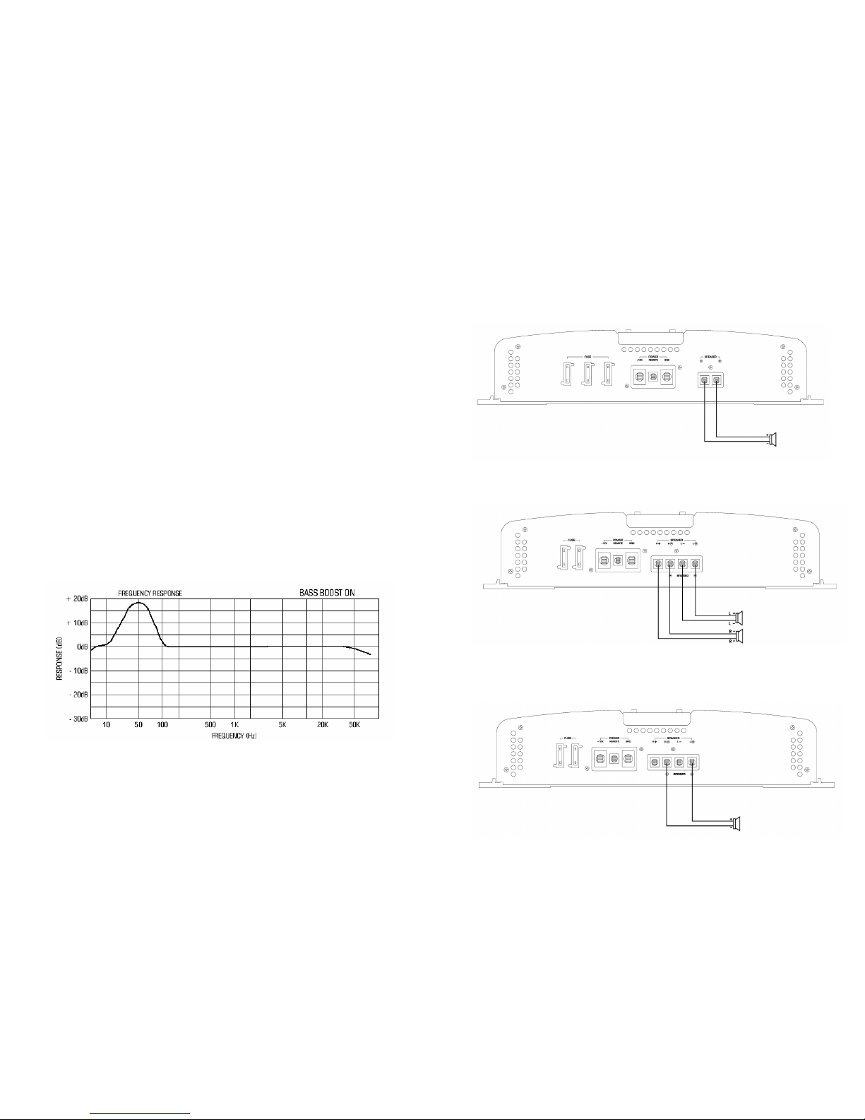
•Variable Bass Boost: By using the variable control, bass notes at 50 Hz are amplified
from 0dB to 18dB depending on the setting of the control. See Tuning your
system for more information on how Bass Boost works.
•Selectable Crossover Switch: Adjust the crossover for your chosen installation
method.
oLPF: Low pass filter-only (40 Hz-250 Hz)
oFULL: No filtering for speakers. For use with an external crossover.
oHPF: High pass filter (40 Hz-250 Hz)
•Variable Low-Pass Filter (40 Hz-250 Hz): For use as a dedicated subwoofer
channel, set filter switch to "LPF". Adjust variable crossover frequency with
control as desired. The amplifier input circuit filters out everything above
40Hz to 250Hz (dependent on the adjustment of the frequency control), so
only the deepest bass notes are amplified.
•Variable High-Pass Filter (40 Hz-250 Hz): For use as a dedicated mid-range
channel, set filter switch to "HPF". The amplifier input circuit filters out
everything below 40Hz to 250Hz (dependent on the adjustment of the
frequency control), so only the deepest mid range notes are amplified.
•Power Indicator LED: This LED will illuminate when the amplifier is turned "ON”.
•Protection Indicator LED: This LED turns on when any of the following occurs:
oAny speaker cable shorted to the vehicles chassis (ground).
oShorted speaker voice coil (zero impedance).
oCombined speaker impedance is too low.(check wiring diagram)
oTurns on due to excessive heat sink temperatures.
•RCA Outputs: These connections are used when connecting additional amplifiers.
-4 -
PLANNING YOUR SYSTEM
•If you plan to expand your system by adding other components sometime in the
future, ensure adequate space is left. If your head unit/source is equipped with Pre-
Amp outputs, it is possible to utilize them to drive this Amplifier.
•Are your component speakers matched? The peak power rating of your speakers
must be equal or greater than the Amplifier’s. Speakers connect to this amplifier
must have a 4 Ohm impedance.
•Consider both the length of your leads, and routing when determining the mounting
location. Pre-Amp input jacks require high quality shielded RCA patch cords.
MOUNTING YOUR SYSTEM
The mounting position of your amplifier will have a great effect on its ability to dissipate the
heat generated during normal operation. The HK Series amplifier has an efficient heat sink for
proper heat dissipation, also integrated with a thermal shutdown (for heat protection) circuit.
Allowing air around the cooling fins will improve heat dissipation dramatically. Do not enclose
the amplifier in a small box or cover it so that air cannot flow around the cooling fins.
Temperatures in car trunks have been measured as high as (158' F) in the summer
time. Since the thermal shut-down point for the Amplifier is (160' F) it must be mounted for
maximum cooling. To achieve maximum convection air flow in an enclosed trunk, mount the
amplifier in a vertical position, on a vertical surface.
Cooling requirements are considerably relaxed when mounting inside the passenger
compartment since the driver will not often allow temperatures to reach a critical point. Floor
mounting under the seat is usually satisfactory as long as there is at least 1 inch (2.54cm) above
the Amplifier's fins for ventilation.
To mount the Amplifier:
1. Use the amplifier as a template to mark the mounting holes.
2. Use extreme caution, inspect underneath surface before drilling.
3. Remove the Amplifier and drill the marked holes.
4. Secure the Amplifier using sheet metal or woods screw (whichever is applicable).

-5 -
ADJUSTMENT & TUNING
The amplifier automatically turns on a few seconds after you turn your vehicle’s ignition
switch to ACC or ON or turn on your auto sound system, depending on how you have wired the
system. The POWER indicator on the amplifier lights illuminates when the amplifier is on.
Important: This amplifier requires 30 amps or more of power from your vehicle’s battery during
operation. To protect your battery from discharging, do not operate the amplifier unless your
vehicle is running.
For the best performance, you must set the input level on the side of the amplifier to adjust the
level of the audio signals that enter the amplifier.
1. Using a small flat screwdriver, turn the input level fully counterclockwise to “MIN”.
2. Turn the auto sound system’s volume control to about one -third of its full range.
3. Adjust the input level (MIN/MAX) to a comfortable listening level.
4. Turn up the auto sound system’s volume control until the sound begins to distort. Then
immediately turn the volume down to a point just before where the distortion began.
5. Adjust the input level until the sound is at the level you want the amplifier to produce.
6. Adjust your head unit’s volume control to a comfortable listening level. Enjoy.
NOTE
Raising the LPF frequency allows higher frequencies to reach the bass speakers while blocking
lower frequencies from midrange speakers. Lowering the Bass frequency allows lower
frequencies to reach the midrange speakers while blocking higher frequencies from bass speakers.
Variable Bass Boost Frequency Response
-6 -
Wiring Diagram
Model: HK-401SX
Mono Load Only
1 Ohm Minimum Load
Models: HK-102SX, HK-302SX
Stereo Mode
0.5 Ohm Minimum Load
Models: HK-102SX, HK-302SX
Mono Mode
1 Ohm Minimum Load

-7 -
Wiring Diagram
Model: HK-204SX
2 Channel Mode (Mono x 2)
1 Ohm Minimum
Model: HK-204SX
3 Channel Mode (Stereo & Mono)
1 Ohm Minimum
Model: HK-204SX
4 Channel Stereo Mode
0.5 Ohm Minimum
-8 -
Wiring Diagram
Model: HK-602SX, HK-802SX
2 Channel Mode (Mono x 2)
0.5 Ohm Minimum
Model: HK-602SX, HK-802SX
1 Channel Mode (Stereo & Mono)
1 Ohm Minimum

-9 -
TROUBLESHOOTING
SYMPTOM
No Sound
CHECK POINT
Is the power LED illuminated?
CURE
1. Check fuses in amplifier.
2. Be sure Turn-on lead is connected
3. Check signal leads.
4. Check gain control.
5. Check Tuner/Deck volume level.
6. Clean contacts on fuse holders.
CHECK POINT
Is the Overload LED illuminated?
CURE
1.Check for speaker short or amplifier overheating.
SYMPTOM
Amp Not Switching On
CHECK POINT
No power to power wire
CURE
Repair power wire or connections.
Check point
No power to remote wire with Head unit on
CURE
Check connections to Head unit.
Check point
Fuse broken
CURE
Replace Fuse
-10 -
TROUBLESHOOTING continued...
SYMPTOM
No Sound in One Channel
CHECK POINT
Check Speaker Leads.
CURE
Inspect for short circuit
Check for open Connection or blown speaker.
CURE
Check Speaker Leads, reverse Left and Right RCA inputs to
determine if problem is occurring before the amp.
SYMPTOM
Amp Turning Off At High Volume
CHECK POINT
Check Speaker load impedance
CURE
Inspect that speaker load impedance recommendations are followed.
Check wiring configuration for speakers is correct.
(To Verify proper load impedance, use an OHM meter to
measure the total load for each channel of the amplifier.)
SYMPTOM
System Protection LED is Lit
CHECK POINT
Temperature Shut-down
CURE
Check for proper air ventilation
Change amplifier location
CHECK POINT
Speaker output shorted
CURE
Check speaker wiring
Check for blown speaker by disconnecting one at a time
and check for LED change.
??Need More Technical Support??
Please Visit
The Technical Support Page at
www.MAAudio.com

-11 -
LIMITED WARRANTY INFORMATION
•Length of Warranty
1 year on Video Products 2 years on Electronic Products 2 years on Speakers
•What is covered
Warranty applies only to MA Audio products sold to consumers by Authorized MA Audio
Dealers in the United States of America or its possessions. Productspurchased by consumers
from Authorized MA Audio Dealer outside of the USA are covered only by that country’s
distributor.
•Who is covered
This warranty covers only the original purchaser of MA Audio product purchased from an
Authorized MA Audio Dealer in the United States. For a list of Authorized Internet Re tail Stores
go to http://www.MAAudio.com. In order to receive service, the purchaser must provide MA
Audio with a copy of the receipt stating the customer name, MA Audio Authorized dealer name,
product purchased and date of purchase. Products found to be defective during the warranty
period will be repaired or replaced (with a product deemed to be equivalent) at MA Audio’s
discretion.
•What is Not Covered
1. Damage caused by accident, abuse, improper operations, water, or theft.
2. Any cost or expense related to the removal or reinstallation of product.
3. Repair Service performed by anyone other than MA Audio’s Repair Department.
4. Any product which has had the serial number defaced, altered, or removed.
5.Any product purchased outside the United States.
6.Any product not purchased from an Authorized MA Audio Dealer.
•Limit on Implied Warranties
Any implied warranties including warranties of fitness for use and merchantability are limited
in duration to the period of the express warranty set forth above. Some states do not allow
limitations on the length of an implied warranty, so this limitation may not apply. No person is
authorized to assume for MA Audio any other liability in connection with the sale of the product.
•How to Obtain Service
1. Please call (310) 223-0400 for MA Audio Customer Service.
Customer Service hours : Monday-Friday, 8am-5pm Pacific Standard Time.
2. Obtain a RA # (Return Authorization Number) from Customer Service.
3. Obtain a “Cashiers Check” or “Money Order” for $9.00 per item for return postage.
(No personal Checks will be accepted)
4. Once you receive your return authorization number from our Warranty Department,
please print this number LARGE on the outside of the packaging.
5. No products will be accepted without a Return Authorization number.
6. Please include the following items with the returned product:
a. Copy of the Original Receipt o f purchase (Required)
b. Cashiers Check or Money Order for $9.00 per item
c. Return Address for shipment.
7. Ship to:
MA Audio
Warranty Department
18601 South Susana Road
Rancho Dominguez, CA 90221
RA#:_______________
-12 -
NOTES

-13 -
WARNING
Investigate the layout of your automobile thoroughly before drilling or cutting any
holes. Use extreme care when you work near the gas tanks, gas or hydraulic lines,
and electrical wiring. Always make sure the power amplifier is securely mounted.
Mounting the amplifier securely to the automobile will prevent damage to the car or
injury to a person, particularly in the event of an accident.
Don’t mount the system so that the wire connections are unprotected or are subject
to pinching or damage from nearby objects.
The +12 VDC power wire must be fused at the battery positive terminal
connection. Before making or breaking power connections at the system power
terminals, disconnect the + 12V wire at the battery. Confirm your head unit and/or
other equipment is turned off while connecting the input RCA jacks and speaker
terminals.
If you need to replace the amplifier fuses, replace it only with a fuse identical to
that supplied with the system. Using a fuse of different type or rating may result in
damage to this system which isn’t covered by the warranty.
This manual suits for next models
5
Table of contents
Other Ma Audio Amplifier manuals