mabe EML27WWF0 User manual

Ingeniería de Servicio
MODEL SERIES:
EML27WWF0 JBS27DILWW EML27NXF0 JBS27RILSS
JCB535DILWW JCB535DILBB JCB535SILSS JCB735DILWW
JCB735DILBB JCB735SILSS JCB835DILWW JCB835SILSS
EML535NNF0 EML535BBF0 EML535NXF0 EML735BBF0
EML735NNF0 EML735NXF0 EML835BBF0 EML835NXF0
Service manual
Ingeniería de Servicio
Important Safety Instructions, Warnings and Recommendations 3
Nomenclature 4
Models 7
Features 8
Tools needed 13
Technical information 14
Installation instructions 15
Using controls 21
List of main components 44
Disassemble and retrofit 45
Electric diagrams 62
Failures and solutions 67
Index
Cocinas eléctricas de
pie libre
Ingeniería de Servicio
IMPORTANT SAFETY NOTICE
The information on this document is directed to
service individuals who possess accurated
knowledge and electrical, electronic and
mechanical experience. Any attempt to repair an
appliance could result in personal injury and
property damage. The manufacturer or seller
could not be held responsible for the
interpretation of this information, nor can it
assume any liability realted to its use.
WARNING
To avoid personal injury, disconnect power
before servicing this product. If electrical power is
required for diagnosis or for the purpose of
testing, disconnect power immediately after
carrying out the necessary checks.
RECONNECT ALL GROUNDING DEVICES
If grounding wires, screws, ribbons, hook, nuts or
washers used to complete a route to the ground
are removed for servicing, they must be returned
to their original position and must be properly
secured.
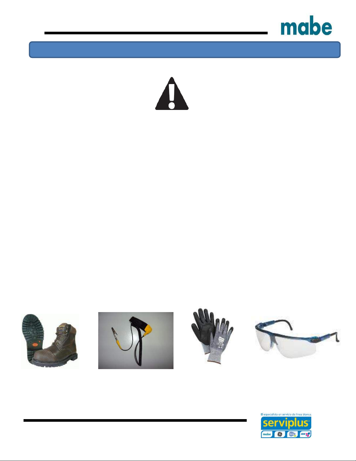
CLOTHING:
Required: Pants, shirt, cap safety shoes to
protect your feet from any sparks or hot metal
particles, do not work with tennis shoes.
Keep clothing free of grease or oil.
Important safety notices, warnings and recommendations
Cocinas eléctricas de pie libre
Ingeniería de Servicio
4
E M L 5 3 5 N N F 0 A
Stove
Brand
M: Mabe
Electric
Feature level
535
735
835
S27
Color
NN: Black/Black
BB: White/White
WW: White/White
Voltage
220/ 240V
Design
Digit
chance
Generation
Digit
chance
Nomenclature
Cocinas eléctricas de
pie libre

Ingeniería de Servicio
5
J B S 2 7 D I L W W
Brand
J: GE
Space
Electric
range
Product type
Code
B: 30"
Feature level
L: 2017
Color
SS: Stainless steel
WW: White
BB: Black
NX: Stainless steel
Autoself
clean
D: Derivative color of BB/WW
R: Stainless with black accents
Voltage
220/ 240V

Ingeniería de Servicio
6
J C B 5 3 5 S I L S S
Brand
J: GE
Fuel type
C: Electric
range
Product type
Code
B: 30"
Feature level
535
735
835
L: 2017
Color
SS: Stainless steel
WW: White
BB: Black
NX: Stainless steel
with black
Voltage
220/ 240V
D: Derivative color of BB/WW
S: Metalic

Ingeniería de Servicio
7
EML27NXF0A
EML27WWF0A
EML535BBF0A
EML535NNF0A
EML535NXF0A
EML735BBF0A
EML735NNF0A
EML735NXF0A
EML835BBF0A
EML835NXF0A
JBS27DIL1WW
JBS27RIL1SS
JCB535DIL1BB
JCB535DIL1WW
JCB535SIL1SS
30" Freestanding electric ranges
4 Coil burners 30" Freestanding electric ranges
4 Radiant burners
EML27NXF0A 12" Dual element
EML27WWF0A
EML535BBF0A 30" Freestanding electric ranges
EML535NNF0A 5 Radiant burners
EML535NXF0A EML735BBF0A True convection air
JBS27DIL1WW EML735NNF0A
JBS27RIL1SS EML735NXF0A EML835BBF0A
JCB535DIL1BB JCB735DIL1BB EML835NXF0A
JCB535DIL1WW JCB735DIL1WW JCB835DIL1WW
JCB535SIL1SS JCB735SIL1SS JCB835SIL1SS
Models
Cocinas eléctricas de
pie libre

Ingeniería de Servicio
8
1. Back protector –seamless design
2. Double oven sensor
3. Triple ring elements
3. Full glass oven door design
4. TrueTemp ™
5. 6.2 Ft^3 Oven capacity
6. Increased usable capacity
7. Six position oven grill
8. Six-pass bake element
9. Full black interior design
10. New oven control design
11. New appereance design
Features
Cocinas eléctricas de
pie libre
Ingeniería de Servicio
9
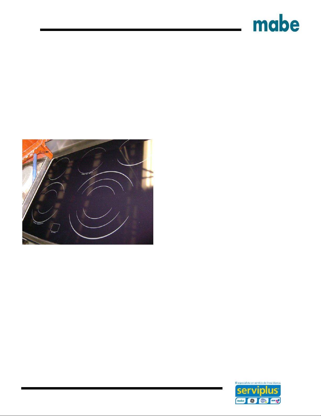
Exclusive cleaning design
As for ease of cleaning, the clean oven interior design conceals the bottom heating element
beneath a steel surface coated with porcelain. All you see es a clean, smooth flat surface.
Convenient new option: Warming area
Maintains soups, sauces, breads and pancakes wam, melts chocolate.
Or use this new burner as you would any other element.
Ingeniería de Servicio
10
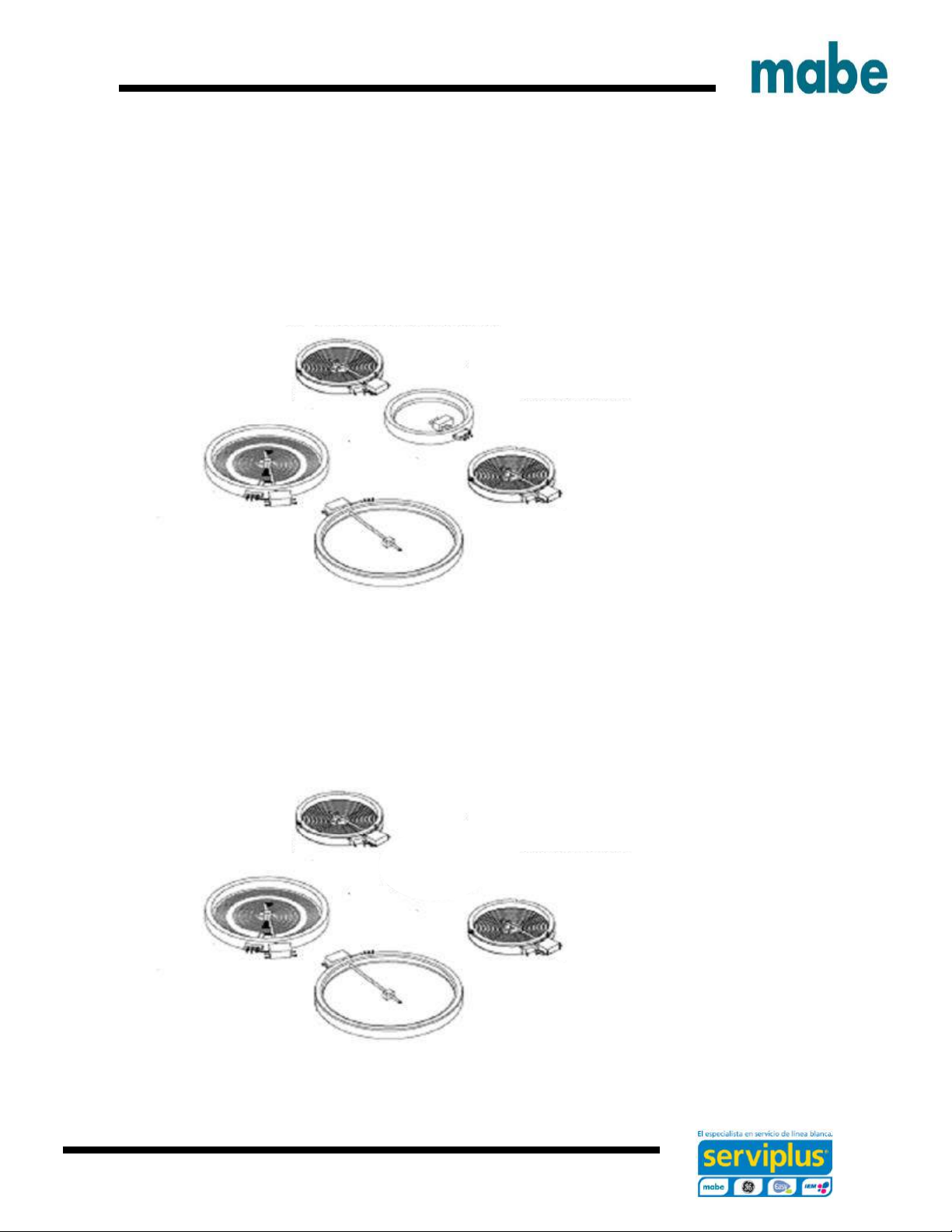
Features of the heating elements
Surface elements
EML835/ JCB835
6" element 240V 1260W
6" element 240V 1260W
6/9" element Warming Zone 6"
9/12" element 240V 2520W
EML735/ JCB735
6" element 240V 1260W
6" element 240V 1260W
8" element Warming Zone 6"
9/12" element 240V 2520W
This manual suits for next models
19
Table of contents
Other mabe Range manuals


