MAC TOOLS EM721 User manual

EM721 Digital Multimeter
To reduce the risk of injury, read and
understand these safety warnings and
instructions before using the tool.
Keep these instructions with the tool
for future reference. If you have any
questions, contact your MAC TOOLS
representative or distributor.
WARNING
Automotive Multimeter
User Manual
EM721

MACTOOLS.COM
2
WARRANTY
This instrument is warranted to be free from defects in material and workmanship for a period of one
year. Our obligation to the original purchaser shall be limited to repairing or replacing, at our expense (not
including shipping charges) a defective tool if returned by the original purchaser within one year from the
date of purchase, all incoming shipping charges prepaid. THIS WARRANTY DOES NOT COVER DEFECTS
OR DAMAGES TO THE TOOL (i) after the warranty period expires; (ii) resulting from misuse or abnormal
operation; (iii) resulting from a failure to properly maintain or operate the tool; or (iv) resulting from any repair
or maintenance services performed by any party other than Mac Tools. This warranty does not cover expandable
items such as batteries and/or fuses.
LIMITATION OF LIABILITY
This manual tells you how to use the meter to perform diagnostic tests and to nd possible locations of
automotive electronic problems. It does not tell you how to correct the problems. Once you have located a
problem, consult your car’s service manual or other manuals to provide specic information needed for repair.
All information, illustrations, and specications contained in this manual are based on the latest information
available at the time of publication. The right is reserved to make changes at any time without notice.
TABLE OF CONTENTS
1. Safety Information.............................................................................. 4
2. Introduction....................................................................................... 7
3. Front panel ........................................................................................ 8
4. Understanding the Display ................................................................ 14
5. Basic Electrical Tests and Measurements ........................................... 17
6. Basic Automotive Measurements........................................................ 26
7. Basic Automotive Diagnostic Testing .................................................. 33
8. Basic Automotive Component Testing ................................................. 58
9. Summary of Automotive Electrical System Tests .................................. 67
10. Specications .................................................................................. 70
11. General Specications ..................................................................... 75
12. Maintenance.................................................................................... 76
13. Meter-PC Communication Software Instruction.................................... 77

800.MACTOOLS
3
METER OVERVIEW
Measurement limits:
DC Voltage 0.1mV to 1000V
AC Voltage 0.001V to 750V
RPM IP 30 to 9000 RPM
RPM IG 60 to 12000 RPM
DC Current (Amperes) 0.1µA to 10A
AC Current (Amperes) 0.1µA to 10A
Resistance (Ohms) 0.1 to 40MΩ
Frequency (Hertz) 0.5Hz to 200kHz
% Duty Cycle 0 to 99.9%
Dwell (Degrees) 0° to 356.4°
Pulse Width (Milliseconds) 0.1ms to 1999.9ms
Temperature (Fahrenheit/Celsius) - 40°F to +2498°F (- 40°C to +1370°C)
Capacitance (Microfarads) 0.001µF to 999µF
Continuity Check Beep at < about 40Ω in the 400Ω range

MACTOOLS.COM
4
1. SAFETY INFORMATION
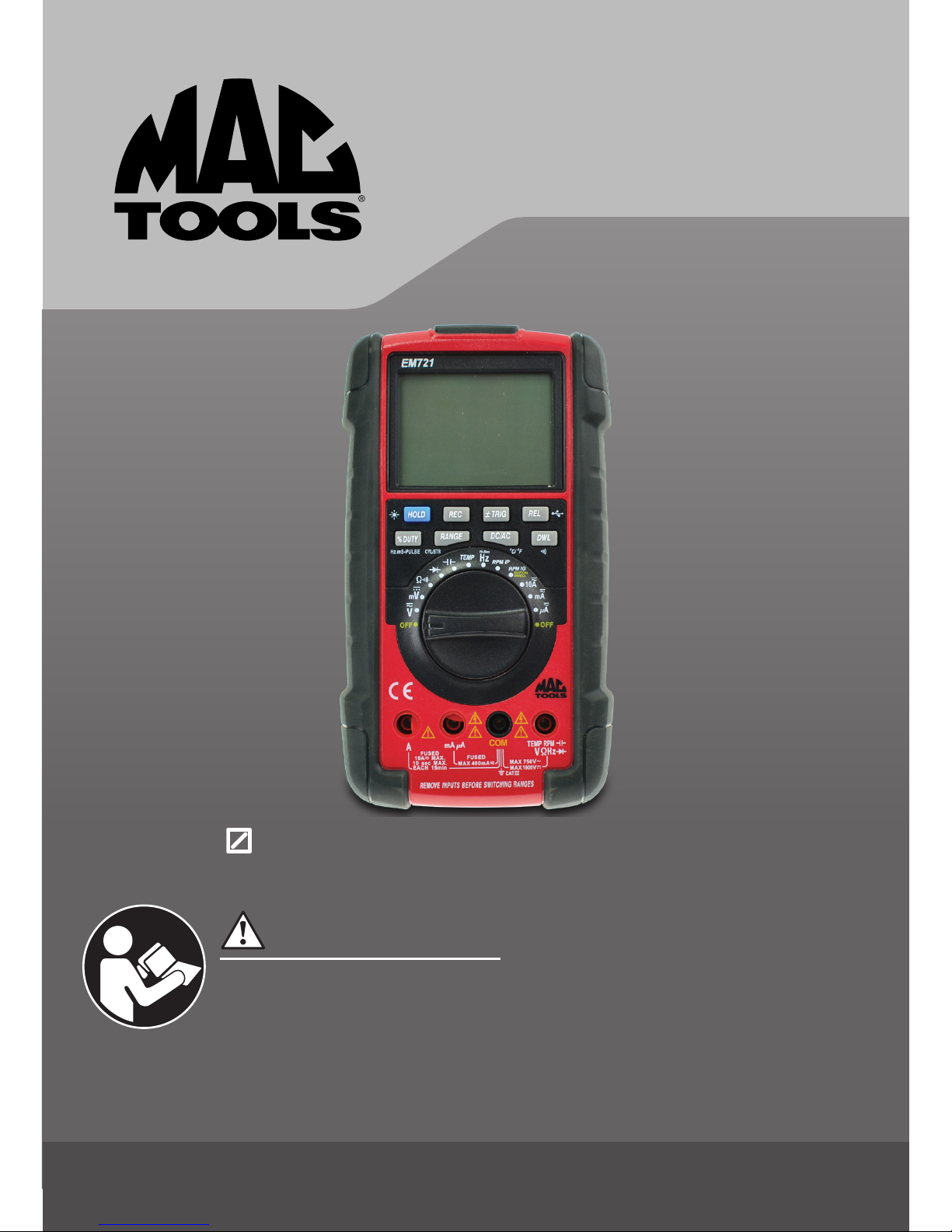
This meter has been designed according to IEC 61010 concerning electronic measuring instruments with a
measurement category (CAT III 1000V) and Pollution Degree 2.
WARNING
TO AVOID POSSIBLE ELECTRIC SHOCK OR PERSONAL INJURY, FOLLOW THESE GUIDELINES:
• Do not use the meter if it is damaged. Before you use the meter, inspect the case.
Pay particular attention to the insulation surrounding the connectors.
• Inspect the test leads for damaged insulation or exposed metal. Check the test leads for continuity.
Replace damaged test leads before you use the meter.
• Do not use the meter if it operates abnormally. Protection may be impaired. When in doubt, have the meter
serviced.
• Do not operate the meter where explosive (or ammable) gas, vapor, or dust is present.
• Do not apply more than the rated voltage, as marked on the meter, between terminals or between any
terminal and earth ground.
• Before use, verify the meter’s operation by measuring a known voltage.
• When servicing the meter, use only specied replacement parts.
• Use caution when working with voltage above 30V ac rms, 42V peak, or 60V dc.
• Such voltages pose a shock hazard.
• When using the probes, keep your ngers behind the nger guards on the probes.
• When making connections, connect the common test lead before you connect the
• live test lead. When you disconnect test leads, disconnect the live test lead rst.
• Remove the test leads from the meter before you open the battery cover or the case.
• Do not operate the meter with the battery cover or portions of the case removed or loosened.
• To avoid false readings, which could lead to possible electric shock or personal injury, replace the battery
as soon as the low battery indicator ( ) appears.
• Do not use the meter in a manner not specied in this manual or the safety features provided by the meter
may be impaired.
• When measuring current using the test leads, turn off circuit power before connecting the meter in the
circuit. Remember to place the meter in series with the circuit.
• To avoid electric shock, do not touch any naked conductor with hand or skin; and do not ground yourself
while using the meter.
• Adhere to local and national safety codes. Individual protective equipment must be used to prevent shock
and arc blast injury where hazardous live conductors are exposed.
• Follow the relevant requirements and safety procedure specied in the users manual and service manual
provided by the manufacturer of the vehicle under test.
• Exhaust gas contains carbon monoxide which is odorless, causes slower reaction time, and can lead to
serious injury. When testing vehicle with the engine running, testing should always be done in a well-
ventilated area or vent exhaust gas outside the building.
• Set the parking brake and block the wheels before testing or repairing the vehicle, unless instructed
otherwise. It’s especially important to block the wheels on front-wheel drive vehicles: the parking brake
doesn’t hold the drive wheels. The ignition orfuel system must always be disabled when performing
starting system tests.
• Always wear safety glasses when working near battery.
• Do not smoke or allow open ames or sparks in the work area. Gasoline fumes and gases produced by
battery are highly explosive.
Keep cigarettes, sparks, and open ames away from batteries at all times.
• To avoid personal injury, do not touch any moving or hot object. Keep body and clothing clear of moving or
hot engine parts at all times.

800.MACTOOLS
5
• Especially in marine applications with inboard or inboard/outboard engines, make sure work area is
well ventilated. Operate bilge blower for at least four minutes before starting engine or making test lead
connections.
• Always avoid working alone.
• Do not use the meter if the meter or your hand is wet.
• Remaining endangerment: When an input terminal is connected to dangerous live potential, it is to be
noted that this potential can occur at all other terminals!
• CAT III - Measurement Category III is for measurements performed in the building installation. Examples
are measurements on distribution boards, circuit breakers, wiring, including cables, bus-bars, junction
boxes, switches, socket-outlets in the xed installation, and equipment for industrial use and some other
equipment, for example, stationary motors with permanent connection to the xed installation. Do not use
the meter for measurements within Measurement Categories IV.
CAUTION
TO AVOID POSSIBLE DAMAGE TO THE METER OR TO THE EQUIPMENT BEING TESTED,
FOLLOW THESE GUIDELINES:
• Disconnect circuit power and discharge all capacitors thoroughly before testing resistance, diode,
capacitor, temperature, and continuity.
• Use the proper terminals, function, and range for your measurements.
• Before measuring current, check the meter’s fuses and turn off power to the circuit before connecting the
meter to the circuit.
• Before turning the rotary switch to change functions, disconnect the test leads from the circuit being tested.

MACTOOLS.COM
6
Symbols
Alternating Current
Direct Current
Both direct and alternating current
Caution, risk of danger, refer to the operating manual before use.
Caution, risk of electric shock.
Earth (ground) Terminal
Fuse
Conforms to European Union directives
The equipment is protected throughout by double insulation or reinforced insulation.

800.MACTOOLS
7
2. INTRODUCTION
The meter is a handheld, battery-operated automotive multimeter. It is a very useful test tool.
This users manual tells you how to use the meter. You may also need a manual that provides technical
information for the vehicle you plan to test. The most important information resources are the vehicle’s service
repair manuals generally available for purchase through automotive dealers. They are also available through a
number of publishers that specialize in providing technical information manuals to independent repair garages.
This users manual servers as a guide to get you started with troubleshooting. You real learning can best be
accomplished through experience. As you become more procient in using this automotive multimeter for
troubleshooting, you will quickly learn how certain electrical symptoms relate to various driveability problems.
Meter Features
• Accurate frequency and pulse measurements with 20,000 count on the high resolution 4000 count display.
• High-speed 41-segment analog bargraph updates 20 times/sec - For nearly seamless real-time accuracy.
• Accurate automotive electronics test and advanced measurements with DC/AC Volts, DC/AC Amps,
Resistance, etc
• Direct reading of dwell without using duty cycle-to-dwell conversion chart when testing electronic fuel
injection, feedback carburetors, and ignition systems
• RPM measurement for automotive engines with 1 to 12 cylinders using the test leads or the inductive
pickup
• mS-pulse width function to test on-time of fuel injectors of both PFI (Port Fuel Injector) and TBI (Throttle
Body Injector) types
• For accurate measurements of RPM, dwell, duty cycle, and mS-pulse width of injectors, the meter provides
seven-step adjustable +/-triggers on 1 to 12 cylinders, either 2- or 4-cycle for outboards, motorcycles, and
conventional engines
• Temperature measurement up to 2,498°F (1,370°C) for catalytic converters, fan switch, etc.
• Capacitance and non-automotive frequency measurement
• Back-lighted display
• USB communication

MACTOOLS.COM
8
3. FRONT PANEL
14
891011
1
5
6
16
12
13
3
2
4
15
7
1. Digital Display
Digital readings are displayed on a 4,000 count display with polarity indication and automatic decimal
point placement. When this meter is turned on, all display segments and symbols appear briey during
aself test.

800.MACTOOLS
9
2. Analog Bargraph
The bargraph provides an analog representation of readings and updates 20 times per second. The 2×41
segment bargraph illuminates from left to right as the input increases. The bargraph is easier to read when
the data causes the digital display to rapidly change. It is also useful for trend setting or directional data.
The bargraph also indicates the trigger level.
3. “±TRIG “Button
This “±TRIG” button can be used to toggle between negative (-) and positive (+) trigger slope and adjust
trigger level.
When the meter is in RPM, duty cycle, pulse width, frequency (automotive Hz) or dwell measurement
function, hold down the “±TRIG” button for one second to toggle between negative (-) and positive (+)
trigger slope. The slope is indicated by the + or - sign next to “TRIG” in the lower-left corner of the display.
The meter defaults to negative (-) trigger slope. Once the trigger slope is selected, press the “±TRIG” button
repeatedly to adjust trigger level if the meter reading is too high or unstable.
The trigger level adjustment has seven steps. Press the “±TRIG” button to move one step at a time to select
a suitable trigger level.
TRIGGER STEP
Voltage Level
(RPM, Duty Cycle, mS,
Hz (automotive), Dwell)
Approximate Trigger Level
as Indicated by Bargraph
+4 +8.2V
+3 +6.8V
+2 +3.2V
+1 +1.4V
-1 -1.4V
-2 -3.2V
-3 -6.8V

MACTOOLS.COM
10
4. “REL” Button
Used to enter or exit Relative mode as well as to turn on or off the USB communication function.
Press this “REL” button to enter Relative mode. The meter stores the present reading as a reference for
subsequent measurements. “ ” appears as a Relative mode indicator, and the display reads zero.
In Relative mode, when you perform a new measurement, the display shows the difference between the
reference and the new measurement.
To exit the Relative mode, just press the “REL” button again. “ ” disappears.
Note: • The meter enters manual range mode when you enter the Relative mode.
• When you use Relative mode, the actual value of the object under test must not exceed the full-
range reading of the selected range. Use a higher measurement range if necessary.
• Relative mode is not available in diode and continuity test functions.
Press and hold down this “REL” button for 1 second to turn on the USB communication function, “ ”
will appear on the display as an indication. To turn off the USB communication function, press and hold
down this “REL” button for 1 second again. “ ” disappears.
5. “DWL” Button
This “DWL” button can be used to select dwell measurement function or switch between resistance and
continuity test functions.
When the meter is in RPM IG function, you can press this “DWL” button to select dwell measurement
mode; “DWL°” will appear on the display as an indication. Dwell is the number of degrees of distributor
rotation where the points remains closed. Dwell can be measured for 1 to 12 cylinders. The conversion
between duty cycle and dwell can be obtained using the following formula:
% Duty Cycle = Dwell (in degrees) × No. of Cylinders × 100%
360 degrees
Dwell = 360 degrees ×% Duty Cycle
No. of Cylinders 100%
When the meter is in the dwell function, you can press the “DWL” button again or the “% DUTY” button to
return to the function the meter was in just before entering dwell function.
When the rotary switch is in the “Ω ” position, you can press the “DWL” button to switch between
resistance and continuity test functions. A continuity test can be used to verify that you have a closed
circuit. The continuity function detects opens and shorts lasting as little as 100 milliseconds. In the 400Ω
range, resistance of less than about 40Ω causes the built-in buzzer to sound. This can be a valuable
troubleshooting aid when looking for intermittent faults associated with connections, cables, relays,
switches, etc.

800.MACTOOLS
11
6. “DC/AC” Button
Used to switch between DC and AC function or between °C and °F.
When the rotary switch is in “ “, “10 “, “m ” or “μ ” position, you can press this “DC/AC” button to
switch between DC and AC function; when AC function is selected, “ ” will appear on the display as an
indication; when DC function is selected, “ ” will appear on the display as an indication.
You can press the “DC/AC” button to switch between °C and °F when the rotary switch is in “TEMP”
position. When Celsius temperature measurement is selected, “°C” will appear on the display as an
indication; and when Fahrenheit temperature measurement is selected,“°F” will appear on the display as
an indication.
7. Rotary Switch
Following functions are selected by setting the rotary switch:
Switch
Position Function
Volts DC/AC
mMillivolts DC only
ΩResistance/Continuity test (Ohms)
Diode test
Capacitance (Microfarads)
TEMP Temperature (Fahrenheit and Celsius)
Frequency (non-automotive frequency) measurement (Hertz)
RPM measurement on 2- or 4-stroke engines using the Inductive Pickup on a
spark plug wire.
RPM measurement on 1 to 12 cylinder engines using the test leads in the
primary side of the ignition coil and Duty Cycle, Pulse Width, Hz (automotive),
and Dwell measurement.
10 Current (Amperes) DC/AC
mCurrent (Milliamperes) DC/AC
μCurrent (Microamperes) DC/AC
OFF Turns off the meter
8. “ ” Terminal
Input terminal for voltage, resistance, continuity, RPM, diode, frequency, capacitance, temperature, duty
cycle, pulse width and dwell measurements.

MACTOOLS.COM
12
9. “COM” Terminal
Common (return) terminal for all measurements.
10. “mA μA” Terminal
Input terminal for current measurements < 400mA.
11. “A” Terminal
Input terminal for current measurements between 400mA and 10A.
12. “RANGE” Button
This “RANGE” button can be used to:
• Toggle between autorange mode and manual range mode as well as to select desired manual range.
• Select number of cylinders (1, 2, 3, 4, 5, 6, 8, 10, or 12) to match the engine when the meter is in
RPM IG or dwell function.
• Toggle between 2-Cycle engine (or distributorless ignition system 4-Cycle engine) and 4-Cycle engine
when the meter is in RPM IP function.
In a function which has both autorange mode and manual range mode, the meter defaults autorange mode
and “ ” appears on the display as an indication. You can press the “RANGE” button to enter manual
range mode, “ ” will disappear and the meter will stay in the present range.
In manual range mode, you can press the “RANGE” button to select the next higher range. After the highest
range, the meter wraps to the lowest range. To exit manual range mode and return to autorange mode,
press and hold down the “RANGE” button for 1 second; “ ” will appear on the display as an indication.
Always select a range higher than you expect the current or voltage to be. Then select a lower range if
better accuracy is needed. If the range is too high, the readings are less accurate. If the range is too low,
the meter shows “OFL” as an overload indication.
When the meter is in the RPM IG or dwell function, press the “RANGE” button to toggle between 1, 2, 3, 4,
5, 6, 8, 10, 12 cylinder engines. The selected number of cylinders is indicated by the number preceding
CYL on the display.
When the meter is in the RPM IP function, press the “RANGE” button to toggle between 2-cycle engine
(or distributorless ignition system 4-cycle engine) and 4-cycle engine; the selected number of cycles (or
strokes) is indicated by the corresponding symbol (“ ” or “ ”).
13. “% DUTY” Button
When the meter is in RPM IG function, press this “% DUTY” button to measure duty cycle (or duty factor)
in percent; % readout is displayed. Duty cycle is the percentage of time a signal is above or below a trigger
level during one cycle.

800.MACTOOLS
13
To select pulse width function, press the “% DUTY” button again; mS readout is displayed. Pulse width is
the length of time an actuator is energized. For example, fuel injectors are activated by an electronic pulse
from the Engine Control Module. This pulse generates a magnetic eld that pulls the injector nozzle valve
open. The pulse ends and the injector nozzle is closed. This Open-to-Closed time is the pulse width and is
measured in milliseconds (mS)
To select the frequency function, press the “% DUTY” button once more; Hz readout is displayed.
Frequency is the number of cycles a signal completes each second.
You can step through RPM, duty cycle, pulse width, and frequency by pressing this “% DUTY” button.
When the rotary switch is in the “RPM IG” position, you can press the “DWL” button to select dwell
measurement function; “DWL°” will appear on the display as an indicatior for the dwell measurement
function.
When in dwell measurement function, you can press the “DWL” button again or the” % DUTY” button to go
back to the previous function from which the meter entered the dwell measurement function.
14. “HOLD” Button
Used to enter or exit Hold mode as well as to turn on or off the backlight.
Press this “HOLD” button to enter the Hold mode. “ ” appears on the display as an indication and the
meter holds the present reading on the display. In the Hold mode, whenever meter detects a new stable
reading, the meter sounds a beep and displays the new stable reading. To exit the Hold mode, press the
“HOLD” button again. “ ” disappears.
Note: When the meter is in the Recording or Relative mode, the Hold function simply freezes the present
reading and will not update the the display with new stable reading.
To turn on or off the backlight, press and hold down this “HOLD” button for 1 second.
15. “REC” Button
Press the “REC” button to enter the Recording mode, “ ” will appear on the display as an indication.
(The meter will exit autorange mode automatically and stay in the present range when it enters Recording
mode.) This function allows you to record maximum, minimum, and average values for a series of
measurements in the same function and range. This meter beeps each time a new maximum or minimum
value is recorded. Press the “REC” button to scroll through the stored maximum, minimum, and average
values. When an overload is captured, a beeper tone is emitted and the meter displays “OFL” as an overload
indication. The meter can only record for 24 hours in this mode.
Note: In diode or continuity function, the Recording mode is not available.
16. USB Port

MACTOOLS.COM
14
Auto Power Off
When the rotary switch is in the position, the meter will turn off automatically if you have not operated the
meter for about 30 minutes (1 hour in the Recording mode) while the input voltage is less than 1V.
When the rotary switch is in other position, the meter will turn off automatically if you have not operated the
meter for about 30 minutes (1 hour in the Recording mode).
About 30 seconds before the meter turns off automatically, the symbol “ ” will start ashing to remind you
that the meter will turn off.
To turn on the meter again, set the rotary switch to OFF position rst and then set it to a desired position.
To disable the automatic power-off feature, turn on the meter while holding down the “HOLD” button.
Using Inductive Pickup
The meter comes with an Inductive Pickup. The Inductive Pickup takes the magnetic eld generated by the
current in the spark plug wire and converts it to a pulse that triggers the meter’s RPM measurement.
4. UNDERSTANDING THE DISPLAY
12567891011121314
15
16
17
18
19
20
22
23
24
25
26
34
21

800.MACTOOLS
15
1. . Displayed when the RPM IG mode is selected. In this mode, revolutions per minute on 1 to
12cylinder engines can be measured using the test leads on the primary side of the ignition coil.
2. . Displayed when the RPM IP mode is selected. In this mode, revolutions per minute on 2- or
4-stroke engines can be measured using the Inductive Pickup on a spark plug wire.
3. . Displayed when dwell mode is selected.
4. . Displayed when duty cycle mode is selected.
5. 18 . Displayed when a certain number of cylinders is selected in the RPM IG or Dwell mode. Press the
“RANGE” button to toggle between 1, 2, 3, 4, 5, 6, 8, 10, 12 cylinder engines.
6. . Displayed when 4 strokes are selected in the RPM IP mode. Press the “RANGE” button to toggle
between 2-stroke and 4-stroke engines.
7. . Displayed when 2 strokes are selected in the RPM IP mode. Press the “RANGE” button to toggle
between 2-stroke and 4-stroke engines.
8. . Indicates that the value being displayed is the average of all readings taken since the Recording mode
was entered.
9. . Displayed when diode test is selected.
10. . Displayed when Relative mode is active.
11. . Displayed when Recording mode is active.
12. . Displayed when continuity test is selected.
13. . Displayed when the Hold mode is active.
14. . Displayed when the battery is low.
WARNING
TO AVOID FALSE READINGS, WHICH COULD LEAD TO POSSIBLE ELECTRIC SHOCK OR PERSONAL
INJURY, REPLACE THE BATTERY AS SOON AS THIS LOW BATTERY INDICATOR APPEARS.
15. .Indicates that the value being displayed is the maximum reading taken since the Recording mode
was entered.
16. . Displayed when autorange mode is active.
17. . Indicates that the value being displayed is the minimum reading taken since the Recording mode was
entered.
18. . Displayed when DC measurement function is selected.
19. . Displayed when AC measurement function is selected.
20. . Indicates negative readings. In Relative mode, this sign indicates that the present input is less than
the stored reference.
21. . Indicates that the automatic power-off feature has been enabled.
22. . Indicates that USB communication function has been turned on.
23. .Displayed when a – or + trigger slope is selected while the meter is in the RPM IP or RPM IG (Duty
Cycle, Pulse Width, Hz or Dwell) mode. The meter defaults to a – (negative) trigger slope. Press the “±
TRIG” button for 1 second to toggle between negative (-) and positive (+) trigger slope. Also displayed
when the bargraph indicates trigger level.

MACTOOLS.COM
16
24. . Indicates the polarity of the input.
Also indicates a – (negative) or + (positive) trigger slope when a trigger slope is selected.
HIGH TIME
LOW TIME
1 DUTY CYCLE
Select a negative (-) trigger slope to measure low (-) time and a positive (+) trigger slope to measure high
(+) time. For example, when measuring duty cycle of the Mixture Control Solenoid, the low (-) time is the
On time in most cases.
25. ANALOG DISPLAY SCALE. Displayed with 41-position analog pointers.
26. The following symbols indicate the unit of the value displayed:
DWL° The number of degrees of distributor rotation where the points remain closed,
measured for 1 to 12 cylinders
% Percent, used for duty cycle measurement
°C/°F Centigrade or Fahrenheit temperature measurement
Ω Ohms
kΩ
Hertz (1 cycle/sec)
Kilohertz (1 × 10 cycles/sec)
Volts
Millivolts (1 × 10 Volts)
Amperes (Amps)
Milliamperes (1 × 10 Amps)
Microamperes (1 × 10 Amps)
Microfarads (1 × 10 Farads)
Milliseconds (1 × 10 seconds)
Megohm (1 × 10 Ohms)
6
3
-3
-3
-6
-6
-3
3
Kilohm (1 × 10 Ohms)
MΩ
Hz
kHz
V
mV
A
mA
µA
µF
mS

800.MACTOOLS
17
5. BASIC ELECTRICAL TESTS AND MEASUREMENTS
One of the most common electrical diagnostic tools is a digital multimeter (DMM). A DMM is simply an
electronic yardstick for making electrical measurements.
DMMs have many special functions and features, but the most common use is to measure voltage, current, and
resistance. An automotive multimeter such as this automotive multimeter can also measure frequency, RPM,
duty cycle, dwell, pulse width, temperature, capacitance, and even the condition of diodes.
General Considerations for Making Measurements
• Accuracy
A measurement range determines the highest value the meter can measure. Most Meter functions
have more than one range. When making a measurement, it is very important that you are in the right
measurement range. Selection of a lower range moves the decimal point one place to the left and increases
the accuracy of the readings. When the LCD shows OFL (overload), the range is too low; select the next
higher range.
• Analog Bargraph
The bargraph is useful for trend setting or directional data. It is easiest to read when the data causes the
digital display to change rapidly.
• Safety Shutter
When measuring voltage, be sure that the red test lead is connected to the
“ ” input jack; if the red test lead is connected to the “A” or “mA μA” jack, you may be injured or the
meter may be damaged. When measuring current, do not connect the red test lead to the “ ” input
jack. The safety shutters of the meter areused to prevent inadvertent connection to wrong input terminal.
Voltage Measurements
Voltage measurements are dynamic tests that measure the voltage across a circuit or component with the power
on. Voltage measurements are made with the test leads connected across the circuit element under test.
WARNING
TO AVOID ELECTRICAL SHOCK AND INSTRUMENT DAMAGE, INPUT VOLTAGE MUST NOT EXCEED
1000V DC OR 750V AC RMS. DO NOT ATTEMPT TO MEASURE ANY UNKNOWN VOLTAGE THAT
MAY EXCEED 1000V DC OR 750V AC RMS.
NOTE: When making voltage measurement, this meter must be connected in parallel with the circuit or circuit
element under test.

MACTOOLS.COM
18
Blac
kR
ed
Parallel Connection
12V Battery
Meter setup to measure voltage:
• Set the rotary switch to the voltage ( or m ) setting. (The m setting is only for DC millivolt
measurements.)
• Press the “DC/AC” button to select AC or DC voltage measurement, the display will show the corresponding
symbol.
• Insert the black lead in the “COM” jack.
• Insert the red lead in the “ ” jack.
Connect:
Back probe to the negative (-) circuit or to ground.
Red probe to the circuit coming from the power source.
Resistance Measurements
Resistance is a static measurement which means that it must be measured with the power off. It is measured in
Ohms (Ω) and the values can vary greatly from a few milliohms (mΩ) for contact resistance to billions of ohms
for insulators.
WARNING
TURN OFF POWER AND DISCHARGE ALL CAPACITORS IN THE CIRCUIT TO BE TESTED BEFORE MAKING
IN-CIRCUIT RESISTANCE MEASUREMENTS. ACCURATE MEASUREMENT IS NOT POSSIBLE IF EXTERNAL
OR RESIDUAL VOLTAGE IS PRESENT.
NOTE: The resistance in the test probes can affect accuracy in the 400 range. Short the probes together and
press the “REL” button to subtract test lead resistance from the measurement.

800.MACTOOLS
19
RedBlack
Parallel Connection
Meter setup to measure resistance:
• Set the rotary switch to the Ω setting. The meter defaults to resistance measurement function.
• If a more accurate measurement is desired, select the proper resistance range by pressing the “RANGE”
button.
• Insert the black lead in the “COM” jack.
• Insert the red lead in the “ ” jack.
Connect:
• Test probes across the resistor or circuit to be tested.
Accuracy:
Rapidly changing display readings (noise) can sometimes be eliminated if you change to a higher range. You
can also smooth out noise somewhat by using the averaging (AVG) feature provided by the Recording function.
Continuity Test
A continuity test is a static test (circuit power off) that allows you to quickly and easily distinguish between
an open and a closed circuit. When the meter detects a closed circuit or short, it beeps so you do not have to
look at the meter during the test. This can be a valuable troubleshooting aid when determining good or blown
fuses and fusible links, open or shorted conductors and wires, operations of switches, etc. It is also helpful for
troubleshooting in out-of-the-way locations where it is difcult to watch the readout at all times.
NOTE: Turn off power to the circuit to be tested.
A beeper tone does not necessarily means zero resistance.

MACTOOLS.COM
20
RedBlack
OPEN CIRCUIT - NO BEEP
Meter setup to test circuit continuity:
• Set the rotary switch to the Ω setting.
• Press the “DWL” button until “ ” appears on the display. Now the meter is in continuity test function and
the meter defaults to the 400Ω range.
• Insert the black lead in the “COM” jack.
• Insert the red lead in the “ ” jack.
Connect:
• Test probes across the circuit to be tested.
If the circuit is closed (resistance < about 40Ω), the meter will beep. If the circuit is open (resistance > 150Ω),
there is no beep.
RedBlack
CLOSED CIRCUIT - BEEP SOUNDS
Table of contents
Languages:
Other MAC TOOLS Multimeter manuals