506/506B EN
Read First
Safety Information
WARNING
Understand and follow operating instructions carefully.
Use the meter only as specied in this manual; otherwise,the
protection provided by the meter may be impaired.
This identies hazardous conditions and actions that could
cause BODILY HARM or DEATH. To avoid possible danger,
follow below guidelines.
• Use the meter only as specied in this manual or the
protection by the meter might be impaired.
• Never operate the meter with the cover removed or the
case open.
• To avoid false readings that can lead to electric shock and
injury, replace battery as soon as low battery indicator.
• Use caution with voltages above 30VAC rms, 42VAC peak,
or ±30VDC. These voltages pose a shock hazard.
• When using test leads or probes, keep your ngers behind
the nger guards.
• Remove test lead from meter before opening the battery
door or meter case.
• Always use proper terminals, switch position, and range for
measurements.
• Do not apply more than the rated voltage, as marked on
meter, between terminals or between any terminal and
earth ground.
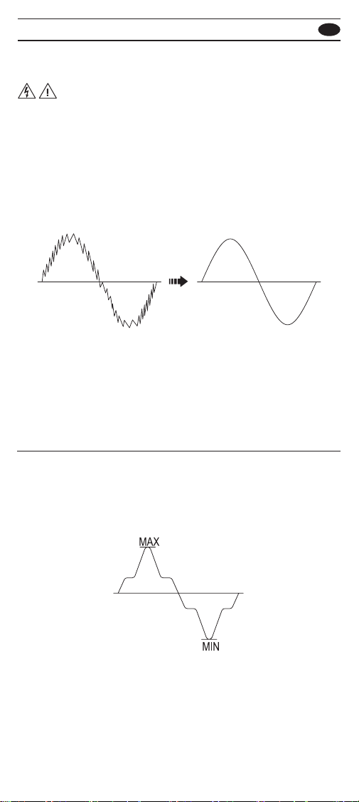
• Do not use the High Frequency Rejection (Low Pass
Filter) option to verify the presence of hazardous voltages.
Voltages greater than what is indicated may be present.
First, make a voltage measurement without the lter to
detect the possible presence of hazardous voltage. Then
select the lter function.
• To avoid possible electric shock or personal injury, never
attempt an in-circuit current measurement where the open
circuit potential to earth is greater than 1000V.
• Replace the fuse as soon as the indicator (FUSE) appears.
• Only replace the blown fuse with the proper rating as
specied in this manual.
• Do not use the meter around explosive gas, vapor or dust.
• To reduce the risk of re or electric shock do not expose
this product to rain or moisture.