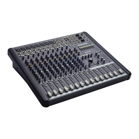
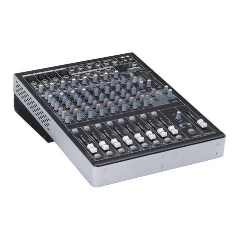
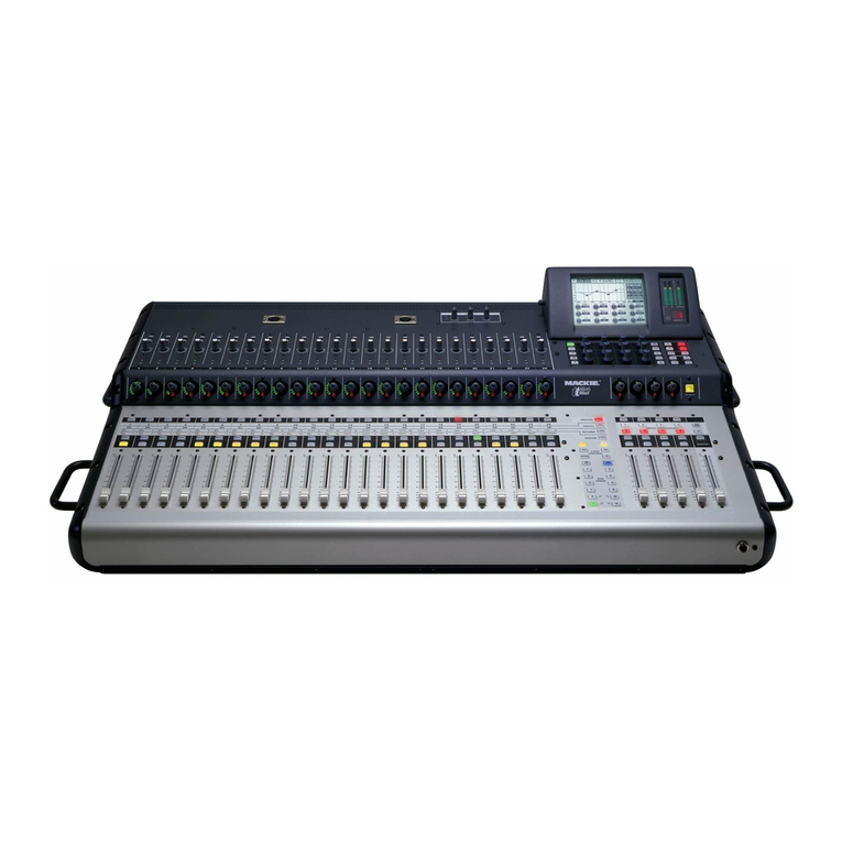
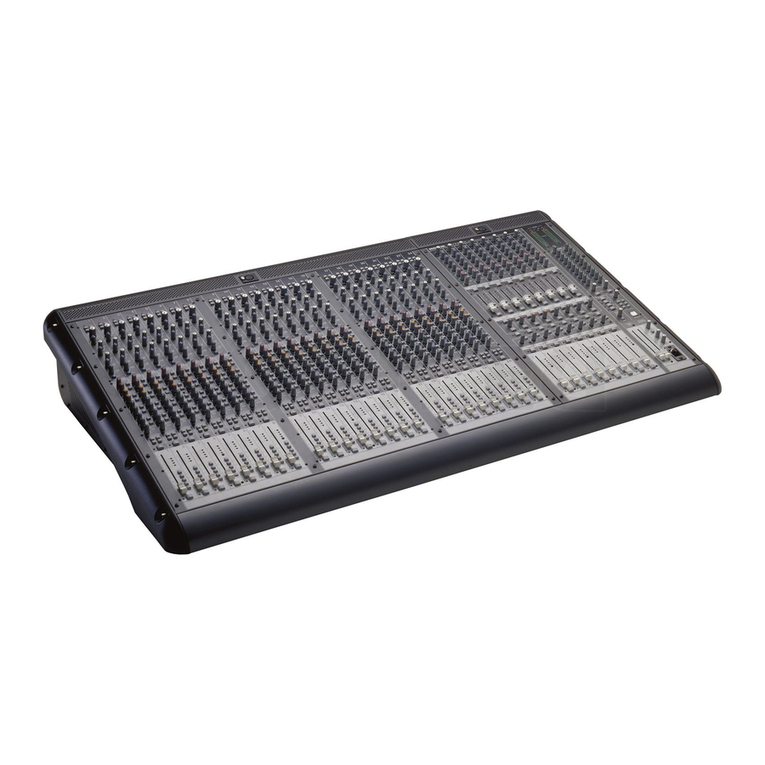
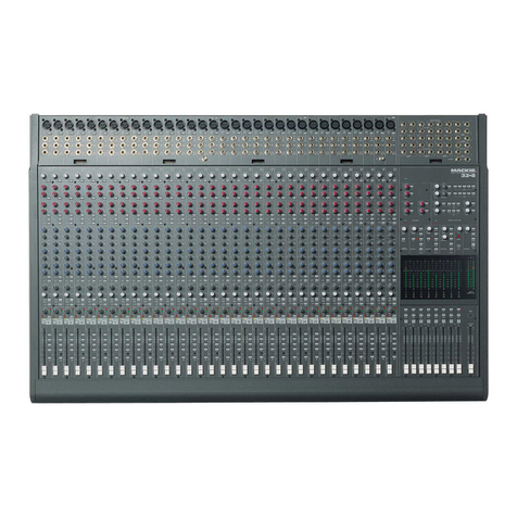
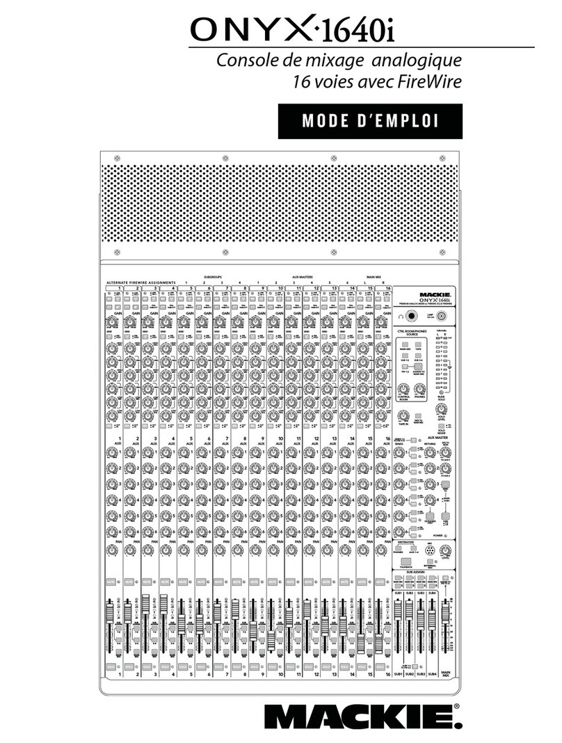
Mackie VLZ4 User manual

VLZ4 4•Bus
OWNER’S MANUAL
24-/32-Channel 4-Bus FX Mixer with USB
POWER
ON
PHANTOM
ON
3 2 1 2 1
2 1
6 5 4
3 2 16 5 4
3 2 14
SUBGROUP OUTS
BAL / UNBAL
SUBGROUP INSERTS
TIP SEND, RINGRETURN
AUX INSERTS
TIP SEND, RING RETURN
AUX SENDS
BAL / UNBAL
3 2 14
L
R
MONO
L
R
MONO
STEREO RETURNS
BAL / UNBAL
31/32 29/30
BAL / UNBALBAL / UNBAL
MONITOR
MONO
MONITOR
L
R
100 - 240 V
50 - 60 Hz 55W
TALKBACK
MIC
RIGHT MAIN OUT
INSERT LINE
LEFT MAIN OUT
INSERT LINE
MONO MAIN OUT
INSERT LINE
LEVEL
OUTPUT LUSB
R
L
R
TAPE
OUTIN
TIP SEND
RING RETURN
TIP SEND
RING RETURN
TIP SEND
RING RETURN
BAL / UNBAL BAL / UNBAL BAL / UNBAL
20
202122232425262728
20
19
19
19
18
18
18
17
17
17
16
16
16
15
15
15
14
14
14
13
13
13
12
12
12
11
11
11
10
10
10
9
9
9
8
8
8
7
7
7
6
6
6
5
5
5
4
4
4
3
3
3
2
2
2
1
1
1
21
21
22
22
23
23
24
24
25
25
26
26
27
27
28
28
ONYX MIC PREAMPS
LINE (BAL / UNBAL)
INSERTS (TIP SEND, RING RETURN)
LINE (BAL / UNBAL)
INSERTS (TIP SEND, RING RETURN)
ONYX MIC PREAMPS
UNBALANCED
REVISION
SERIAL NUMBER
REPLACEWITH THE SAME TYPE FUSE AND RATING.
DISCONNECTSUPPLY CORD BEFORE CHANGING FUSE
UTILISEUN FUSIBLE DE RECHANGE DE MÊME TYPE.
DEBRANCHERAVANTDE REMPLACER LE FUSIBLE
WARNING:
TOREDUCE THE RISK OF FIRE OR ELECTRIC
SHOCK,DO NOT EXPOSE THIS EQUIPMENTTO RAIN OR
MOISTURE. DO NOT REMOVE COVER.NO USER SERVICEABLE
PARTSINSIDE.REFER SERVICING TO QUALIFIED PERSONNEL.
AVIS:
RISQUEDE CHOC ELECTRIQUE — NE PAS OUVRIR
THIS DEVICE COMPLIES WITH PART 15 OF THE FCC RULES FOR THE U.S. AND THE ICES-003 FOR
CANADA. OPERATION IS SUBJECT TO THE FOLLOWING TWO CONDITIONS: (1) THIS DEVICE MAY
NOT CAUSE HARMFUL INTERFERENCE, AND (2) THIS DEVICE MUST ACCEPT ANY INTERFERENCE
RECEIVED, INCLUDING INTERFERENCE THATMAY CAUSE UNDESIRED OPERATION.
+6
U

2
VLZ4 4•Bus
1. Read these instructions.
2. Keep these instructions.
3. Heed all warnings.
4. Follow all instructions.
5. Do not use this apparatus near water.
6. Clean only with a dry cloth.
7. Do not block any ventilation openings. Install in accordance with the
manufacturer’s instructions.
8. Do not install near any heat sources such as radiators, heat registers,
stoves, or other apparatus (including amplifiers) that produce heat.
9. Do not defeat the safety purpose of the polarized or grounding-type
plug. A polarized plug has two blades with one wider than the other.
A grounding-type plug has two blades and a third grounding prong.
The wide blade or the third prong are provided for your safety. If the
provided plug does not fit into your outlet, consult an electrician for
replacement of the obsolete outlet.
10.
Protect the power cord from being walked on or pinched particularly at
plugs, convenience receptacles, and the point where they exit from the
apparatus.
11.
Only use attachments/accessories specified by the manufacturer.
12.
Use only with a cart, stand, tripod, bracket, or
table specified by the manufacturer, or sold with
the apparatus. When a cart is used, use caution
when moving the cart/apparatus combination to
avoid injury from tip-over.
13.
Unplug this apparatus during lightning storms or
when unused for long periods of time.
14.
Refer all servicing to qualified service personnel. Servicing is required
when the apparatus has been damaged in any way, such as power-
supply cord or plug is damaged, liquid has been spilled or objects have
fallen into the apparatus, the apparatus has been exposed to rain or
moisture, does not operate normally, or has been dropped.
15.
This apparatus shall not be exposed to dripping or splashing, and no
object filled with liquids, such as vases or beer glasses, shall be placed
on the apparatus.
16.
Do not overload wall outlets and extension cords as this can result in a
risk of fire or electric shock.
17.
This apparatus has been designed with Class-I construction and must
be connected to a mains socket outlet with a protective earthing
connection (the third grounding prong).
18.
This apparatus has been equipped with a rocker-style AC mains power
switch. This switch is located on the rear panel and should remain
readily accessible to the user.
19.
The MAINS plug or an appliance coupler is used as the disconnect
device, so the disconnect device shall remain readily operable.
PORTABLE CART
WARNING
20.NOTE: This equipment has been tested and found to comply
with the limits for a Class B digital device, pursuant to part 15
of the FCC Rules. These limits are designed to provide reasonable
protection against harmful interference in a residential installation.
This equipment generates, uses, and can radiate radio frequency
energy and, if not installed and used in accordance with the
instructions, may cause harmful interference to radio communications.
However, there is no guarantee that interference will not occur
in a particular installation. If this equipment does cause harmful
interference to radio or television reception, which can be determined
by turning the equipment off and on, the user is encouraged to try to
correct the interference by one or more of the following measures:
• Reorientorrelocatethereceivingantenna.
• Increasetheseparationbetweentheequipmentandthe
receiver.
• Connecttheequipmentintoanoutletonacircuitdifferentfrom
that to which the receiver is connected.
• Consultthedealeroranexperiencedradio/TVtechnicianfor
help.
CAUTION: Changes or modifications to this device not expressly
approved by LOUD Technologies Inc. could void the user's authority to
operate the equipment under FCC rules.
21.
This apparatus does not exceed the Class A/Class B (whichever is
applicable)
limits for radio noise emissions from digital apparatus as
set out in the radio interference regulations of the Canadian Department
of Communications.
ATTENTION — Le présent appareil numérique n’émet pas de bruits
radioélectriques dépassant las limites applicables aux appareils
numériques de class A/de class B (selon le cas) prescrites dans le
réglement sur le brouillage radioélectrique édicté par les ministere des
communications du Canada.
22.
Exposure to extremely high noise levels may cause permanent hearing
loss. Individuals vary considerably in susceptibility to noise-induced
hearing loss, but nearly everyone will lose some hearing if exposed to
sufficiently intense noise for a period of time. The U.S. Government’s
Occupational Safety and Health Administration (OSHA) has specified
the permissible noise level exposures shown in the following chart.
According to OSHA, any exposure in excess of these permissible limits
could result in some hearing loss. To ensure against potentially
dangerous exposure to high sound pressure levels, it is recommended
that all persons exposed to equipment capable of producing high
sound pressure levels use hearing protectors while the equipment
is in operation. Ear plugs or protectors in the ear canals or over the
ears must be worn when operating the equipment in order to prevent
permanent hearing loss if exposure is in excess of the limits set forth
here:
Important Safety Instructions
CAUTION AVIS
RISK OF ELECTRIC SHOCK. DO NOT OPEN
RISQUE DE CHOC ELECTRIQUE. NE PAS OUVRIR
CAUTION: TO REDUCE THE RISK OF ELECTRIC SHOCK DO NOT REMOVE COVER (OR BACK)
NO USER-SERVICEABLE PARTS INSIDE. REFER SERVICING TO QUALIFIED PERSONNEL
ATTENTION: POUR EVITER LES RISQUES DE CHOC ELECTRIQUE, NE PAS ENLEVER LE COUVERCLE.
AUCUN ENTRETIEN DE PIECES INTERIEURES PAR L'USAGER.
CONFIER L'ENTRETIEN AU PERSONNEL QUALIFIE.
AVIS: POUR EVITER LES RISQUES D'INCENDIE OU D'ELECTROCUTION, N'EXPOSEZ PA S CET ARTICLE
A LA PLUIE OU A L'HUMIDITE
The lightning flash with arrowhead symbol within an equilateral triangle is
intended to alert the user to the presence of uninsulated "dangerous
voltage" within the product's enclosure, that may be of sufficient magnitude
to constitute a risk of electric shock to persons.
Le symbole éclair avec point de flèche à l'intérieur d'un triangle équilatéral
est utilisé pour alerter l'utilisateur de la présence à l'intérieur du coffret de
"voltage dangereux" non isolé d'ampleur suffisante pour constituer un risque
d'éléctrocution.
The exclamation point within an equilateral triangle is intended to alert the
user of the presence of important operating and maintenance (servicing)
instructions in the literature accompanying the appliance.
Le point d'exclamation à l'intérieur d'un triangle équilatéral est employé
pour alerter les utilisateurs de la présence d'instructions importantes pour le
fonctionnement et l'entretien (service) dans le livret d'instruction
accompagnant l'appareil.
WARNING — To reduce the risk of fire or electric shock, do not
expose this apparatus to rain or moisture.
Duration,
per day in
hours
Sound Level
dBA, Slow
Response
Typical Example
8 90 Duo in small club
6 92
4 95 Subway Train
3 97
2 100 Veryloudclassicalmusic
1.5 102
1 105 Matt screaming at Troy about
deadlines
0.5 110
0.25 or less 115 Loudest parts at a rock concert
Correct disposal of this product. This symbol indicates that this product should not be disposed of with your household waste, according to the WEEE Directive (2002/96/EC) and your national law. This product
should be handed over to an authorized collection site for recycling waste electrical and electronic equipment (EEE). Improper handling of this type of waste could have a possible negative impact on the environment and
human health due to potentially hazardous substances that are generally associated with EEE. At the same time, your cooperation in the correct disposal of this product will contribute to the effective usage of natural
resources. For more information about where you can drop off your waste equipment for recycling, please contact your local city office, waste authority, or your household waste disposal service.

3
Owner’s Manual
Part No. SW0974 Rev. B 06/13
©2013 LOUD Technologies Inc. All Rights Reserved.
Based off of the highly recommended book, 246 Ways to
Clean a Cat Box.
Contents
Important Safety Instructions .................................. 2
Contents................................................................. 3
Features................................................................. 4
Introduction............................................................ 5
Getting Started....................................................... 6
Hookup Diagrams.................................................... 7
VLZ4 4•Bus Features .............................................. 9
Rear Panel - Connections ...................................... 9
1. Mic Ins .................................................... 9
2. Line Ins.................................................... 9
3. Insert .................................................... 10
4. Stereo Line Ins ....................................... 10
5. Stereo Returns 1-2................................. 10
6. Tape Ins / Outs...................................... 10
7. L/R Main Outs: XLR & 1/4"................... 11
8. Main Inserts .......................................... 11
9. Mono Out .............................................. 11
10. Mono Out Level Control .......................... 11
11. Group Outs 1-4...................................... 11
12. Group Inserts......................................... 11
13. Aux Sends 1-6 ....................................... 11
14. Aux Inserts ........................................... 12
15. Left/Right Monitor Outs ........................ 12
16. Mono Monitor Out.................................. 12
17. Headphone Out ...................................... 12
18. USB In/Out............................................ 12
19. Talkback Mic .......................................... 14
20. Power ................................................... 14
21. 48V Phantom Power .............................. 14
22. Power Connection................................... 14
Front Panel - Knob Twiddlin' Section.................... 15
23. Gain Control........................................... 16
24. Low Cut................................................. 16
25. Pad (-20 dB) Switch ............................... 16
26. Compressor............................................ 17
27. Aux Sends 1-6 ....................................... 18
28. Pre-Fader / Aux Sends 1-2..................... 18
29. Int Fx 1-2 / Aux Sends 5-6.................... 18
30. Int Fx / Aux 5-6 Switch......................... 18
31. High EQ ................................................. 19
32. Mid EQ .................................................. 19
33. Mid EQ Frequency................................... 19
34. Low EQ.................................................. 19
35. High Mid EQ Level.................................. 19
36. Low Mid EQ Level................................... 19
37. Pan ....................................................... 19
38. Mute ..................................................... 19
39. OL LED................................................... 19
40. Sig LED .................................................. 20
41. Solo....................................................... 20
42. Assign ................................................... 20
43. Channel Fader ........................................ 20
44. FX1 And FX2.......................................... 20
45. USB Switch ............................................ 20
2-Track, USB, Aux Masters And Meters............... 21
46. Lamp ..................................................... 21
47. Suck Knob.............................................. 21
48. 2-Track Return Level............................... 21
49. 2-Track Return Solo................................ 21
50. 2-Track Return Tape/USB ....................... 21
51. USB Out................................................. 22
52. Master Aux Sends 1-6............................ 22
53. Master Aux Sends Solo........................... 22
54. Stereo Returns 1-2 To Aux 1-4/Main...... 22
55. Stereo Returns Solo................................ 22
56. 48V Led................................................. 22
57. Power Led ............................................. 22
58. Left/Right Level Meters ......................... 23
59. Rude Solo Light ...................................... 23
60. Solo Mode ............................................. 23
Stereo Effects Processors, Headphones, Talkback, ...
Main And Groups Mix ........................................... 24
61. FX1 And FX2 Send Master ...................... 24
62. FX1 And FX2 To Aux 1/Aux 2/Main....... 24
63. Sig/OL LED............................................ 24
64. Preset Display........................................ 24
65. Preset Selector, Tap Delay And LED.......... 25
66. Internal FX Mute.................................... 25
67. Solo Level.............................................. 25
68. Monitor Level......................................... 26
69. Phones Level.......................................... 26
70. Talkback Level........................................ 26
71. Push To Talk: Main, Aux 1-4 ................... 26
72. Compressor............................................ 26
73. Groups Assign........................................ 26
74. Group 1-4 Faders................................... 27
75. Main Mix............................................... 27
Appendix A: Service Information ............................ 28
Appendix B: Connections........................................ 28
Appendix C: Technical Information .......................... 31
Appendix D: USB................................................... 37
Appendix E: Table of Effects Presets....................... 38
Limited Warranty.................................................. 39
Like us
Follow us
Watch our dang videos

4
VLZ4 4•Bus
Features
• 4•busmixerfeaturingoursignature
high-headroom, low-noise design
• Boutique-qualityOnyxmicpreamps
•Ultra-wide60dBgainrange
•128.5dBdynamicrange
•+22dBulineinputhandling
•Extendedfrequencyresponse
•Distortionunder0.0007%(20Hz-50kHz)
• ImprovedRFrejection,perfectforbroadcast
applications
• Phantompowerforcondensermics
• Dedicatedinlinechannelcompression
forcriticalinputs
• High-headroomlineinputswithdedicated
inserts
• 3-bandEQwithsweepablemidrange
• 18dB/oct100Hzlow-cutlteronmicinput
channels
• Level,pan,soloandoverload/muteLEDs
on each channel
• Foursubgroupsfeaturingdedicatedinline
compressorsfortotaldynamiccontrol
• Sixauxsendswithinserts,pre/postfader
andinternal/externalFXsendoptions
• Twostereoreturnsandfourgroupouts
with inserts
• Dual32-bitRMFX+™processorsfeaturing
24“GigReady”reverbs,chorusesandtapdelay
forliveapplications
• Integrated4x224-bitUSBinterface
•StreamsubgroupsormasterL/Rtoyour
PCorMacforrecording
•Useyourfavoriteplug-inliveviaauxes5/6
•Convenientstereoreturntomainsformusic
playbackorreturntochanneltoimplement
EQ,auxesandmore
• PFL/AFLsolomodes
• 60mmlong-wearinglog-taperfaders
• High-resolution12-segmentstereometers
• Sealedrotarycontrolresistdustandgrime
• “Built-Like-A-Tank”ruggedsteelchassiswith
powder-coatnish
• High-visibility,high-contrastcontrolsdeliver
convenient“at-a-glance”visualfeedback
• Universalpowersupplyforworldwideuse
How To Use This Manual
Aftertheintroduction,agettingstartedguidewill
helpyougetthingssetupfast.Thesearefollowedby
hookupdiagramswhichshowsometypicalsetups.
Nextisadetailedtouroftheentiremixer.
Thedescriptionsaredividedintosections,just
asyourmixerisorganizedintodistinctzones:
• RearPanel/Connections
• ChannelControls
• 2-Track,USB,AuxMasters,Meters
• StereoEffectsProcessors,Headphones,
Talkback,MainandGroupsMix
Throughoutthesesectionsyou’llndillustrations
witheachfeaturenumberedanddescribedinnearby
paragraphs.
This icon marks information that is critically
importantoruniquetothemixer.Foryourown
good, read them and remember them.
Thisiconwillleadyoutosomeexplanations
offeaturesandpracticaltips.Theyusually
havesomevaluablenuggetsofinformation.

5
Owner’s Manual
Introduction
Awesomely unheard of features
USB Recording and Playback
TheVLZ44•BusSeriesMixersfeaturea4x2USB
recordingandplaybackfunction.Thismeansuptofour
signalsmayberecordedsimultaneouslyandastereo
mixreturnedtothemixerforplayback.
There are two switches in the master section labeled
“USB OUT”thatallowformonstrousexibilityonthe
fourrecordablesignals.Thedefaultswitch
congurationroutessubgroups1-4overtheUSB
connectiontoyourfavoriteDAWsoftwarefora“mixit
later”4-trackrecording.TheSubgroup1-2switchalso
allowstheL-Rmixtoberecordedforconvenientstereo
mixesoftheshow.TheSubgroup3-4switchallowsaux
5/6tobesenttotheDAWforauniquestereorecording
ortheuseofDAWplug-insaseffects.
Forplayback,therearetwoswitchesinthemaster
section labeled “2-TRACKRETURN”.Oneswitch[TAPE/
USB]changesthestandarddualRCAinputstomain
(tape,switchdisengaged)tostereoUSBtomain(USB,
switchengaged).Thisisanextremelyconvenient
functionforplayingmusicoverthemainmixfroma
computer.
AnothercoolfeatureoftheVLZ44•Busisrouting
thestereoUSBreturntothelaststereochannelofthe
mixer.Thisisamightynetoolforanumberofliveand
recordinguses.Forexample,playbackthroughthe
stereo channel allows the “GregMdesigned” 4-band
EQtobeutilizedtosweetenthesounds.Itmayalsobe
usedforoverdubbingbysendingmusictothemusicians'
headphonesthroughtheauxes.
Last,butnotleast,itmaybeusedtoreturnplug-in
effectsfromtheDAWinalivemixscenario.Oneofour
favoritesistheCamelPhatVSTthatmakesyour
averagedrummersoundlikeBonhamonHow The West
Was Won.
Need help with your mixer?
• Visit www.720trees.com and click Support to find: FAQs, manuals and other useful information.
• Email us at: [email protected].
• Telephone 1-800-898-3211 to speak with one of our splendid technical support chaps
(Monday through Friday, normal business hours, Pacific Time).
Powerful on-board dual FX engines and eight
individual compressors
Inpursuitoftheultimate“do-it-all”LiveSound
Mixer,wethrewinthekitchensinkandpackedthisbad
boywithafullsetofprocessorsallowingyoutotravel
“rackfree”whilestillmakingprofessionalsounding
mixes.
Forstarters,weaddednotone,butTWO,ofour
patentedRunningManFXprocessors(RMFX+™)
featuring24“gig-ready”effectsrightintotheboard.This
doesnotincludeuselesseffectssuchas“thewarbler”or
the“insanitydelay”,butratherasuiteofquickly
accessibleanduseablereverbs,chorusesanddelays
thatmakecoloringyourmixabreeze.
Additionally,bothFXprocessorsfeatureatapdelay,
typicallyonlyavailableonanoutboardrack.Delaysmay
easilybesync'dwiththesongatthetapofanger.And
becauseweloveexiblerouting(hehe),theprocessed
signal may be sent direct to the mains and monitors
fromtheeffectssectionorre-routedtothetwostereo
channelstobringthemthroughtheEQandauxsection,
utilizingthe60mmfadertodrawthemintothemix.
Butwait,there'smore!TheVLZ44•Bushaseight
(yes,eight!)singleknobcompressorstostopthe
dynamicsignalsfrompokingoutofthemix.Four
compressorsarelocatedonthelastfourmicinputs
sothatthemostcriticalsignals(suchasvocals,snare
drum,theoccasionaljawharpormountaingoats)may
beaddressed.Plus,therearesingleknobcompressors
oneachofthefoursubgroupssothatgroupedsignals
(suchasadrumsetorachoirofdidgeridoos)maybe
blendedtogetherforparamountsmoothness.
Bottomline?Youhaveanawesomemixerwith
VLZ4soundquality,“built-like-a-tank”buildquality
andarecordingandprocessingfeaturesetthatis
unparalleled.Congratulations...andhappymixing!

6
VLZ4 4•Bus
Set the levels
It’snotevennecessarytohearwhatyou’redoingto
setoptimallevels.Butifyou’dliketo:Plugheadphones
intothephonesoutputjack,thenturnupthephones
knobjustalittle.
1. Turnonthemixerbypressingthetopedgeof
thepowerswitch.
2. Foronechannel,pressthesoloswitchin,and
therudesololightwillturnon.
3. Playsomethingintothatinputatreal-world
levels.
4. Adjustthatchannel'sgaincontroluntilthe
rightmainmeterstaysaroundthe0dBLED
(marked“levelset”).
5. Disengagethechannel'ssoloswitch.
6. Repeatsteps2to5fortheremainingchannels.
7. Turnupthechannelfadertothe“U”mark.
8. Slowlyturnupthemainmixfaderuntilyou
hearthesignalsinyourheadphones.
9. Ifneeded,applysomechannelEQwisely.
10.Adjustthechannellevelstogetthebestmix.
Keepthegaincontrolsandlevelsfullydownon
unusedchannels.
11.Duringtheperformance,ifyounoticeachannel
OLLEDturningonduringpeaks,carefullyturn
downthatchannel'sgaincontroluntilOLdoes
notturnon.
Things to Remember
• Neverlistentoloudmusicforprolonged
periods.PleaseseetheSafetyInstructionson
page2forinformationonhearingprotection.
• Alwaysturndownthephoneslevelwhen
makingconnections,pressingsolo,ordoing
anythingthatmaycauseloudnessinthe
headphones.Thiswillhelpprotectyour
hearing.
• Alwaysturndownthemainmixleveland
monitor level when making connections
tothemixer.Betteryet,turnoffthepower.
• Whenshuttingdown,turnoffanypower
ampliersorpoweredspeakersrst.When
poweringup,turnthemonlast.Thiswill
reducethechanceofturn-onorturn-off
thumps.
• Savetheshippingbox!
Getting Started
Werealizethatyoumustbereallykeentotryoutthe
mixer.Pleasereadthesafetyinstructionsonpage2,
thenhavealookthroughsomeofthefeaturesand
detailsinthismanual.
Setup
Usethemixerinanicecleananddryenvironment,
freefromdryerlintanddustbunnies.
Zero the controls
1. Fullyturndownalltheknobstominimum,
exceptforthechannelEQandpancontrols,
whichshouldbecentered.
2. Makesureallbuttonsareintheoutposition.
Connections
1. MakesuretheACpowerswitchisoffbefore
making any connections.
2. PushthelinecordsecurelyintotheIEC
connectorontherearpanel,andplugitintoa
3-prongACoutlet.Themixercanaccept
any
AC voltage ranging from 100 VAC to 240 VAC.
3. Plugabalancedmicrophoneintooneofthemic
XLR(3-pin)connectors.Orconnectany
line-levelsignal(keyboard,orguitarpreamp)
toalineinputjackusingaTSoraTRS
1/4"plug.
4. Ifyourmicrophonerequiresphantompower,
turnonthe48Vphantompowerbutton.
5. Allmonochannelshaveinsertjacksthatcanbe
usedtoconnectanexternaleffectsordynamics
processorintothesignalchain.
6. Connectthemainoutputsofthemixer(either
XLRorTRS1/4")tothelinelevelinputsofyour
amplier(withspeakersalreadyattached)or
tothelinelevelinputsofpoweredspeakers.

7
Owner’s Manual
Hookup Diagrams
Typical Live Sound System
The drummer is the mic and channel hog of the band; Dustin has the kick, snare and three toms mic'd
up, in addition to two overhead mics. These run to mic inputs 1-7. desTROYer is rockin' the electric guitar
through an Ampeg GVT52-212 guitar amp. The amp is mic'd and connected to the channel 8 mic input.
Keyboard player Chris is connected to the channel 10 and 11 line inputs...well, Chris isn't connected to
the inputs; his keyboard is! Vocalist Anthony is singing through a mic connected to the mic 19 input. A
bass guitar is connected to an Ampeg rig which is connected (via DI) to the mic 20 input. The last four
mono channels of each 24 and 32-channel VLZ4 4•Bus mixer have built-in compressors, so feel free to
"squeeze" the vocals and bass to heart's desire since they lie here. Last, but not least, a DJ is spinning
records connected (via a d.2 Pro DJ mixer) to the line inputs on stereo channels 21/22. The sound guy
(or gal) may monitor levels using headphones (via the headphones output) and/or a pair of MR8mk3's
connected to the monitor L/R outputs.
Four SRM450v2 powered speakers are used as stage monitors for the band; they are connected to the
aux 1-4 send jacks. An SRM150 powered speaker receives a mono input from the aux 5 send, and is
used as a monitor for Chris (the keyboard player). Graphic EQs are connected to aux inserts 1-4 to help
prevent feedback.
The club is driven by connecting a pair of DLM12S powered subwoofers and a pair of DLM12
powered speakers to the main left and right outputs.
A laptop connects to the mixer via the USB port, allowing the 2-channel main mix to be recorded.
Any music (iTunes®, mp3s, or other pre-recorded audio) may be played back from the laptop, as well.
These can enter as either a source for the monitor and phones, or any available channels.
POWER
ON
PHANTOM
ON
3 2 1 2 1
2 1
6 5 4
3 2 16 5 4
3 2 14
SUBGROUPOUTS
BAL/ UNBAL
SUBGROUPINSERTS
TIPSEND, RINGRETURN
AUXINSERTS
TIPSEND, RING RETURN
AUXSENDS
BAL/ UNBAL
3 2 14
L
R
MONO
L
R
MONO
STEREORETURNS
BAL/ UNBAL
21/22 23/24
BAL/ UNBALBAL/ UNBAL
MONITOR
MONO
MONITOR
L
R
100- 240 V
50- 60 Hz 55W
TALKBACK
MIC RIGHT MAINOUT
INSERT LINE
LEFT MAINOUT
INSERT LINE
MONO MAINOUT
INSERT LINE
LEVEL
OUTPUT LUSB
R
L
R
TAPE
OUTIN
TIPSEND
RINGRETURN
TIPSEND
RINGRETURN
TIPSEND
RINGRETURN
BAL/ UNBAL BAL/ UNBAL BAL / UNBAL
20
20
20
19
19
19
18
18
18
17
17
17
16
16
16
15
15
15
14
14
14
13
13
13
12
12
12
11
11
11
10
10
10
9
9
9
8
8
8
7
7
7
6
6
6
5
5
5
4
4
4
3
3
3
2
2
2
1
1
1
ONYXMIC PREAMPS
LINE(BAL / UNBAL)
INSERTS( TIP SEND,RING RE TURN)
LINE(BAL / UNBAL)
INSERTS( TIP SEND,RING RE TURN)
ONYXMIC PREAMPS
UNBALANCED
REVISION
SERIALNUMBER
REPLACEWITH THE SAME TYPE FUSE AND RATING.
DISCONNECTSUPPLYCORD BEFORE CHANGING FUSE
UTILISEUN FUSIBLE DE RECHANGE DE MÊME TYPE.
DEBRANCHERAVANTDE REMPLACER LE FUSIBLE
WARNING:
TOREDUCE THE RISK OF FIRE OR ELECTRIC
SHOCK,DO NOTEXPOSE THIS EQUIPMENT TO RAIN OR
MOISTURE. DO NOTREMOVE COVER. NO USER SERVICEABLE
PARTSINSIDE.REFER SERVICING TOQUALIFIED PERSONNEL.
AVIS:
RISQUEDE CHOC ELECTRIQUE — NE PAS OUVRIR
THISDEVICE COMPLIES WITH PART15 OF THE FCC RULES FOR THE U.S. ANDTHE ICES-003 FOR CANADA. OPERATION
ISSUBJECT TO THE FOLLOWINGTWO CONDITIONS: (1) THIS DEVICE MAY NOT CAUSE HARMFUL INTERFERENCE, AND
(2) THIS DEVICE MUST ACCEPT ANY INTERFERENCE RECEIVED, INCLUDINGINTERFERENCE THAT MAY CAUSE
UNDESIREDOPERATION.
+6
U
power
input reverb mastergain treble middle bass volume channel
1
1
2
gain treble middle bass volume
2
off
on
standby
TDSK
half
full
1
234
hi
lo
ultrahi/lo
5
master standby
standby/
power/
fault
powertreblefrequencymidrangebassgain
-15dB0dB
ks
pb
no
jd
pa
jh
LINE
MIC
R R
PGM 2
MAIN OUT MIC
L LLLL R
PHONO CD
SEND R
BOOTH FX
GND
LINE
PHONO
RETURN
L(MONO) RR
L
R
LIVE
RECORD
PGM 1
LINE
PHONO GND
PHONO CD
R R
LL
DLM12
Powered
Speaker
DLM12
Powered
Speaker
DLM12S
Powered
Subwoofer
DLM12S
Powered
Subwoofer
Laptop
Computer
with audio
production
software
Headphones
Turntables with phono-level output
d.2 Pro DJ mixer
MR8mk3
Powered Reference
Monitors L/R
SRM450v2 Powered Speakers
for Stage Monitors (Aux Sends 1-4)
Chris
on keys
Francis
on bass
DI
Box
Dustin
on drums
desTROYer
on six-string
Anthony on
lead vox
Monitor EQ
(Aux Inserts 1-4)
SRM150
Powered Monitor
for keyboard player
(Aux Send 5)

8
VLZ4 4•Bus
Typical Recording System
Once the band has played a few shows and feel that the songs are up to par, then it's time to record
them for posterity and all three adoring fans. The good thing is that the VLZ4 4•Bus mixer functions great
in both environments... live and recording!
Here is how to record the band in three easy steps:
1. Drum tracking: wire up everything as shown above. Bus the kick (panned left) to subgroup 1 and
snare (panned right) to subgroup 2 so they are recorded to their own tracks in the DAW. They will show
up on inputs 1 and 2. All four subgroup assign 1-2 Left/Right switches should be engaged so these
signals may be monitored in mono. Bus the tom mics and overhead mics to subgroups 3 and 4; set the
pans as preferred. The subgroup assign 3 left and subgroup assign 4 right switches should be engaged.
These signals are recorded and monitored with the pan image as set up on the mixer and will show up
as inputs 3 and 4. Check the levels carefully as they cannot be mixed later. The drums now need to be
mixed in the DAW before overdubbing takes place.
2. Overdubbing: rst, route the stereo USB return into the last stereo channel (23/24 or 31/32,
depending on which VLZ4 4•Bus is being utilized). Next, route the stereo channel to the L/R Main
so playback occurs in the headphones. Now route the bass to the L/R Main by sending the bass mic
(panned left) to subgroup 1, and input 1 to track 5 of the DAW, while sending the bass DI (panned right)
to subgroup 2, and input 2 to track 6 of the DAW. Finally, engage the subgroup assign 1 and 2 Left/
Right switches to hear the bass in mono. Congratulations, you are overdubbing with zero latency!
3. Rinse and repeat: follow these same steps for guitars, keyboards, vocals, kazoos, llamas, and
whatever else you can fit in the studio. It's that easy!
As the session progresses, the engineer, band, producer, A&R representative, and whatever posse may
be present can crank the tunes through a pair of MR8mk3's and nod their collective heads to the beat.
POWER
ON
PHANTOM
ON
3 2 1 2 1
2 1
6 5 4
3 2 16 5 4
3 2 14
SUBGROUPOUTS
BAL/ UNBAL
SUBGROUPINSERTS
TIPSEND, RINGRETURN
AUXINSERTS
TIPSEND, RING RETURN
AUXSENDS
BAL/ UNBAL
3 2 14
L
R
MONO
L
R
MONO
STEREORETURNS
BAL/ UNBAL
21/22 23/24
BAL/ UNBALBAL/ UNBAL
MONITOR
MONO
MONITOR
L
R
100- 240 V
50- 60 Hz 55W
TALKBACK
MIC RIGHT MAINOUT
INSERT LINE
LEFT MAINOUT
INSERT LINE
MONO MAINOUT
INSERT LINE
LEVEL
OUTPUT LUSB
R
L
R
TAPE
OUTIN
TIPSEND
RINGRETURN
TIPSEND
RINGRETURN
TIPSEND
RINGRETURN
BAL/ UNBAL BAL/ UNBAL BAL / UNBAL
20
20
20
19
19
19
18
18
18
17
17
17
16
16
16
15
15
15
14
14
14
13
13
13
12
12
12
11
11
11
10
10
10
9
9
9
8
8
8
7
7
7
6
6
6
5
5
5
4
4
4
3
3
3
2
2
2
1
1
1
ONYXMIC PREAMPS
LINE(BAL / UNBAL)
INSERTS( TIP SEND,RING RE TURN)
LINE(BAL / UNBAL)
INSERTS( TIP SEND,RING RE TURN)
ONYXMIC PREAMPS
UNBALANCED
REVISION
SERIALNUMBER
REPLACEWITH THE SAME TYPE FUSE AND RATING.
DISCONNECTSUPPLYCORD BEFORE CHANGING FUSE
UTILISEUN FUSIBLE DE RECHANGE DE MÊME TYPE.
DEBRANCHERAVANTDE REMPLACER LE FUSIBLE
WARNING:
TOREDUCETHE RISK OF FIRE OR ELECTRIC
SHOCK,DON OTEXPOSE THIS EQUIPMENT TO RAIN OR
MOISTURE.DO NOT REMOVE COVER. NO USER SERVICEABLE
PARTSINSIDE.REFER SERVICINGTO QUALIFIED PERSONNEL.
AVIS:
RISQUEDE CHOC ELECTRIQUE — NE PAS OUVRIR
THISDEVICE COMPLIES WITH PART15 OF THE FCC RULES FOR THE U.S. ANDTHE ICES-003 FOR CANADA. OPERATION
ISSUBJECT TO THE FOLLOWINGTWO CONDITIONS: (1) THIS DEVICE MAY NOT CAUSEHARMFUL INTERFERENCE, AND
(2) THIS DEVICE MUST ACCEPT ANY INTERFERENCE RECEIVED,INCLUDING INTERFERENCE THAT MAY CAUSE
UNDESIREDOPERATION.
+6
U
power
input reverb mastergain treble middle bass volume channel
1
1
2
gain treble middle bass volume
2
off
on
standby
TDSK
half
full
1
234
hi
lo
ultrahi/lo
5
master standby
standby/
power/
fault
powertreblefrequencymidrangebassgain
-15dB0dB
ks
pb
no
jd
pa
jh
Laptop
Computer
with audio
production
software
MR8mk3
Powered Reference
Monitors L/R
Headphone Amp
Headphones
Chris
on keys
Francis
on bass
Amplifier
modeler
DI
Box
Dustin
on drums
desTROYer
on six-string
Anthony on
lead vox

9
Owner’s Manual
Rear Panel - Connections
1. Mic Ins
ThisisafemaleXLRconnectorthatacceptsa
balancedmicorlinelevelinputfromalmostanytype
ofsource.TheseOnyxmicpreampsfeaturehigher
delityandheadroomrivalinganystandalonemic
preamponthemarkettoday.Thesecircuitsare
excellentatrejectinghumandnoise.
TheXLRinputsarewiredasfollows:
Pin1=Shieldorground
Pin2=Positive(+orhot)
Pin3=Negative(–orcold)
Professional ribbon, dynamic, and condenser mics all
soundexcellentthroughtheseinputs.Themic/line
inputswillhandleanykindoflevelyoucantossat
them,withoutoverloading.
Microphone-levelsignalsarepassedthroughthe
mixer'ssplendidmicrophonepreamplierstobecome
line-level signals.
TheOnyxpreampsacceptbalancedline-levelsignals
becausethemixerisequippedwitha-20dBpadon
channels1-16(2404VLZ4)andchannels
1-24(3204VLZ4)sohotsignalsmaypass.
SeeAppendixB(page31)forfurtherdetailsand
someratherlovelydrawingsoftheconnectorsyoucan
usewithyourmixer.
VLZ4 4•Bus Features
Phantom Power
Mostmodernprofessionalcondensermicsrequire
48Vphantompower,whichletsthemixersend
low-currentDCvoltagetothemic’selectronics
throughthesamewiresthatcarryaudio.(Semi-pro
condensermicsoftenhavebatteriestoaccomplishthe
samething.)“Phantom”owesitsnametoanabilityto
be“unseen”bydynamicmics(ShureSM57/SM58,for
instance),whichdon’tneedexternalpowerandaren’t
affected by it anyway.
Phantompowermaybeselectedbypressinguponthe
mixer'sphantom[21]switch.
Neverplugsingle-ended(unbalanced)
microphones,orribbonmicsintothemic
inputjacksifphantompowerison.Donot
pluginstrumentoutputsintothemicXLRinputjacks
withphantompoweron,unlessyouarecertainitissafe
to do so.
2. Line Ins
These1/4"jackssharecircuitry(butnotphantom
power)withthemicpreamps,andcanbedrivenby
balancedorunbalancedsources.
Toconnectbalancedlinestotheseinputs,usea1⁄4"
Tip-Ring-Sleeve(TRS)plug,wiredasfollows:
Tip=Positive(+orhot)
Ring=Negative(–orcold)
Sleeve=Shieldorground
Toconnectunbalancedlinestotheseinputs,usea
1⁄4"mono(TS)phoneplug,wiredasfollows:
Tip=Positive(+orhot)
Sleeve=Shieldorground
POWER
ON
PHANTOM
ON
3 2 1 2 1
2 1
6 5 4
3 2 16 5 4
3 2 14
SUBGROUP OUTS
BAL / UNBAL
SUBGROUP INSERTS
TIP SEND, RINGRETURN
AUX INSERTS
TIP SEND, RING RETURN
AUX SENDS
BAL / UNBAL
3 2 14
L
R
MONO
L
R
MONO
STEREO RETURNS
BAL / UNBAL
21/22 23/24
BAL / UNBALBAL / UNBAL
MONITOR
MONO
MONITOR
L
R
100 - 240 V
50 - 60 Hz 55W
TALKBACK
MIC RIGHT MAIN OUT
INSERT LINE
LEFT MAIN OUT
INSERT LINE
MONO MAIN OUT
INSERT LINE
LEVEL
OUTPUT LUSB
R
L
R
TAPE
OUTIN
TIP SEND
RING RETURN
TIP SEND
RING RETURN
TIP SEND
RING RETURN
BAL / UNBAL BAL / UNBAL BAL / UNBAL
20
20
20
19
19
19
18
18
18
17
17
17
16
16
16
15
15
15
14
14
14
13
13
13
12
12
12
11
11
11
10
10
10
9
9
9
8
8
8
7
7
7
6
6
6
5
5
5
4
4
4
3
3
3
2
2
2
1
1
1
ONYX MIC PREAMPS
LINE (BAL / UNBAL)
INSERTS (TIP SEND, RING RETURN)
LINE (BAL / UNBAL)
INSERTS (TIP SEND, RING RETURN)
ONYX MIC PREAMPS
UNBALANCED
REVISION
SERIAL NUMBER
REPLACE WITH THE SAME TYPE FUSE AND RATING.
DISCONNECT SUPPLYCORD BEFORE CHANGING FUSE
UTILISE UN FUSIBLE DE RECHANGE DE MÊME TYPE.
DEBRANCHER AVANT DE REMPLACER LE FUSIBLE
WARNING:
TO REDUCE THE RISK OF FIRE OR ELECTRIC
SHOCK, DO NOTEXPOSE THIS EQUIPMENT TO RAIN OR
MOISTURE. DO NOT REMOVE COVER. NO USER SERVICEABLE
PARTSINSIDE. REFER SERVICING TOQUALIFIED PERSONNEL.
AVIS:
RISQUE DE CHOC ELECTRIQUE — NE PAS OUVRIR
THIS DEVICE COMPLIES WITH PART 15 OF THE FCC RULES FORTHE U.S. AND THE ICES-003 FOR CANADA. OPERATION
IS SUBJECT TO THE FOLLOWING TWO CONDITIONS: (1) THIS DEVICE MAY NOT CAUSE HARMFUL INTERFERENCE, AND
(2) THIS DEVICE MUST ACCEPT ANY INTERFERENCE RECEIVED, INCLUDING INTERFERENCE THAT MAY CAUSE
UNDESIRED OPERATION.
+6
U
3
14
20
2
13 1
16 11
17 12
22 7 7 9 18
21 19
415
5
10888 6

10
VLZ4 4•Bus
5. Stereo Returns 1-2
Thestereo(aux)returnsaredesignedfor1/4"TRS
balancedor1/4"TSunbalancedsignals,from-20dBto
+20dB.Theyallowthestereoprocessedoutputfrom
externaleffectsprocessorsorotherdevicestobeadded
tothemainmix.
Leveladjustmentoftheincomingsignalsismadewith
thestereoreturncontrols[54].
Youmayalsousetheseinputstoaddanystereo
line-levelsignalstoyourmainmix,soitcouldbe
anotherline-levelsource,notjustaneffectsprocessor.
Ifyouareconnectingamonosource,usetheleft
(mono)stereoreturninput,andthemonosignalswill
appearonbothsidesofthemainmix.
6. Tape Ins / Outs
ThestereounbalancedRCAinputsallowyoutoplay
aCDplayer,iPod®dock,orotherline-levelsource.
Thetapeinjacksacceptanunbalancedsignalusing
standardhi-hookupcables.
ThestereounbalancedRCAoutputsallowyouto
recordthemainstereomixontoaharddiskrecorder
orautomaticCDburner,forexample.Thisletsyou
makearecordingforposterity/archive/legalpurposes
whenever the band gets back together again.
Thetapeoutputisthestereomainmix,anditisnot
affectedbythemainmixlevelcontrol[75]. Theoutput
couldalsobeusedasanextrasetofmainoutputsfor
feedinganotherzone.
3. Insert
Theseunbalanced1/4"jacksareforconnectingserial
effectsprocessorssuchascompressors,equalizers,
de-essers,orlters.Theinsertpointisafterthegain
control[23]andlowcutlter[24],butbeforethe
channel’sEQ[31-36]andlevel[43]. The channel signal
cangooutoftheinsertjacktoanexternaldevice,be
processedandcomebackinonthesameinsertjack.To
dothisrequiresastandardinsertcablethatmustbe
wiredthusly:
Tip=Send(outputtoeffectsdevice)
Ring=Return(inputfromeffectsdevice)
Sleeve=Commonground
Insertjacksmaybeusedaschanneldirectoutputs;
post-gain,andpre-EQ.Seetheconnectorsectionon
page30(gureG)showingthreewaystouseinsert
cables.
4. Stereo Line Ins
Thestereolineinputsaredesignedfor1/4"TRS
balancedor1/4"TSunbalancedsignals.Theymay
acceptanyline-levelinstrument,effectsdevice,CD
player,etc.
Levelcontrolisavailable-20dBto+20dBifyouare
connectingamonosource.Usetheleft(mono)stereo
returninput,andthemonosignalswillappearonboth
sidesofthemainmix.
tip
This plug connects to one of the
mixer’s Channel Insert jacks.
ring
tip ring
sleeve
SEND to processor
RETURN from processor
(TRS plug)
POWER
ON
PHANTOM
ON
3 2 1 2 1
2 1
6 5 4
3 2 16 5 4
3 2 14
SUBGROUP OUTS
BAL / UNBAL
SUBGROUP INSERTS
TIP SEND, RINGRETURN
AUX INSERTS
TIP SEND, RING RETURN
AUX SENDS
BAL / UNBAL
3 2 14
L
R
MONO
L
R
MONO
STEREO RETURNS
BAL / UNBAL
21/22 23/24
BAL / UNBALBAL / UNBAL
MONITOR
MONO
MONITOR
L
R
100 - 240 V
50 - 60 Hz 55W
TALKBACK
MIC RIGHT MAIN OUT
INSERT LINE
LEFT MAIN OUT
INSERT LINE
MONO MAIN OUT
INSERT LINE
LEVEL
OUTPUT LUSB
R
L
R
TAPE
OUTIN
TIP SEND
RING RETURN
TIP SEND
RING RETURN
TIP SEND
RING RETURN
BAL / UNBAL BAL / UNBAL BAL / UNBAL
20
20
20
19
19
19
18
18
18
17
17
17
16
16
16
15
15
15
14
14
14
13
13
13
12
12
12
11
11
11
10
10
10
9
9
9
8
8
8
7
7
7
6
6
6
5
5
5
4
4
4
3
3
3
2
2
2
1
1
1
ONYX MIC PREAMPS
LINE (BAL / UNBAL)
INSERTS (TIP SEND, RING RETURN)
LINE (BAL / UNBAL)
INSERTS (TIP SEND, RING RETURN)
ONYX MIC PREAMPS
UNBALANCED
REVISION
SERIAL NUMBER
REPLACE WITH THE SAME TYPE FUSE AND RATING.
DISCONNECT SUPPLYCORD BEFORE CHANGING FUSE
UTILISE UN FUSIBLE DE RECHANGE DE MÊME TYPE.
DEBRANCHER AVANT DE REMPLACER LE FUSIBLE
WARNING:
TO REDUCE THE RISK OF FIRE OR ELECTRIC
SHOCK, DO NOTEXPOSE THIS EQUIPMENT TO RAIN OR
MOISTURE. DO NOT REMOVE COVER. NO USER SERVICEABLE
PARTSINSIDE. REFER SERVICING TOQUALIFIED PERSONNEL.
AVIS:
RISQUE DE CHOC ELECTRIQUE — NE PAS OUVRIR
THIS DEVICE COMPLIES WITH PART 15 OF THE FCC RULES FORTHE U.S. AND THE ICES-003 FOR CANADA. OPERATION
IS SUBJECT TO THE FOLLOWING TWO CONDITIONS: (1) THIS DEVICE MAY NOT CAUSE HARMFUL INTERFERENCE, AND
(2) THIS DEVICE MUST ACCEPT ANY INTERFERENCE RECEIVED, INCLUDING INTERFERENCE THAT MAY CAUSE
UNDESIRED OPERATION.
+6
U
3
14
20
2
13 1
16 11
17 12
22 7 7 9 18
21 19
415
5
10888 6

11
Owner’s Manual
7. Left/Right Main Outs: XLR & 1/4"
ThemaleXLRconnectorsprovideabalanced
line-levelsignalthatrepresentstheendofthemixer
chain,wherethefullymixedstereosignalentersthe
realworld.Connectthesetotheleftorrightinputsof
yourmainpowerampliers,poweredspeakers,orserial
effectsprocessor(likeagraphicequalizeror
compressor/limiter).TheXLRoutputsare6dB
hotterthantheTRSoutputs.
The1/4"TRSoutputconnectorsprovidebalancedor
unbalancedline-levelsignals.Connectthesetothenext
deviceinthesignalchainlikeanexternalprocessor
(compressor/limiter),ordirectlytotheinputsofthe
mainamplier.Thesearethesamesignalthatappears
attheXLRmainoutputs,but6dBlowerwhentheXLR
isusedbalanced.
8. Main Inserts
These1/4"TRSjacksareforconnectingserialeffects
suchascompressors,equalizers,deessers,orlters.
Theinsertpointisafterthemixamps,butbeforethe
mainmixfader[75].Refertothedescriptionofthe
channelinsertonthepreviouspagetoseehowto
make this connection.
9. Mono Out
ThemaleXLRconnector[balanced]and1/4"TRS
outputconnector[balancedorunbalanced]provide
a line-level signal that is a combination of the left and
rightmainout[7]signals(L+R).Youmayusethisfor
aseparatemixthatdoesnotrequireastereofeed,or
tosimplytestthemonauralcompatibilityofthestereo
mix.Again,whenusedbalanced,theXLRsignalis6dB
higherthanthatfromtheTRSjack.
10. Mono Out Level Control
Thisisaseparatelevelcontrolforthemonoout[9].
Itcomesafterthemainmixfader[75],soturningthe
mainmixfaderupanddowndoesaffectthemonoout
signal.Withthiscontrolturnedallthewayup,youwill
have6dBofextragainatthemonoout.
11. Group Outs 1-4
These1/4"TRSjacksprovidebalancedorunbalanced
line-levelsignalsandaretypicallypatchedtothe
inputsofamultitrackdeck,ortosecondaryampliers
inacomplexinstallation.
12. Group Inserts
These1/4"TRSjacksareforconnectingserialeffects
suchascompressors,equalizers,de-essers,orlters.
Theinsertpointisafterthemixamps,butbeforethe
groupsendmasters[74](andafterthebuilt-instereo
compressor[72]).Refertothedescriptionofthe
channelinsert[3]onthepreviouspagetoseehowto
make this connection.
13. Aux Sends 1-6
These1/4"TRSconnectorsallowyoutosendbalanced
orunbalancedline-leveloutputstoexternaleffects
devices,headphoneampliers,orstagemonitors.These
couldeitherbepassivestagemonitorspoweredbyan
externalamplier,orpoweredstagemonitorswithbuilt-
inpowerampliers.Allsixauxesareindependentof
eachother,soyoucanrunuptosixseparateauxmixes.
Auxsends3-4mayeitherbepreorpostfader,
dependingonthepositionofthepre/postswitches[28].
Forstagemonitorwork,usepre,sothestagemonitors
donotincreaseinvolumewhenthechannellevelis
adjusted.Imaginehowupsettingthatcanbetobighairy
drummers.Thisallowsyoutosetupthemonitormix
andlevelsjustright,andnothaveitchangeeverytime
achannellevelisadjusted.
Forexternalprocessors,usepost.Inthisway,the
feedtoexternalprocessorswillvarywiththechannel
level,sothelevelofanyreturnedeffect(likeanecho)
willalsochangeifthechannellevelischanged,keeping
theminthesameratio(wet/dry).
POWER
ON
PHANTOM
ON
3 2 1 2 1
2 1
6 5 4
3 2 16 5 4
3 2 14
SUBGROUP OUTS
BAL / UNBAL
SUBGROUP INSERTS
TIP SEND, RINGRETURN
AUX INSERTS
TIP SEND, RING RETURN
AUX SENDS
BAL / UNBAL
3 2 14
L
R
MONO
L
R
MONO
STEREO RETURNS
BAL / UNBAL
21/22 23/24
BAL / UNBALBAL / UNBAL
MONITOR
MONO
MONITOR
L
R
100 - 240 V
50 - 60 Hz 55W
TALKBACK
MIC RIGHT MAIN OUT
INSERT LINE
LEFT MAIN OUT
INSERT LINE
MONO MAIN OUT
INSERT LINE
LEVEL
OUTPUT LUSB
R
L
R
TAPE
OUTIN
TIP SEND
RING RETURN
TIP SEND
RING RETURN
TIP SEND
RING RETURN
BAL / UNBAL BAL / UNBAL BAL / UNBAL
20
20
20
19
19
19
18
18
18
17
17
17
16
16
16
15
15
15
14
14
14
13
13
13
12
12
12
11
11
11
10
10
10
9
9
9
8
8
8
7
7
7
6
6
6
5
5
5
4
4
4
3
3
3
2
2
2
1
1
1
ONYX MIC PREAMPS
LINE (BAL / UNBAL)
INSERTS (TIP SEND, RING RETURN)
LINE (BAL / UNBAL)
INSERTS (TIP SEND, RING RETURN)
ONYX MIC PREAMPS
UNBALANCED
REVISION
SERIAL NUMBER
REPLACE WITH THE SAME TYPE FUSE AND RATING.
DISCONNECT SUPPLYCORD BEFORE CHANGING FUSE
UTILISE UN FUSIBLE DE RECHANGE DE MÊME TYPE.
DEBRANCHER AVANT DE REMPLACER LE FUSIBLE
WARNING:
TO REDUCE THE RISK OF FIRE OR ELECTRIC
SHOCK, DO NOTEXPOSE THIS EQUIPMENT TO RAIN OR
MOISTURE. DO NOT REMOVE COVER. NO USER SERVICEABLE
PARTSINSIDE. REFER SERVICING TOQUALIFIED PERSONNEL.
AVIS:
RISQUE DE CHOC ELECTRIQUE — NE PAS OUVRIR
THIS DEVICE COMPLIES WITH PART 15 OF THE FCC RULES FORTHE U.S. AND THE ICES-003 FOR CANADA. OPERATION
IS SUBJECT TO THE FOLLOWING TWO CONDITIONS: (1) THIS DEVICE MAY NOT CAUSE HARMFUL INTERFERENCE, AND
(2) THIS DEVICE MUST ACCEPT ANY INTERFERENCE RECEIVED, INCLUDING INTERFERENCE THAT MAY CAUSE
UNDESIRED OPERATION.
+6
U
3
14
20
2
13 1
16 11
17 12
22 7 7 9 18
21 19
415
5
10888 6

12
VLZ4 4•Bus
14. Aux Inserts
These1/4"TRSjacksareforconnectingserialeffects
suchascompressors,equalizers,de-essers,orlters.
Theinsertpointisafterthemixamps,butbeforethe
auxsendmasters[52]andthesoloswitch[60](soyou
mayheartheexternalprocessorwhensoloingtheaux
send).Refertothedescriptionofthechannelinsert[3]
onpage10toseehowtomakethisconnection.
15. Left/Right Monitor Outs
These1/4"TRSjacksprovideabalancedline-level
signalthatmaybeusedtoprovideanadditionalmain
mixoutputortomonitorsoloedchannels.
Connecttheseoutputstotheinputsofanamplier,
poweredspeaker,headphonedistributionamplier,
or recording device.
16. Mono Monitor Out
This1/4"TRSoutputconnectorprovidesabalanced
line-level signal that is a combination of the left and
rightmonitorout[15]signals(L+R).Youmayusethis
foraseparatemixthatdoesnotrequireastereofeed,
ortosimplytestthemonauralcompatibilityofthe
stereomix.
Connecttheseoutputstotheinputsofanamplier,
poweredspeaker,headphonedistributionamplier,
or recording device.
17. Headphone Out
This1/4"TRSconnectorsuppliestheoutputto
stereoheadphones.Itisthesamesignalthatisrouted
tothemonitoroutputs[15-16].Thevolumeis
controlledwiththephonesknob[69],rightnext
tothemonitorknob[68].
Wheneverasoloswitch[41,49,53,55,73]isengaged,
youwillonlyhearthesoloedchannel(s),2-trackreturn,
aux(es),and/orgroup(s)intheheadphones.Thisgives
youtheopportunitytoauditionthechannelsbefore
theyareaddedtothemainmix.(Solosignalsreaching
theheadphonesarenotaffectedbythechannellevelor
mainlevel(exceptinAFLmode),thereforeturndown
thephoneslevelrst,assoloedchannelsmaybeloud.)
Thephonesoutputfollowsstandardconventions:
Tip=Leftchannel
Ring = Right channel
Sleeve=Commonground
WARNING:Theheadphoneampisloud,and
cancausepermanenthearingdamage.Even
intermediatelevelsmaybepainfullyloud
withsomeheadphones.BE CAREFUL!Alwaysturnthe
phoneslevelcontrol[69]allthewaydownbefore
connectingheadphonesorpressingasoloswitch,or
doinganythingnewthatmayaffecttheheadphone
volume.Thenturnitupslowlyasyoulistencarefully.
18. USB In/Out
Thebuilt-inUSBinterfaceallowsforsome
powerfulandexiblerouting.Itisa4x2interface
allowingyoutorecorduptofourstreamsfromthe
mixer,ortoinputstereoplaybackfromacomputer
androuteittonearlyanyoutputorpairofoutputs
onthemixer.TousethisfeaturewithaPC,rst
download the PC ASIO driver from www.720trees.com.
IfconnectingtoaMac,themixerwillshowupasa
4x2devicewithnodriverrequired.
POWER
ON
PHANTOM
ON
3 2 1 2 1
2 1
6 5 4
3 2 16 5 4
3 2 14
SUBGROUP OUTS
BAL / UNBAL
SUBGROUP INSERTS
TIP SEND, RINGRETURN
AUX INSERTS
TIP SEND, RING RETURN
AUX SENDS
BAL / UNBAL
3 2 14
L
R
MONO
L
R
MONO
STEREO RETURNS
BAL / UNBAL
21/22 23/24
BAL / UNBALBAL / UNBAL
MONITOR
MONO
MONITOR
L
R
100 - 240 V
50 - 60 Hz 55W
TALKBACK
MIC RIGHT MAIN OUT
INSERT LINE
LEFT MAIN OUT
INSERT LINE
MONO MAIN OUT
INSERT LINE
LEVEL
OUTPUT LUSB
R
L
R
TAPE
OUTIN
TIP SEND
RING RETURN
TIP SEND
RING RETURN
TIP SEND
RING RETURN
BAL / UNBAL BAL / UNBAL BAL / UNBAL
20
20
20
19
19
19
18
18
18
17
17
17
16
16
16
15
15
15
14
14
14
13
13
13
12
12
12
11
11
11
10
10
10
9
9
9
8
8
8
7
7
7
6
6
6
5
5
5
4
4
4
3
3
3
2
2
2
1
1
1
ONYX MIC PREAMPS
LINE (BAL / UNBAL)
INSERTS (TIP SEND, RING RETURN)
LINE (BAL / UNBAL)
INSERTS (TIP SEND, RING RETURN)
ONYX MIC PREAMPS
UNBALANCED
REVISION
SERIAL NUMBER
REPLACE WITH THE SAME TYPE FUSE AND RATING.
DISCONNECT SUPPLYCORD BEFORE CHANGING FUSE
UTILISE UN FUSIBLE DE RECHANGE DE MÊME TYPE.
DEBRANCHER AVANT DE REMPLACER LE FUSIBLE
WARNING:
TO REDUCE THE RISK OF FIRE OR ELECTRIC
SHOCK, DO NOTEXPOSE THIS EQUIPMENT TO RAIN OR
MOISTURE. DO NOT REMOVE COVER. NO USER SERVICEABLE
PARTSINSIDE. REFER SERVICING TOQUALIFIED PERSONNEL.
AVIS:
RISQUE DE CHOC ELECTRIQUE — NE PAS OUVRIR
THIS DEVICE COMPLIES WITH PART 15 OF THE FCC RULES FORTHE U.S. AND THE ICES-003 FOR CANADA. OPERATION
IS SUBJECT TO THE FOLLOWING TWO CONDITIONS: (1) THIS DEVICE MAY NOT CAUSE HARMFUL INTERFERENCE, AND
(2) THIS DEVICE MUST ACCEPT ANY INTERFERENCE RECEIVED, INCLUDING INTERFERENCE THAT MAY CAUSE
UNDESIRED OPERATION.
+6
U
3
14
20
2
13 1
16 11
17 12
22 7 7 9 18
21 19
415
5
10888 6

13
Owner’s Manual
TheUSBroutingcapabilitiesareasfollows:
USB input TO the mixer – playback:
(1)Stereochannel23/24(onthe2404VLZ4)and
31/32(onthe3204VLZ4)featuresaUSBbutton,soone
mayroutecomputeroutput(suchasiTunes®)downthe
last stereo channel of the board. This stereo signal may
thenbeEQ'd,senttoauxiliaries(i.e.tofeedmonitors,
headphonesoreffects)andisroutabletomainsand/or
subgroupsviathefaderroutingfeaturesthatare
available on all other channels. In short, this signal may
besenttonearlyanydesiredoutputorpairofoutputs.
Additionally,thegainknobatthetopofthischannel
stripadjuststheUSBinputleveltothemixertoachieve
anoptimalsignallevel.
(2)The2-TrackReturnsectionfeaturesa“ip”
switch,soa“Tape”source(connectedviaRCAcables,
suchasaniPod®)ortheUSBsignalfromacomputer
(playingWindowsMediaPlayer®les,forexample)may
beroutedtothemainbus.Thissectionalsofeaturesa
solobuttonandinputleveladjustmentforfadinghouse
musicupanddownbetweenbands,atahouseof
worship,oranyothereventwherethismaybe
necessary.
USB output FROM the mixer – recording, etc:
(1)Avarietyofdifferentsignalsmayberecorded
viatheUSBoutputsection,dependingonthesetup.In
the'USBOUT'section,theswitchontheleft[51]will
selecteitherGroups1-2orthemainmixtofeedUSB
outputchannels1-2.Thesecondswitch(totheright)
willselecteitherGroups3-4orAux5-6tofeedUSB
outputchannels3-4.
Forexample,withbothUSBouputswitchesinthe
defaultposition(up),true4-trackrecordingmaybe
accomplishedviaroutingtosubgroups1-4.TheUSBtap
pointsforthesubgroupsarepre-fader(alsopre-insert)
andpost-compressor.Thesignalswillshowuponthe
DAWdependentuponhowtheyarepannedonthe
channels.
Inotherwords,ifsubgroups1and2areusedtosub-
mixdrumsandthosedrumshaveastereoimage
(e.g.overheadsandtomspanaccordingtodesire),this
stereoimageisretainedintheDAWinputs(assuming
subgroup1issetto"L"andsubgroup2issetto"R").
Anyadjustmentsmadetothesubgroupdrumlevels
duringtheshowonlypertaintotheliveshowitself;
recordinglevelsarenotadjustedintheDAWunlessthey
areadjustedonthechannels.However,compression
settingsmadeonthemixerwillapplytotherecording.
Likewise,itispossibletorecordthemainmixtotake
homeacopyoftheliveshow.Theselevelsarealso
pre-mainfader.Therefore,levelsmaybemixedupor
downintheDAWlaterdependingontheneedsofthe
recordingversustheliveshow.Theendresultisthat
fade-insand/orfade-outsmadeduringtheshowdonot
affect recorded levels.
Andnally,itispossibletoroutetheaux5-6(again,
pre-fader)mixersignalsintoaDAWorplug-inhost.
Fromthere,re-routetheoutputoftheDAW(orplug-in
host)backintothemixer.Voilà...apowerfuloutboard
effectsunit!
Successhereispartiallydependentuponthe
computer'sspeed.Itneedstobefastenough
torunatlowbuffersizessothatthereisno
noticeablelatencybetweentheinputsignaland,say,
thereverbreturn.Thiskindofexibleroutingallows
foravarietyofchoices:runningaux5-6aseffectssends
tooutboardgear,internaleffectssends(nativetothe
board),DAWplug-ins(viaUSB)orasmonitormix
feeds...atrulypowerfulfeature!Besuretoreviewthe
softwarerequirementsonwww.720trees.comtoconrm
thatthelatestdevicedriversarecurrentlyinuse.
POWER
ON
PHANTOM
ON
3 2 1 2 1
2 1
6 5 4
3 2 16 5 4
3 2 14
SUBGROUP OUTS
BAL / UNBAL
SUBGROUP INSERTS
TIP SEND, RINGRETURN
AUX INSERTS
TIP SEND, RING RETURN
AUX SENDS
BAL / UNBAL
3 2 14
L
R
MONO
L
R
MONO
STEREO RETURNS
BAL / UNBAL
21/22 23/24
BAL / UNBALBAL / UNBAL
MONITOR
MONO
MONITOR
L
R
100 - 240 V
50 - 60 Hz 55W
TALKBACK
MIC RIGHT MAIN OUT
INSERT LINE
LEFT MAIN OUT
INSERT LINE
MONO MAIN OUT
INSERT LINE
LEVEL
OUTPUT LUSB
R
L
R
TAPE
OUTIN
TIP SEND
RING RETURN
TIP SEND
RING RETURN
TIP SEND
RING RETURN
BAL / UNBAL BAL / UNBAL BAL / UNBAL
20
20
20
19
19
19
18
18
18
17
17
17
16
16
16
15
15
15
14
14
14
13
13
13
12
12
12
11
11
11
10
10
10
9
9
9
8
8
8
7
7
7
6
6
6
5
5
5
4
4
4
3
3
3
2
2
2
1
1
1
ONYX MIC PREAMPS
LINE (BAL / UNBAL)
INSERTS (TIP SEND, RING RETURN)
LINE (BAL / UNBAL)
INSERTS (TIP SEND, RING RETURN)
ONYX MIC PREAMPS
UNBALANCED
REVISION
SERIAL NUMBER
REPLACE WITH THE SAME TYPE FUSE AND RATING.
DISCONNECT SUPPLYCORD BEFORE CHANGING FUSE
UTILISE UN FUSIBLE DE RECHANGE DE MÊME TYPE.
DEBRANCHER AVANT DE REMPLACER LE FUSIBLE
WARNING:
TO REDUCE THE RISK OF FIRE OR ELECTRIC
SHOCK, DO NOTEXPOSE THIS EQUIPMENT TO RAIN OR
MOISTURE. DO NOT REMOVE COVER. NO USER SERVICEABLE
PARTSINSIDE. REFER SERVICING TOQUALIFIED PERSONNEL.
AVIS:
RISQUE DE CHOC ELECTRIQUE — NE PAS OUVRIR
THIS DEVICE COMPLIES WITH PART 15 OF THE FCC RULES FORTHE U.S. AND THE ICES-003 FOR CANADA. OPERATION
IS SUBJECT TO THE FOLLOWING TWO CONDITIONS: (1) THIS DEVICE MAY NOT CAUSE HARMFUL INTERFERENCE, AND
(2) THIS DEVICE MUST ACCEPT ANY INTERFERENCE RECEIVED, INCLUDING INTERFERENCE THAT MAY CAUSE
UNDESIRED OPERATION.
+6
U
3
14
20
2
13 1
16 11
17 12
22 7 7 9 18
21 19
415
5
10888 6

14
VLZ4 4•Bus
19. Talkback Mic
Thisiswheretopluginanexternaltalkback
microphone.Dynamicandself-poweredcondenser
microphonesworkwell.
20. Power
Pressthetopofthisrockerswitchinwardstoturnon
themixer.ThefrontpanelpowerLED[57]willglow
withhappiness,oratleastitwillifyouhavethemixer
pluggedintoasuitableliveACmainssupply.
Pressthebottomofthisswitchtoputthemixerinto
standbymode.Itwillnotfunction,butsomecircuitsare
stilllive.ToremoveACpower,eitherturnofftheAC
mainssupply,orunplugthepowercordfromthemixer
andtheACmainssupply.
Asageneralguide,youshouldturnonyour
mixerrst,beforeanyexternalpower
ampliersorpoweredspeakers,andturnit
offlast.Thiswillreducethepossibilitiesofanyturn-on,
orturn-offthumpsinyourspeakers.
21. 48V Phantom Power
Mostmodernprofessionalcondensermicsrequire
48Vphantompower,whichletsthemixersend
low-currentDCvoltagetothemic’selectronicsthrough
thesamewiresthatcarryaudio.(Semi-procondenser
micsoftenhavebatteriestoaccomplishthesame
thing.)“Phantom”owesitsnametoanabilitytobe
“unseen”bydynamicmics(ShureSM57/SM58,for
instance),whichdon’tneedexternalpowerandaren’t
affected by it anyway.
Pressthetopofthisswitchinifyourmicrophone
requiresphantompower.(Alwayschecktheposition
ofthisswitchbeforeconnectingmicrophones.)Ared
LED[56]willilluminatejustabovethemainmix
meters[58]toindicatethatphantompowerisactive.
Thisisaglobalswitchthataffectsallmicchannels'XLR
jacksatonce.
Neverplugsingle-ended(unbalanced)
microphones,orribbonmicsintothemic
inputjacksifphantompowerison.Donot
pluginstrumentoutputsintothemicXLRinputjacks
withphantompoweron,unlessyouknowforcertainit
is safe to do so. Besurethemainlevel[75]isturned
downwhenconnectingmicrophonestothemicinputs
whenphantompoweristurnedon,topreventpopsfrom
gettingthroughtothespeakers.
22. Power Connection
Thisisastandard3-prongIECpowerconnector.
Connectthedetachablelinecord(includedinthebox
withyourmixer)tothepowerreceptacle,andplugthe
otherendofthelinecordintoanACoutlet.The
VLZ44•BusSeriesMixershaveauniversalpower
supplythatcanaccept
any AC voltage ranging from
100 VAC to 240 VAC. No need for voltage select switches.
Itwillworkvirtuallyanywhereintheworld.That’swhy
wecallita“Planet-Earth”powersupply!Itisless
susceptibletovoltagesagsorspikes,comparedto
conventionalpowersupplies,andprovidesgreater
electromagneticisolationandbetterprotectionagainst
AC line noise.
Disconnectingtheplug’sgroundpinis
dangerous.Don’tdoit.
POWER
ON
PHANTOM
ON
3 2 1 2 1
2 1
6 5 4
3 2 16 5 4
3 2 14
SUBGROUP OUTS
BAL / UNBAL
SUBGROUP INSERTS
TIP SEND, RINGRETURN
AUX INSERTS
TIP SEND, RING RETURN
AUX SENDS
BAL / UNBAL
3 2 14
L
R
MONO
L
R
MONO
STEREO RETURNS
BAL / UNBAL
21/22 23/24
BAL / UNBALBAL / UNBAL
MONITOR
MONO
MONITOR
L
R
100 - 240 V
50 - 60 Hz 55W
TALKBACK
MIC RIGHT MAIN OUT
INSERT LINE
LEFT MAIN OUT
INSERT LINE
MONO MAIN OUT
INSERT LINE
LEVEL
OUTPUT LUSB
R
L
R
TAPE
OUTIN
TIP SEND
RING RETURN
TIP SEND
RING RETURN
TIP SEND
RING RETURN
BAL / UNBAL BAL / UNBAL BAL / UNBAL
20
20
20
19
19
19
18
18
18
17
17
17
16
16
16
15
15
15
14
14
14
13
13
13
12
12
12
11
11
11
10
10
10
9
9
9
8
8
8
7
7
7
6
6
6
5
5
5
4
4
4
3
3
3
2
2
2
1
1
1
ONYX MIC PREAMPS
LINE (BAL / UNBAL)
INSERTS (TIP SEND, RING RETURN)
LINE (BAL / UNBAL)
INSERTS (TIP SEND, RING RETURN)
ONYX MIC PREAMPS
UNBALANCED
REVISION
SERIAL NUMBER
REPLACE WITH THE SAME TYPE FUSE AND RATING.
DISCONNECT SUPPLYCORD BEFORE CHANGING FUSE
UTILISE UN FUSIBLE DE RECHANGE DE MÊME TYPE.
DEBRANCHER AVANT DE REMPLACER LE FUSIBLE
WARNING:
TO REDUCE THE RISK OF FIRE OR ELECTRIC
SHOCK, DO NOTEXPOSE THIS EQUIPMENT TO RAIN OR
MOISTURE. DO NOT REMOVE COVER. NO USER SERVICEABLE
PARTSINSIDE. REFER SERVICING TOQUALIFIED PERSONNEL.
AVIS:
RISQUE DE CHOC ELECTRIQUE — NE PAS OUVRIR
THIS DEVICE COMPLIES WITH PART 15 OF THE FCC RULES FORTHE U.S. AND THE ICES-003 FOR CANADA. OPERATION
IS SUBJECT TO THE FOLLOWING TWO CONDITIONS: (1) THIS DEVICE MAY NOT CAUSE HARMFUL INTERFERENCE, AND
(2) THIS DEVICE MUST ACCEPT ANY INTERFERENCE RECEIVED, INCLUDING INTERFERENCE THAT MAY CAUSE
UNDESIRED OPERATION.
+6
U
3
14
20
2
13 1
16 11
17 12
22 7 7 9 18
21 19
415
5
10888 6

15
Owner’s Manual
VLZ4 4•Bus Features
Front Panel - Channel Strip
EQ
HI
12k
-15 +15
U
-15 +15
U
LOW
80Hz
-15 +15
U
MID
200 2k
800
100 8k
PAN
L R
EQ
HI
12k
-15 +15
U
-15 +15
U
LOW
80Hz
-15 +15
U
MID
200 2k
800
100 8k
EQ
HI
12k
-15 +15
U
-15 +15
U
LOW
80Hz
-15 +15
U
MID
200 2k
800
100 8k
EQ
HI
12k
-15 +15
U
-15 +15
U
LOW
80Hz
-15 +15
U
MID
200 2k
800
100 8k
EQ
HI
12k
-15 +15
U
-15 +15
U
LOW
80Hz
-15 +15
U
MID
200 2k
800
100 8k
EQ
HI
12k
-15 +15
U
-15 +15
U
LOW
80Hz
-15 +15
U
MID
200 2k
800
100 8k
EQ
HI
12k
-15 +15
U
-15 +15
U
LOW
80Hz
-15 +15
U
MID
200 2k
800
100 8k
EQ
HI
12k
-15 +15
U
-15 +15
U
LOW
80Hz
-15 +15
U
MID
200 2k
800
100 8k
EQ
HI
12k
-15 +15
U
-15 +15
U
LOW
80Hz
-15 +15
U
MID
200 2k
800
100 8k
EQ
HI
12k
-15 +15
U
-15 +15
U
LOW
80Hz
-15 +15
U
MID
200 2k
800
100 8k
EQ
HI
12k
-15 +15
U
-15 +15
U
LOW
80Hz
-15 +15
U
MID
200 2k
800
100 8k
EQ
HI
12k
-15 +15
U
-15 +15
U
LOW
80Hz
-15 +15
U
MID
200 2k
800
100 8k
EQ
HI
12k
-15 +15
U
-15 +15
U
LOW
80Hz
-15 +15
U
MID
200 2k
800
100 8k
EQ
HI
12k
-15 +15
U
-15 +15
U
LOW
80Hz
-15 +15
U
MID
200 2k
800
100 8k
EQ
HI
12k
-15 +15
U
-15 +15
U
LOW
80Hz
-15 +15
U
MID
200 2k
800
100 8k
EQ
HI
12k
-15 +15
U
-15 +15
U
LOW
80Hz
-15 +15
U
MID
200 2k
800
100 8k
FREQ FREQ FREQ FREQ FREQ FREQ FREQ FREQ FREQ FREQ FREQ FREQ FREQ FREQ FREQ
FREQ
1
MUTE
PAN
L R
2
MUTE
PAN
L R
3
MUTE
PAN
L R
4
MUTE
PAN
L R
5
MUTE
PAN
L R
6
MUTE
PAN
L R
7
MUTE
PAN
L R
8
MUTE
PAN
L R
9
MUTE
PAN
L R
10
MUTE
PAN
L R
11
MUTE
PAN
L R
12
MUTE
PAN
L R
13
MUTE
PAN
L R
14
MUTE
PAN
L R
15
MUTE
PAN
L R
16
MUTE
PAD
-20dB
1
LOW CUT
100 Hz
GAIN
PAD
-20dB
2
LOW CUT
100 Hz
GAIN
PAD
-20dB
3
LOW CUT
100 Hz
GAIN
PAD
-20dB
4
LOW CUT
100 Hz
GAIN
PAD
-20dB
5
LOW CUT
100 Hz
GAIN
PAD
-20dB
6
LOW CUT
100 Hz
GAIN
PAD
-20dB
7
LOW CUT
100 Hz
GAIN
PAD
-20dB
8
LOW CUT
100 Hz
GAIN
PAD
-20dB
9
LOW CUT
100 Hz
GAIN
PAD
-20dB
10
LOW CUT
100 Hz
GAIN
PAD
-20dB
11
LOW CUT
100 Hz
GAIN
PAD
-20dB
12
LOW CUT
100 Hz
GAIN
PAD
-20dB
13
LOW CUT
100 Hz
GAIN
PAD
-20dB
14
LOW CUT
100 Hz
GAIN
PAD
-20dB
15
LOW CUT
100 Hz
GAIN
PAD
-20dB
16
LOW CUT
100 Hz
GAIN
1-2
3-4
L R
OL
-20
30
20
10
10
40
50
5
5
U
60
dB
OO
SOLO
1-2
3-4
L R
OL
-20
30
20
10
10
40
50
5
5
U
60
dB
OO
SOLO
1-2
3-4
L R
OL
-20
30
20
10
10
40
50
5
5
U
60
dB
OO
SOLO
1-2
3-4
L R
OL
-20
30
20
10
10
40
50
5
5
U
60
dB
OO
SOLO
1-2
3-4
L R
OL
-20
30
20
10
10
40
50
5
5
U
60
dB
OO
SOLO
1-2
3-4
L R
OL
-20
30
20
10
10
40
50
5
5
U
60
dB
OO
SOLO
1-2
3-4
L R
OL
-20
30
20
10
10
40
50
5
5
U
60
dB
OO
SOLO
1-2
3-4
L R
OL
-20
30
20
10
10
40
50
5
5
U
60
dB
OO
SOLO
1-2
3-4
L R
OL
-20
30
20
10
10
40
50
5
5
U
60
dB
OO
SOLO
1-2
3-4
L R
OL
-20
30
20
10
10
40
50
5
5
U
60
dB
OO
SOLO
1-2
3-4
L R
OL
-20
30
20
10
10
40
50
5
5
U
60
dB
OO
SOLO
1-2
3-4
L R
OL
-20
30
20
10
10
40
50
5
5
U
60
dB
OO
SOLO
1-2
3-4
L R
OL
-20
30
20
10
10
40
50
5
5
U
60
dB
OO
SOLO
1-2
3-4
L R
OL
-20
30
20
10
10
40
50
5
5
U
60
dB
OO
SOLO
1-2
3-4
L R
OL
-20
30
20
10
10
40
50
5
5
U
60
dB
OO
SOLO
1-2
3-4
L R
OL
-20
30
20
10
10
40
50
5
5
U
60
dB
OO
SOLO
FX
AUX 5/6
PRE
PRE
FX1
FX2
PRE
1
2
+15
U
AUX
+15
U
3
4
5
6
+15
U
+15
U
+15
U
+15
U
FX
AUX 5/6
PRE
PRE
FX1
FX2
PRE
1
2
+15
U
AUX
+15
U
3
4
5
6
+15
U
+15
U
+15
U
+15
U
FX
AUX 5/6
PRE
PRE
FX1
FX2
PRE
1
2
+15
U
AUX
+15
U
3
4
5
6
+15
U
+15
U
+15
U
+15
U
FX
AUX 5/6
PRE
PRE
FX1
FX2
PRE
1
2
+15
U
AUX
+15
U
3
4
5
6
+15
U
+15
U
+15
U
+15
U
FX
AUX 5/6
PRE
PRE
FX1
FX2
PRE
1
2
+15
U
AUX
+15
U
3
4
5
6
+15
U
+15
U
+15
U
+15
U
FX
AUX 5/6
PRE
PRE
FX1
FX2
PRE
1
2
+15
U
AUX
+15
U
3
4
5
6
+15
U
+15
U
+15
U
+15
U
FX
AUX 5/6
PRE
PRE
FX1
FX2
PRE
1
2
+15
U
AUX
+15
U
3
4
5
6
+15
U
+15
U
+15
U
+15
U
FX
AUX 5/6
PRE
PRE
FX1
FX2
PRE
1
2
+15
U
AUX
+15
U
3
4
5
6
+15
U
+15
U
+15
U
+15
U
FX
AUX 5/6
PRE
PRE
FX1
FX2
PRE
1
2
+15
U
AUX
+15
U
3
4
5
6
+15
U
+15
U
+15
U
+15
U
FX
AUX 5/6
PRE
PRE
FX1
FX2
PRE
1
2
+15
U
AUX
+15
U
3
4
5
6
+15
U
+15
U
+15
U
+15
U
FX
AUX 5/6
PRE
PRE
FX1
FX2
PRE
1
2
+15
U
AUX
+15
U
3
4
5
6
+15
U
+15
U
+15
U
+15
U
FX
AUX 5/6
PRE
PRE
FX1
FX2
PRE
1
2
+15
U
AUX
+15
U
3
4
5
6
+15
U
+15
U
+15
U
+15
U
FX
AUX 5/6
PRE
PRE
FX1
FX2
PRE
1
2
+15
U
AUX
+15
U
3
4
5
6
+15
U
+15
U
+15
U
+15
U
FX
AUX 5/6
PRE
PRE
FX1
FX2
PRE
1
2
+15
U
AUX
+15
U
3
4
5
6
+15
U
+15
U
+15
U
+15
U
FX
AUX 5/6
PRE
PRE
FX1
FX2
PRE
1
2
+15
U
AUX
+15
U
3
4
5
6
+15
U
+15
U
+15
U
+15
U
FX
AUX 5/6
PRE
PRE
FX1
FX2
PRE
1
2
+15
U
AUX
+15
U
3
4
5
6
+15
U
+15
U
+15
U
+15
U
1 2
SUBGROUPS
PUSH
TO TALK
MAIN
RIGHT
AUX 1-4
SOLO
STEREO
LEFT
RIGHT
SOLO
LEFT
RIGHT
SOLO
STEREO
LEFT
RIGHT
SOLO
LEFT
1 2 3 4 MAIN MIX
TALKBACK
OFF MAX
COMP
OFF MAX
COMP
OFF MAX
COMP
OFF MAX
COMP LEVEL
PHONES
TO AUX 1
TO AUX 2
SOLO
MONITOR
TAP
DELAY
MUTE
TO AUX 1
TO AUX 2
TAP
DELAY
MUTE
FX MASTERFX MASTER
TO LRTO LR
FX 2
SIG/OL
FX 1
SIG/OL
SOLO
SOLO
1
2
3
4
SOLO
SOLO MODE
SOLO
SOLO
SOLO
SOLO
SOLO PFL
AFL
AUX
AUX
AUX
AUX
CH 1-2 CH 3-4
AUX 5-6
PWR
RUDE SOLO
48V
USB OUT
SUBS 3-4
20
10
7
4
2
0
2
4
7
10
20
30
LEVEL
SET
SUBS 1-2
MAIN
TO LR
TAPE
USB
2-TRACK RETURN
SUCK
SOLO
12V
0.5A
OFF MAX
COMP
OFF MAX
COMP
OFF MAX
COMP
OFF MAX
COMP
LOW CUT
100 Hz
LOW CUT
100 Hz
LOW CUT
100 Hz
LOW CUT
100 Hz FX 1 FX 2
USB
21
22
23
24
HI
12k
HI
MID
2.5k
LOW
MID
400Hz
HI
MID
2.5k
-15 +15
U
-15 +15
U
-15 +15
U
-15 +15
U
LOW
80Hz
LOW
MID
400Hz
LOW
80Hz
-15 +15
U
HI
12k
2
3
4
5
6
1
+15
U+15
U
+20
U
+15
U
+15
U
+15
U
+15
U
+15
U
+15
U
+15
U
+15
U
+15
U
+15
U
+15
U
+15
U
+15
U
+15
U
+15
U
+15
U+15
U+15
U
+15
U
+15
U
+15
U+15
U+15
U
+15
U
+15
U
+15
U
-15 +15
U
-15 +15
U
-15 +15
U
-20 +20
U
-20 +20
U
AUX MASTER
LR
STEREO RETURNS
EQ
HI
12k
-15 +15
U
-15 +15
U
LOW
80Hz
-15 +15
U
FREQ
MID
200 2k
800
100 8k
EQ
HI
12k
-15 +15
U
-15 +15
U
LOW
80Hz
-15 +15
U
FREQ
MID
200 2k
800
100 8k
EQ
HI
12k
-15 +15
U
-15 +15
U
LOW
80Hz
-15 +15
U
FREQ
MID
200 2k
800
100 8k
EQ EQ EQ
HI
12k
-15 +15
U
-15 +15
U
LOW
80Hz
-15 +15
U
FREQ
MID
200 2k
800
100 8k
PAN
L R
17
MUTE
PAN
L R
18
MUTE
PAN
L R
19
MUTE
PAN
L R
20
MUTE
BAL
L R
21/22
MUTE
ALT 3-4
BAL
L R
0 dB=0 dBu
LEFT RIGHT
1-2
3-4
L R
OL
-20
30
20
10
10
40
50
5
5
U
60
dB
OO
SOLO
1-2
3-4
L R
OL
-20
30
20
10
10
40
50
5
5
U
60
dB
OO
SOLO
1-2
3-4
L R
OL
-20
30
20
10
10
40
50
5
5
U
60
dB
OO
SOLO
1-2
3-4
L R
OL
-20
30
20
10
10
40
50
5
5
U
60
dB
OO
SOLO
1-2
3-4
L R
OL
-20
30
20
10
10
40
50
5
5
U
60
dB
OO
SOLO
1-2
3-4
L R
OL
-20
30
20
10
10
40
50
5
5
U
60
dB
OO
SOLO
FX
AUX 5/6
PRE
PRE
FX1
FX2
PRE
1
2
+15
U
AUX
+15
U
3
4
5
6
+15
U
+15
U
+15
U
+15
U
FX
AUX 5/6
PRE
PRE
FX1
FX2
PRE
1
2
+15
U
AUX
+15
U
3
4
5
6
+15
U
+15
U
+15
U
+15
U
FX
AUX 5/6
PRE
PRE
FX1
FX2
PRE
1
2
+15
U
AUX
+15
U
3
4
5
6
+15
U
+15
U
+15
U
+15
U
FX
AUX 5/6
PRE
PRE
FX1
FX2
PRE
1
2
+15
U
AUX
+15
U
3
4
5
6
+15
U
+15
U
+15
U
+15
U
FX
AUX 5/6
PRE
PRE
FX1
FX2
PRE
1
2
+15
U
AUX
+15
U
3
4
5
6
+15
U
+15
U
+15
U
+15
U
FX
AUX 5/6
PRE
PRE
FX1
FX2
PRE
1
2
+15
U
AUX
+15
U
3
4
5
6
+15
U
+15
U
+15
U
+15
U
23/24
MUTE
ALT 3-4
30
20
10
10
40
50
5
5
U
60
dB
OO
30
20
10
10
40
50
5
5
U
60
dB
OO
30
20
10
10
40
50
5
5
U
60
dB
OO
30
20
10
10
40
50
5
5
U
60
dB
OO
30
20
10
10
40
50
5
5
U
60
dB
OO
30
20
10
10
40
50
5
5
U
60
dB
OO
17
GAIN
18
GAIN
19
GAIN
20
GAIN LINE GAIN LINE GAIN
30
-20dB +40dB
U
60U
4020
30
-20dB +40dB
U
60U
4020
30
-20dB +40dB
U
60U
4020
30
-20dB +40dB
U
60U
4020
30
-20dB +40dB
U
60U
4020
30
-20dB +40dB
U
60U
4020
30
-20dB +40dB
U
60U
4020
30
-20dB +40dB
U
60U
4020
30
-20dB +40dB
U
60U
4020
30
-20dB +40dB
U
60U
4020
30
-20dB +40dB
U
60U
4020
30
-20dB +40dB
U
60U
4020
30
-20dB +40dB
U
60U
4020
30
-20dB +40dB
U
60U
4020
30
-20dB +40dB
U
60U
4020
30
-20dB +40dB
U
60U
4020
30
-20dB +40dB
U
60U
4020
30
-20dB +40dB
U
60U
4020
30
-20dB +40dB
U
60U
4020
30
-20dB +40dB
U
60U
4020
50%
100%0%
25% 75%
23 23
35
36
24 4444
25 4526
27
28
29
31
32
33
34
37
43
30
38
39
40
41
42

16
VLZ4 4•Bus
Channel Controls
Theverticalchannelstripslookverysimilar,and
haveonlyafewdifferencesbetweenthem.Each
channelworksindependently,andjustcontrolsthe
signalspluggedintotheinputsdirectlybehindit.
“U” like Unity gain
VLZ4mixershavea“U”symbolonalmosteverylevel
control.Itstandsfor“unitygain,”meaningnochangein
signallevel.Thelabelsonthecontrolsaremeasuredin
decibels(dB),soyou’llknowwhatyou’redoing
level-wiseifyouchoosetochangeacontrol’ssettings.
23. Gain Control
Ifyouhaven’talready,pleasereadthegettingstarted
sectiononpage6.
Thegainknobsadjusttheinputsensitivityofthemic
andlineinputs.Thisallowssignalsfromtheoutside
worldtobeadjustedtorunthrougheachchannelat
optimalinternaloperatinglevels.
IfthesignaloriginatesthroughthemicXLRjack,
therewillbe0dBofgainwiththeknobfullydown,
rampingto60dBofgainfullyup.
Throughthe1⁄4"lineinputofchannels1-20
(2404VLZ4)andchannels1-28(3204VLZ4),thereis20
dBofattenuationfullydownand40dBofgainfullyup,
withunitygain“U”at10:00.
Throughthe1⁄4"lineinputofchannels21/22and
23/24(2404VLZ4)and29/30and31/32(3204VLZ4),
thereis20dBofattenuationfullydownand20dBof
gainfullyup,withunitygain“U”at12:00.
This20dBofattenuationcanbeveryhandywhenyou
areinsertingahotsignal,orwhenyouwanttoaddEQ
gain,orboth.Withoutthis“virtualpad,”thereismore
chanceofchannelclipping.
24. Low Cut
Allmonochannelshavealow-cutswitch(often
referredtoasahigh-passlter)thatcutsbass
frequenciesbelow100Hzatarateof18dBperoctave.
Werecommendthatyouuselow-cutonevery
microphoneapplicationexceptkickdrum,bassguitar,
orbassysynthpatches.Theseaside,thereisn’tmuch
downtherethatyouwanttohear,andlteringitout
makesthelowstuffyoudowantmuchmorecrispand
tasty.Notonlythat,butlow-cutcanhelpreducethe
possibilityoffeedbackinlivesituations,andithelps
toconserveamplierpower.
Anotherwaytoconsiderlow-cut’sfunction
isthatitactuallyaddsexibilityduringlive
performances.Withtheadditionoflow-cut,
youcansafelyuselowequalizationonvocals.Many
times,bassshelvingEQcanreallybenetvoices.
Troubleis,addinglowEQalsoboostsstagerumble,
michandlingclunksandbreathpopsfromway-down
low.Applyinglow-cutremovesallthoseproblems,
soyoucanaddlowEQwithoutblowingyoursubwoofers.
25. Pad (-20 dB) Switch
Inmostcases,thepadswitchwillbedisengaged.
However,microphonesandbalancedline-levelsignals
thatproduceahigheroutputthanusualmayrequire
thatthegaincontrol[23]isturnedwaydown.Ifthisis
thecase,engagethepadswitchtoallowanadditional
20dBattheinputtothemicpreamp.Thisprevents
overloadingthemicrophonepreampandprovidesbetter
gaincontrol.ThepadonlyappliestoXLRinputs,notthe
1/4"TRSinputs.
EQ
HI
12k
-15 +15
U
-15 +15
U
LOW
80Hz
-15 +15
U
MID
200 2k
800
100 8k
PAN
L R
EQ
HI
12k
-15 +15
U
-15 +15
U
LOW
80Hz
-15 +15
U
MID
200 2k
800
100 8k
EQ
HI
12k
-15 +15
U
-15 +15
U
LOW
80Hz
-15 +15
U
MID
200 2k
800
100 8k
EQ
HI
12k
-15 +15
U
-15 +15
U
LOW
80Hz
-15 +15
U
MID
200 2k
800
100 8k
EQ
HI
12k
-15 +15
U
-15 +15
U
LOW
80Hz
-15 +15
U
MID
200 2k
800
100 8k
EQ
HI
12k
-15 +15
U
-15 +15
U
LOW
80Hz
-15 +15
U
MID
200 2k
800
100 8k
EQ
HI
12k
-15 +15
U
-15 +15
U
LOW
80Hz
-15 +15
U
MID
200 2k
800
100 8k
EQ
HI
12k
-15 +15
U
-15 +15
U
LOW
80Hz
-15 +15
U
MID
200 2k
800
100 8k
EQ
HI
12k
-15 +15
U
-15 +15
U
LOW
80Hz
-15 +15
U
MID
200 2k
800
100 8k
EQ
HI
12k
-15 +15
U
-15 +15
U
LOW
80Hz
-15 +15
U
MID
200 2k
800
100 8k
EQ
HI
12k
-15 +15
U
-15 +15
U
LOW
80Hz
-15 +15
U
MID
200 2k
800
100 8k
EQ
HI
12k
-15 +15
U
-15 +15
U
LOW
80Hz
-15 +15
U
MID
200 2k
800
100 8k
EQ
HI
12k
-15 +15
U
-15 +15
U
LOW
80Hz
-15 +15
U
MID
200 2k
800
100 8k
EQ
HI
12k
-15 +15
U
-15 +15
U
LOW
80Hz
-15 +15
U
MID
200 2k
800
100 8k
EQ
HI
12k
-15 +15
U
-15 +15
U
LOW
80Hz
-15 +15
U
MID
200 2k
800
100 8k
EQ
HI
12k
-15 +15
U
-15 +15
U
LOW
80Hz
-15 +15
U
MID
200 2k
800
100 8k
FREQ FREQ FREQ FREQ FREQ FREQ FREQ FREQ FREQ FREQ FREQ FREQ FREQ FREQ FREQ FREQ
1
MUTE
PAN
L R
2
MUTE
PAN
L R
3
MUTE
PAN
L R
4
MUTE
PAN
L R
5
MUTE
PAN
L R
6
MUTE
PAN
L R
7
MUTE
PAN
L R
8
MUTE
PAN
L R
9
MUTE
PAN
L R
10
MUTE
PAN
L R
11
MUTE
PAN
L R
12
MUTE
PAN
L R
13
MUTE
PAN
L R
14
MUTE
PAN
L R
15
MUTE
PAN
L R
16
MUTE
PAD
-20dB
1
LOW CUT
100 Hz
GAIN
PAD
-20dB
2
LOW CUT
100 Hz
GAIN
PAD
-20dB
3
LOW CUT
100 Hz
GAIN
PAD
-20dB
4
LOW CUT
100 Hz
GAIN
PAD
-20dB
5
LOW CUT
100 Hz
GAIN
PAD
-20dB
6
LOW CUT
100 Hz
GAIN
PAD
-20dB
7
LOW CUT
100 Hz
GAIN
PAD
-20dB
8
LOW CUT
100 Hz
GAIN
PAD
-20dB
9
LOW CUT
100 Hz
GAIN
PAD
-20dB
10
LOW CUT
100 Hz
GAIN
PAD
-20dB
11
LOW CUT
100 Hz
GAIN
PAD
-20dB
12
LOW CUT
100 Hz
GAIN
PAD
-20dB
13
LOW CUT
100 Hz
GAIN
PAD
-20dB
14
LOW CUT
100 Hz
GAIN
PAD
-20dB
15
LOW CUT
100 Hz
GAIN
PAD
-20dB
16
LOW CUT
100 Hz
GAIN
1-2
3-4
L R
OL
-20
30
20
10
10
40
50
5
5
U
60
dB
OO
SOLO
1-2
3-4
L R
OL
-20
30
20
10
10
40
50
5
5
U
60
dB
OO
SOLO
1-2
3-4
L R
OL
-20
30
20
10
10
40
50
5
5
U
60
dB
OO
SOLO
1-2
3-4
L R
OL
-20
30
20
10
10
40
50
5
5
U
60
dB
OO
SOLO
1-2
3-4
L R
OL
-20
30
20
10
10
40
50
5
5
U
60
dB
OO
SOLO
1-2
3-4
L R
OL
-20
30
20
10
10
40
50
5
5
U
60
dB
OO
SOLO
1-2
3-4
L R
OL
-20
30
20
10
10
40
50
5
5
U
60
dB
OO
SOLO
1-2
3-4
L R
OL
-20
30
20
10
10
40
50
5
5
U
60
dB
OO
SOLO
1-2
3-4
L R
OL
-20
30
20
10
10
40
50
5
5
U
60
dB
OO
SOLO
1-2
3-4
L R
OL
-20
30
20
10
10
40
50
5
5
U
60
dB
OO
SOLO
1-2
3-4
L R
OL
-20
30
20
10
10
40
50
5
5
U
60
dB
OO
SOLO
1-2
3-4
L R
OL
-20
30
20
10
10
40
50
5
5
U
60
dB
OO
SOLO
1-2
3-4
L R
OL
-20
30
20
10
10
40
50
5
5
U
60
dB
OO
SOLO
1-2
3-4
L R
OL
-20
30
20
10
10
40
50
5
5
U
60
dB
OO
SOLO
1-2
3-4
L R
OL
-20
30
20
10
10
40
50
5
5
U
60
dB
OO
SOLO
1-2
3-4
L R
OL
-20
30
20
10
10
40
50
5
5
U
60
dB
OO
SOLO
FX
AUX 5/6
PRE
PRE
FX1
FX2
PRE
1
2
+15
U
AUX
+15
U
3
4
5
6
+15
U
+15
U
+15
U
+15
U
FX
AUX 5/6
PRE
PRE
FX1
FX2
PRE
1
2
+15
U
AUX
+15
U
3
4
5
6
+15
U
+15
U
+15
U
+15
U
FX
AUX 5/6
PRE
PRE
FX1
FX2
PRE
1
2
+15
U
AUX
+15
U
3
4
5
6
+15
U
+15
U
+15
U
+15
U
FX
AUX 5/6
PRE
PRE
FX1
FX2
PRE
1
2
+15
U
AUX
+15
U
3
4
5
6
+15
U
+15
U
+15
U
+15
U
FX
AUX 5/6
PRE
PRE
FX1
FX2
PRE
1
2
+15
U
AUX
+15
U
3
4
5
6
+15
U
+15
U
+15
U
+15
U
FX
AUX 5/6
PRE
PRE
FX1
FX2
PRE
1
2
+15
U
AUX
+15
U
3
4
5
6
+15
U
+15
U
+15
U
+15
U
FX
AUX 5/6
PRE
PRE
FX1
FX2
PRE
1
2
+15
U
AUX
+15
U
3
4
5
6
+15
U
+15
U
+15
U
+15
U
FX
AUX 5/6
PRE
PRE
FX1
FX2
PRE
1
2
+15
U
AUX
+15
U
3
4
5
6
+15
U
+15
U
+15
U
+15
U
FX
AUX 5/6
PRE
PRE
FX1
FX2
PRE
1
2
+15
U
AUX
+15
U
3
4
5
6
+15
U
+15
U
+15
U
+15
U
FX
AUX 5/6
PRE
PRE
FX1
FX2
PRE
1
2
+15
U
AUX
+15
U
3
4
5
6
+15
U
+15
U
+15
U
+15
U
FX
AUX 5/6
PRE
PRE
FX1
FX2
PRE
1
2
+15
U
AUX
+15
U
3
4
5
6
+15
U
+15
U
+15
U
+15
U
FX
AUX 5/6
PRE
PRE
FX1
FX2
PRE
1
2
+15
U
AUX
+15
U
3
4
5
6
+15
U
+15
U
+15
U
+15
U
FX
AUX 5/6
PRE
PRE
FX1
FX2
PRE
1
2
+15
U
AUX
+15
U
3
4
5
6
+15
U
+15
U
+15
U
+15
U
FX
AUX 5/6
PRE
PRE
FX1
FX2
PRE
1
2
+15
U
AUX
+15
U
3
4
5
6
+15
U
+15
U
+15
U
+15
U
FX
AUX 5/6
PRE
PRE
FX1
FX2
PRE
1
2
+15
U
AUX
+15
U
3
4
5
6
+15
U
+15
U
+15
U
+15
U
FX
AUX 5/6
PRE
PRE
FX1
FX2
PRE
1
2
+15
U
AUX
+15
U
3
4
5
6
+15
U
+15
U
+15
U
+15
U
1 2
SUBGROUPS
PUSH
TO TALK
MAIN
RIGHT
AUX 1-4
SOLO
STEREO
LEFT
RIGHT
SOLO
LEFT
RIGHT
SOLO
STEREO
LEFT
RIGHT
SOLO
LEFT
1 2 3 4 MAIN MIX
TALKBACK
OFF MAX
COMP
OFF MAX
COMP
OFF MAX
COMP
OFF MAX
COMP LEVEL
PHONES
TO AUX 1
TO AUX 2
SOLO
MONITOR
TAP
DELAY
MUTE
TO AUX 1
TO AUX 2
TAP
DELAY
MUTE
FX MASTERFX MASTER
TO LRTO LR
FX 2
SIG/OL
FX 1
SIG/OL
SOLO
SOLO
1
2
3
4
SOLO
SOLO MODE
SOLO
SOLO
SOLO
SOLO
SOLO PFL
AFL
AUX
AUX
AUX
AUX
CH 1-2 CH 3-4
AUX 5-6
PWR
RUDE SOLO
48V
USB OUT
SUBS 3-4
20
10
7
4
2
0
2
4
7
10
20
30
LEVEL
SET
SUBS 1-2
MAIN
TO LR
TAPE
USB
2-TRACK RETURN
SUCK
SOLO
12V
0.5A
OFF MAX
COMP
OFF MAX
COMP
OFF MAX
COMP
OFF MAX
COMP
LOW CUT
100 Hz
LOW CUT
100 Hz
LOW CUT
100 Hz
LOW CUT
100 Hz FX 1 FX 2
USB
21
22
23
24
HI
12k
HI
MID
2.5k
LOW
MID
400Hz
HI
MID
2.5k
-15 +15
U
-15 +15
U
-15 +15
U
-15 +15
U
LOW
80Hz
LOW
MID
400Hz
LOW
80Hz
-15 +15
U
HI
12k
2
3
4
5
6
1
+15
U+15
U
+20
U
+15
U
+15
U
+15
U
+15
U
+15
U
+15
U
+15
U
+15
U
+15
U
+15
U
+15
U
+15
U
+15
U
+15
U
+15
U
+15
U+15
U+15
U
+15
U
+15
U
+15
U+15
U+15
U
+15
U
+15
U
+15
U
-15 +15
U
-15 +15
U
-15 +15
U
-20 +20
U
-20 +20
U
AUX MASTER
LR
STEREO RETURNS
EQ
HI
12k
-15 +15
U
-15 +15
U
LOW
80Hz
-15 +15
U
FREQ
MID
200 2k
800
100 8k
EQ
HI
12k
-15 +15
U
-15 +15
U
LOW
80Hz
-15 +15
U
FREQ
MID
200 2k
800
100 8k
EQ
HI
12k
-15 +15
U
-15 +15
U
LOW
80Hz
-15 +15
U
FREQ
MID
200 2k
800
100 8k
EQ EQ EQ
HI
12k
-15 +15
U
-15 +15
U
LOW
80Hz
-15 +15
U
FREQ
MID
200 2k
800
100 8k
PAN
L R
17
MUTE
PAN
L R
18
MUTE
PAN
L R
19
MUTE
PAN
L R
20
MUTE
BAL
L R
21/22
MUTE
ALT 3-4
BAL
L R
0 dB=0 dBu
LEFT RIGHT
1-2
3-4
L R
OL
-20
30
20
10
10
40
50
5
5
U
60
dB
OO
SOLO
1-2
3-4
L R
OL
-20
30
20
10
10
40
50
5
5
U
60
dB
OO
SOLO
1-2
3-4
L R
OL
-20
30
20
10
10
40
50
5
5
U
60
dB
OO
SOLO
1-2
3-4
L R
OL
-20
30
20
10
10
40
50
5
5
U
60
dB
OO
SOLO
1-2
3-4
L R
OL
-20
30
20
10
10
40
50
5
5
U
60
dB
OO
SOLO
1-2
3-4
L R
OL
-20
30
20
10
10
40
50
5
5
U
60
dB
OO
SOLO
FX
AUX 5/6
PRE
PRE
FX1
FX2
PRE
1
2
+15
U
AUX
+15
U
3
4
5
6
+15
U
+15
U
+15
U
+15
U
FX
AUX 5/6
PRE
PRE
FX1
FX2
PRE
1
2
+15
U
AUX
+15
U
3
4
5
6
+15
U
+15
U
+15
U
+15
U
FX
AUX 5/6
PRE
PRE
FX1
FX2
PRE
1
2
+15
U
AUX
+15
U
3
4
5
6
+15
U
+15
U
+15
U
+15
U
FX
AUX 5/6
PRE
PRE
FX1
FX2
PRE
1
2
+15
U
AUX
+15
U
3
4
5
6
+15
U
+15
U
+15
U
+15
U
FX
AUX 5/6
PRE
PRE
FX1
FX2
PRE
1
2
+15
U
AUX
+15
U
3
4
5
6
+15
U
+15
U
+15
U
+15
U
FX
AUX 5/6
PRE
PRE
FX1
FX2
PRE
1
2
+15
U
AUX
+15
U
3
4
5
6
+15
U
+15
U
+15
U
+15
U
23/24
MUTE
ALT 3-4
30
20
10
10
40
50
5
5
U
60
dB
OO
30
20
10
10
40
50
5
5
U
60
dB
OO
30
20
10
10
40
50
5
5
U
60
dB
OO
30
20
10
10
40
50
5
5
U
60
dB
OO
30
20
10
10
40
50
5
5
U
60
dB
OO
30
20
10
10
40
50
5
5
U
60
dB
OO
17
GAIN
18
GAIN
19
GAIN
20
GAIN LINE GAIN LINE GAIN
30
-20dB +40dB
U
60U
4020
30
-20dB +40dB
U
60U
4020
30
-20dB +40dB
U
60U
4020
30
-20dB +40dB
U
60U
4020
30
-20dB +40dB
U
60U
4020
30
-20dB +40dB
U
60U
4020
30
-20dB +40dB
U
60U
4020
30
-20dB +40dB
U
60U
4020
30
-20dB +40dB
U
60U
4020
30
-20dB +40dB
U
60U
4020
30
-20dB +40dB
U
60U
4020
30
-20dB +40dB
U
60U
4020
30
-20dB +40dB
U
60U
4020
30
-20dB +40dB
U
60U
4020
30
-20dB +40dB
U
60U
4020
30
-20dB +40dB
U
60U
4020
30
-20dB +40dB
U
60U
4020
30
-20dB +40dB
U
60U
4020
30
-20dB +40dB
U
60U
4020
30
-20dB +40dB
U
60U
4020
50%
100%0%
25% 75%
23
26
23
24
25

17
Owner’s Manual
Atthemaximumcompression,thethresholdissetat
0dBu,andtheinputtooutputrelationshipis
representedbythelowercurve.Iftheinputis-5dBu
(thatis,belowthethreshold),theoutputis-5dBu.As
theinputreaches0dBu,theoutputisabitlessthan
0dBu.Iftheinputis+5dBu,theoutputisabout
+2dBu.Iftheinputreaches+10dBu,thentheoutput
is+3dBu.Noticetheshapelycurveofthesoftknee
betweenthediagonalslopeofx=yandthecompressor
slopeof6:1(thecompressionratio).
Theotherbluecurvesrepresentin-betweenpositions
ofthecompressorknob,withhigherthresholdsbefore
compressionbegins.
Outboardcompressorsoftenhavecontrolssuchas
compressionratio,threshold,softknee/hardknee,
attack time, and release time. These last two affect how
quicklythecompressorkicksinwhentheinputexceeds
thethreshold,andhowquicklyitisreleasedafterit
dropsbelowthethreshold.Inthiscompressor,these
parametersarespeciallychosentogiveyouthebest
overallperformance.
Adjustthethresholdcarefully,soyourdynamicrange
isstilllovely,withoutdistortionoroverloadduringthe
performance.Runthroughafewpracticescreamsand
high-notes,andadjustthecompressionasrequired.
26. Compressor
Eachofthelastfourmonochannelsinthe
VLZ44•Busmixerhasanin-linecompressorcircuit
withavariablethreshold.Thisisveryusefulfor
compressionofvocals,andsnaredrums,forexample,
soyoumightconsiderconnectingyourmicrophones
anddrummicstothesechannels,ratherthanother
channels.
Whentheincomingsignalsexceedthethresholdlevel
setbythisknob,thesignallevelisautomatically
compressed.Thisreducesthedynamicrange,and
reducesthechanceofdistortionduetooverloadingthe
inputsignals.
Dynamic range is the difference in level
betweenthequietestandloudestpartsofa
song.Acompressor“squeezes”thedynamic
range,resultinginanoverallsteadier,moreconstant
volumelevelforthesignal.Ithelpssources,suchas
vocals,“sit”properlyinthemix;itisveryusefulforlive
sound.
Thecompressionratioisxedataround6:1,with
asoftkneeresponse.Thethresholdmaybeadjusted
clockwisefromoff(nocompression)to0dBu(max).
Asanexample,supposethethresholdissetto
maximum.Anincomingsignalreachesthethresholdof
0dBu.Asitincreasesbeyondthethreshold,itbecomes
compressedataratioof6:1.Thismeansthatevenifthe
inputfurtherincreasesby6dB,theactualoutputonly
increasesby1dB.Thiscompressestheoutputsignal,so
thereismoreprotectiontoyoursystemfromdistortion
andoverloadduetopoormicrophonetechnique(say
itain'tso)andgeneralpops,bangsandheavymetal
screaming.Thesoftkneemeansthatthecompression
slowlyrampsupto6:1fromthethreshold.Itdoesnot
jumpabruptlyto6:1,asthiswouldbehardknee
compression,andharderontheearstoo.
Thegraphonthispageshowstheinputsignallevel
goingintothecompressor,versustheoutputlevel
comingoutofit.Itisthetypicalgraphtoseewhen
compressorsarediscussed,andisjustthekindofthing
ourengineersliketodiscussduringthecompany
Christmasparty*.
Ifthecompressorisoff,thentheinput=output.For
exampleaninputsignallevelof+5dBuresultsinan
outputlevelof+5dBu.Thediagonallinefromlowerleft
toupperrightrepresentsx=y,thatis,input=output.
+20
-10
-5
+0
+5
+10
+15
+20-10 -5 +0
SLOPE 6:1
SOFT KNEE
SLOPE 1:1
+5 +10 +15
INPUT SIGNAL STRENGTH dBu
OUTPUT SIGNAL STRENGTH dBu
OFF MAX
COMP
OFF MAX
COMP
OFF MAX
COMP
*MyHighSchoolmathteacher,Mr.Marvin,thoughtthat
graphsmightcomeinhandyformeoneday.Finally!

18
VLZ4 4•Bus
27. Aux Sends 1-6
Thesecontrolsallowyoutosetup
tosixindependentmixes,typically
forrunningstagemonitorsor
externaleffectsprocessors.
Thecontrolsareoffwhenturned
fullydown,deliverunitygainatthe
center,andcanprovideupto15dB
ofgainturnedfullyup.Chancesare
thatyouwillneverneedthisextra
gain,butit'snicetoknowthatit's
thereifyoudo.
AuxSends1-6[13]areline-level
outputs,andareusedifyouwant
toconnectexternalprocessors,
poweredstagemonitors,orexternal
powerampswithpassivestage
monitors.StereoReturns1-2[5]
areline-levelinputs,typicallyused
toreturntheoutputfromexternal
processorsbacktothemainmix.
Carefullyadjusthowmuchofeach
channelappearsinyourauxmixes.
Forexample,ifyouarerunning
stage monitors, and someone wants
“moreme,andlessthem,”adjust
thesecarefully.
Auxsends3-4caneitherbepreor
postfader,dependingontheposition
oftheauxpre/postswitches[28].
Forstagemonitorwork,usepre,so
the stage monitors do not increase in
volumewhenthechannellevelisadjusted.Forexternal
processors,usepost.Inthisway,thefeedtoexternal
processorswillvarywiththechannellevel,keeping
theminthesameratio(wet/dry).
28. Pre-Fader / Aux Sends 1-2
Auxsends1-2arealwayspre-fader,designedfor
stagemonitorapplications.Auxsends3-4maybeset
topre-orpost-fader,sotheymaybeusedformonitors
or effects.
Pre-fader:withthepreswitchengaged(pressedin,
notcommitedtomarriage),aux3and4deliversignals
post-insert,post-lowcut,postEQ,post-muteand
pre-fader.Anychangesmadetothechannelcontrols,
exceptthefader,willaffecttheauxsendsignal.
Post-fader:withthepreswitchdisengaged(up),
aux3and4deliversignalspost-insert,post-lowcut,
post-mute,post-EQandpost-fader.Anychangesmade
tothechannelcontrolswillaffecttheauxsendsignal.
29. Int FX 1-2 / Aux Sends 5-6
Thesecontrolshavedualfunctionsdependingon
whatyourneedsareatanygiventime.Theyallowyou
tosendsignaleithertointernaleffectsFX1andFX2,or
toaux5andaux6,typicallyusedforrunningstage
monitorsorexternaleffectsprocessors.
AuxSends5-6(orFX1-2)arepost-fader.Anychanges
made to the channel controls will affect the signal going
totheinternaleffectsprocessorsortotheaux5-6
outputjacks[13].Adjustmentstothechannelfader
[43],gain[23]andchannelEQ[31-36]willaffectthe
feedgoingtotheinternaleffectsprocessors.
30. Int FX / Aux 5-6 Switch
Thisswitchdeterminesifthatchannel'scontrols
[29,above]willbeusedforrunningtheinternaleffects
processors(engaged)orasaux5-6(disengaged).
Channel Equalization (EQ)
All VLZ44•Busmonochannelshave3-bandEQwith
shelvinghigh,peakingmidwithadjustablemid
frequencyandshelvinglow.Thestereochannelshave
peakinghi-midandpeakinglow-midEQcontrolsin
additiontotheshelvinghighandshelvinglowEQ
controls.
Shelvingmeansthatthecircuitryboostsorcutsall
frequenciespastthespeciedfrequency.Forexample,
thelowEQboostsbassfrequenciesbelow80Hzand
continuingdowntothelowestnoteyouneverheard.
Peakingmeansthatcertainfrequenciesforma“hill”
aroundthecenterfrequency.
WithtoomuchEQ,youcanreallyupsetthings.
We’vedesignedalotofboostandcutintoeach
equalizercircuitbecauseweknowthateveryone
willoccasionallyneedthat.ButifyoumaxtheEQ
oneverychannel,you’llgetmixmush.Equalizesubtly
andusetheleftsidesoftheknobs(cut),aswellasthe
right(boost).Ifyoundyourselfrepeatedlyusinga
lotofboostorcut,consideralteringthesoundsource,
suchasplacingamicdifferently,tryingadifferentkind
of mic, a different vocalist, changing the strings, or
gargling.
EQ
HI
12k
-15 +15
U
-15 +15
U
LOW
80Hz
-15 +15
U
MID
200 2k
800
100 8k
PAN
L R
EQ
HI
12k
-15 +15
U
-15 +15
U
LOW
80Hz
-15 +15
U
MID
200 2k
800
100 8k
EQ
HI
12k
-15 +15
U
-15 +15
U
LOW
80Hz
-15 +15
U
MID
200 2k
800
100 8k
EQ
HI
12k
-15 +15
U
-15 +15
U
LOW
80Hz
-15 +15
U
MID
200 2k
800
100 8k
EQ
HI
12k
-15 +15
U
-15 +15
U
LOW
80Hz
-15 +15
U
MID
200 2k
800
100 8k
EQ
HI
12k
-15 +15
U
-15 +15
U
LOW
80Hz
-15 +15
U
MID
200 2k
800
100 8k
EQ
HI
12k
-15 +15
U
-15 +15
U
LOW
80Hz
-15 +15
U
MID
200 2k
800
100 8k
EQ
HI
12k
-15 +15
U
-15 +15
U
LOW
80Hz
-15 +15
U
MID
200 2k
800
100 8k
EQ
HI
12k
-15 +15
U
-15 +15
U
LOW
80Hz
-15 +15
U
MID
200 2k
800
100 8k
EQ
HI
12k
-15 +15
U
-15 +15
U
LOW
80Hz
-15 +15
U
MID
200 2k
800
100 8k
EQ
HI
12k
-15 +15
U
-15 +15
U
LOW
80Hz
-15 +15
U
MID
200 2k
800
100 8k
EQ
HI
12k
-15 +15
U
-15 +15
U
LOW
80Hz
-15 +15
U
MID
200 2k
800
100 8k
EQ
HI
12k
-15 +15
U
-15 +15
U
LOW
80Hz
-15 +15
U
MID
200 2k
800
100 8k
EQ
HI
12k
-15 +15
U
-15 +15
U
LOW
80Hz
-15 +15
U
MID
200 2k
800
100 8k
EQ
HI
12k
-15 +15
U
-15 +15
U
LOW
80Hz
-15 +15
U
MID
200 2k
800
100 8k
EQ
HI
12k
-15 +15
U
-15 +15
U
LOW
80Hz
-15 +15
U
MID
200 2k
800
100 8k
FREQ FREQ FREQ FREQ FREQ FREQ FREQ FREQ FREQ FREQ FREQ FREQ FREQ FREQ FREQ
FREQ
1
MUTE
PAN
L R
2
MUTE
PAN
L R
3
MUTE
PAN
L R
4
MUTE
PAN
L R
5
MUTE
PAN
L R
6
MUTE
PAN
L R
7
MUTE
PAN
L R
8
MUTE
PAN
L R
9
MUTE
PAN
L R
10
MUTE
PAN
L R
11
MUTE
PAN
L R
12
MUTE
PAN
L R
13
MUTE
PAN
L R
14
MUTE
PAN
L R
15
MUTE
PAN
L R
16
MUTE
PA D
-20dB
1
LOW CUT
100 Hz
GAIN
PA D
-20dB
2
LOW CUT
100 Hz
GAIN
PA D
-20dB
3
LOW CUT
100 Hz
GAIN
PA D
-20dB
4
LOW CUT
100 Hz
GAIN
PA D
-20dB
5
LOW CUT
100 Hz
GAIN
PA D
-20dB
6
LOW CUT
100 Hz
GAIN
PA D
-20dB
7
LOW CUT
100 Hz
GAIN
PA D
-20dB
8
LOW CUT
100 Hz
GAIN
PA D
-20dB
9
LOW CUT
100 Hz
GAIN
PA D
-20dB
10
LOW CUT
100 Hz
GAIN
PA D
-20dB
11
LOW CUT
100 Hz
GAIN
PA D
-20dB
12
LOW CUT
100 Hz
GAIN
PA D
-20dB
13
LOW CUT
100 Hz
GAIN
PA D
-20dB
14
LOW CUT
100 Hz
GAIN
PA D
-20dB
15
LOW CUT
100 Hz
GAIN
PA D
-20dB
16
LOW CUT
100 Hz
GAIN
1-2
3-4
L R
OL
-20
30
20
10
10
40
50
5
5
U
60
dB
OO
SOLO
1-2
3-4
L R
OL
-20
30
20
10
10
40
50
5
5
U
60
dB
OO
SOLO
1-2
3-4
L R
OL
-20
30
20
10
10
40
50
5
5
U
60
dB
OO
SOLO
1-2
3-4
L R
OL
-20
30
20
10
10
40
50
5
5
U
60
dB
OO
SOLO
1-2
3-4
L R
OL
-20
30
20
10
10
40
50
5
5
U
60
dB
OO
SOLO
1-2
3-4
L R
OL
-20
30
20
10
10
40
50
5
5
U
60
dB
OO
SOLO
1-2
3-4
L R
OL
-20
30
20
10
10
40
50
5
5
U
60
dB
OO
SOLO
1-2
3-4
L R
OL
-20
30
20
10
10
40
50
5
5
U
60
dB
OO
SOLO
1-2
3-4
L R
OL
-20
30
20
10
10
40
50
5
5
U
60
dB
OO
SOLO
1-2
3-4
L R
OL
-20
30
20
10
10
40
50
5
5
U
60
dB
OO
SOLO
1-2
3-4
L R
OL
-20
30
20
10
10
40
50
5
5
U
60
dB
OO
SOLO
1-2
3-4
L R
OL
-20
30
20
10
10
40
50
5
5
U
60
dB
OO
SOLO
1-2
3-4
L R
OL
-20
30
20
10
10
40
50
5
5
U
60
dB
OO
SOLO
1-2
3-4
L R
OL
-20
30
20
10
10
40
50
5
5
U
60
dB
OO
SOLO
1-2
3-4
L R
OL
-20
30
20
10
10
40
50
5
5
U
60
dB
OO
SOLO
1-2
3-4
L R
OL
-20
30
20
10
10
40
50
5
5
U
60
dB
OO
SOLO
FX
AUX 5/6
PRE
PRE
FX1
FX2
PRE
1
2
+15
U
AUX
+15
U
3
4
5
6
+15
U
+15
U
+15
U
+15
U
FX
AUX 5/6
PRE
PRE
FX1
FX2
PRE
1
2
+15
U
AUX
+15
U
3
4
5
6
+15
U
+15
U
+15
U
+15
U
FX
AUX 5/6
PRE
PRE
FX1
FX2
PRE
1
2
+15
U
AUX
+15
U
3
4
5
6
+15
U
+15
U
+15
U
+15
U
FX
AUX 5/6
PRE
PRE
FX1
FX2
PRE
1
2
+15
U
AUX
+15
U
3
4
5
6
+15
U
+15
U
+15
U
+15
U
FX
AUX 5/6
PRE
PRE
FX1
FX2
PRE
1
2
+15
U
AUX
+15
U
3
4
5
6
+15
U
+15
U
+15
U
+15
U
FX
AUX 5/6
PRE
PRE
FX1
FX2
PRE
1
2
+15
U
AUX
+15
U
3
4
5
6
+15
U
+15
U
+15
U
+15
U
FX
AUX 5/6
PRE
PRE
FX1
FX2
PRE
1
2
+15
U
AUX
+15
U
3
4
5
6
+15
U
+15
U
+15
U
+15
U
FX
AUX 5/6
PRE
PRE
FX1
FX2
PRE
1
2
+15
U
AUX
+15
U
3
4
5
6
+15
U
+15
U
+15
U
+15
U
FX
AUX 5/6
PRE
PRE
FX1
FX2
PRE
1
2
+15
U
AUX
+15
U
3
4
5
6
+15
U
+15
U
+15
U
+15
U
FX
AUX 5/6
PRE
PRE
FX1
FX2
PRE
1
2
+15
U
AUX
+15
U
3
4
5
6
+15
U
+15
U
+15
U
+15
U
FX
AUX 5/6
PRE
PRE
FX1
FX2
PRE
1
2
+15
U
AUX
+15
U
3
4
5
6
+15
U
+15
U
+15
U
+15
U
FX
AUX 5/6
PRE
PRE
FX1
FX2
PRE
1
2
+15
U
AUX
+15
U
3
4
5
6
+15
U
+15
U
+15
U
+15
U
FX
AUX 5/6
PRE
PRE
FX1
FX2
PRE
1
2
+15
U
AUX
+15
U
3
4
5
6
+15
U
+15
U
+15
U
+15
U
FX
AUX 5/6
PRE
PRE
FX1
FX2
PRE
1
2
+15
U
AUX
+15
U
3
4
5
6
+15
U
+15
U
+15
U
+15
U
FX
AUX 5/6
PRE
PRE
FX1
FX2
PRE
1
2
+15
U
AUX
+15
U
3
4
5
6
+15
U
+15
U
+15
U
+15
U
FX
AUX 5/6
PRE
PRE
FX1
FX2
PRE
1
2
+15
U
AUX
+15
U
3
4
5
6
+15
U
+15
U
+15
U
+15
U
1 2
SUBGROUPS
PUSH
TO TALK
MAIN
RIGHT
AUX 1-4
SOLO
STEREO
LEFT
RIGHT
SOLO
LEFT
RIGHT
SOLO
STEREO
LEFT
RIGHT
SOLO
LEFT
1 2 3 4 MAIN MIX
TALKBACK
OFF MAX
COMP
OFF MAX
COMP
OFF MAX
COMP
OFF MAX
COMP LEVEL
PHONES
TO AUX 1
TO AUX 2
SOLO
MONITOR
TAP
DELAY
MUTE
TO AUX 1
TO AUX 2
TAP
DELAY
MUTE
FX MASTERFX MASTER
TO LRTO LR
FX 2
SIG/OL
FX 1
SIG/OL
SOLO
SOLO
1
2
3
4
SOLO
SOLO MODE
SOLO
SOLO
SOLO
SOLO
SOLO PFL
AFL
AUX
AUX
AUX
AUX
CH 1-2 CH 3-4
AUX 5-6
PWR
RUDE SOLO
48V
USB OUT
SUBS 3-4
20
10
7
4
2
0
2
4
7
10
20
30
LEVEL
SET
SUBS 1-2
MAIN
TO LR
TAPE
USB
2-TRACK RETURN
SUCK
SOLO
12V
0.5A
OFF MAX
COMP
OFF MAX
COMP
OFF MAX
COMP
OFF MAX
COMP
LOW CUT
100 Hz
LOW CUT
100 Hz
LOW CUT
100 Hz
LOW CUT
100 Hz FX 1 FX 2
USB
21
22
23
24
HI
12k
HI
MID
2.5k
LOW
MID
400Hz
HI
MID
2.5k
-15 +15
U
-15 +15
U
-15 +15
U
-15 +15
U
LOW
80Hz
LOW
MID
400Hz
LOW
80Hz
-15 +15
U
HI
12k
2
3
4
5
6
1
+15
U+15
U
+20
U
+15
U
+15
U
+15
U
+15
U
+15
U
+15
U
+15
U
+15
U
+15
U
+15
U
+15
U
+15
U
+15
U
+15
U
+15
U
+15
U+15
U+15
U
+15
U
+15
U
+15
U+15
U+15
U
+15
U
+15
U
+15
U
-15 +15
U
-15 +15
U
-15 +15
U
-20 +20
U
-20 +20
U
AUX MASTER
LR
STEREO RETURNS
EQ
HI
12k
-15 +15
U
-15 +15
U
LOW
80Hz
-15 +15
U
FREQ
MID
200 2k
800
100 8k
EQ
HI
12k
-15 +15
U
-15 +15
U
LOW
80Hz
-15 +15
U
FREQ
MID
200 2k
800
100 8k
EQ
HI
12k
-15 +15
U
-15 +15
U
LOW
80Hz
-15 +15
U
FREQ
MID
200 2k
800
100 8k
EQ EQ EQ
HI
12k
-15 +15
U
-15 +15
U
LOW
80Hz
-15 +15
U
FREQ
MID
200 2k
800
100 8k
PAN
L R
17
MUTE
PAN
L R
18
MUTE
PAN
L R
19
MUTE
PAN
L R
20
MUTE
BAL
L R
21/22
MUTE
ALT 3-4
BAL
L R
0 dB=0 dBu
LEFT RIGHT
1-2
3-4
L R
OL
-20
30
20
10
10
40
50
5
5
U
60
dB
OO
SOLO
1-2
3-4
L R
OL
-20
30
20
10
10
40
50
5
5
U
60
dB
OO
SOLO
1-2
3-4
L R
OL
-20
30
20
10
10
40
50
5
5
U
60
dB
OO
SOLO
1-2
3-4
L R
OL
-20
30
20
10
10
40
50
5
5
U
60
dB
OO
SOLO
1-2
3-4
L R
OL
-20
30
20
10
10
40
50
5
5
U
60
dB
OO
SOLO
1-2
3-4
L R
OL
-20
30
20
10
10
40
50
5
5
U
60
dB
OO
SOLO
FX
AUX 5/6
PRE
PRE
FX1
FX2
PRE
1
2
+15
U
AUX
+15
U
3
4
5
6
+15
U
+15
U
+15
U
+15
U
FX
AUX 5/6
PRE
PRE
FX1
FX2
PRE
1
2
+15
U
AUX
+15
U
3
4
5
6
+15
U
+15
U
+15
U
+15
U
FX
AUX 5/6
PRE
PRE
FX1
FX2
PRE
1
2
+15
U
AUX
+15
U
3
4
5
6
+15
U
+15
U
+15
U
+15
U
FX
AUX 5/6
PRE
PRE
FX1
FX2
PRE
1
2
+15
U
AUX
+15
U
3
4
5
6
+15
U
+15
U
+15
U
+15
U
FX
AUX 5/6
PRE
PRE
FX1
FX2
PRE
1
2
+15
U
AUX
+15
U
3
4
5
6
+15
U
+15
U
+15
U
+15
U
FX
AUX 5/6
PRE
PRE
FX1
FX2
PRE
1
2
+15
U
AUX
+15
U
3
4
5
6
+15
U
+15
U
+15
U
+15
U
23/24
MUTE
ALT 3-4
30
20
10
10
40
50
5
5
U
60
dB
OO
30
20
10
10
40
50
5
5
U
60
dB
OO
30
20
10
10
40
50
5
5
U
60
dB
OO
30
20
10
10
40
50
5
5
U
60
dB
OO
30
20
10
10
40
50
5
5
U
60
dB
OO
30
20
10
10
40
50
5
5
U
60
dB
OO
17
GAIN
18
GAIN
19
GAIN
20
GAIN LINE GAIN LINE GAIN
30
-20dB +40dB
U
60U
4020
30
-20dB +40dB
U
60U
4020
30
-20dB +40dB
U
60U
4020
30
-20dB +40dB
U
60U
4020
30
-20dB +40dB
U
60U
4020
30
-20dB +40dB
U
60U
4020
30
-20dB +40dB
U
60U
4020
30
-20dB +40dB
U
60U
4020
30
-20dB +40dB
U
60U
4020
30
-20dB +40dB
U
60U
4020
30
-20dB +40dB
U
60U
4020
30
-20dB +40dB
U
60U
4020
30
-20dB +40dB
U
60U
4020
30
-20dB +40dB
U
60U
4020
30
-20dB +40dB
U
60U
4020
30
-20dB +40dB
U
60U
4020
30
-20dB +40dB
U
60U
4020
30
-20dB +40dB
U
60U
4020
30
-20dB +40dB
U
60U
4020
30
-20dB +40dB
U
60U
4020
50%
100%0%
25% 75%
27
28
29
31
32
33
34
30
Mono channel

19
Owner’s Manual
31. High EQ
ThehighEQprovidesupto
15dBofboostorcutabove
12kHz,anditisalsoat(no
boostorcut)atthedetent.
Useittoaddsizzletocymbals,
an overall sense of
transparency,oranedgeto
keyboards,vocals,guitarandbaconfrying.Turnitdown
alittletoreducesibilanceortomasktapehiss.
32. Mid EQ And 33. Freq (Mono Channels Only)
Themonochannelsemploy
asemi-parametricmid-sweep
EQ.Thegain(upto15dBof
boostorcut)issetviathemid
eq[32],andthen“aimed”ata
specicfrequency,from
100Hzto8kHz,viafreq[33].
34. Low EQ
ThelowEQprovidesupto
15dBofboostorcutbelow
80Hz.Thecircuitisatat
thecenterdetentposition.
Thisfrequencyrepresentsthe
punchinbassdrums,bass
guitar,fatsynthpatches,and
somereallyseriousmalesingerswhoeatrawbeeffor
breakfast.
35. High Mid EQ Level (Stereo Channels Only)
ThehighmidEQprovides
upto15dBofboostorcut
at2.5kHz,anditisatat
thedetent.MidrangeEQis
oftenthoughtofasthemost
dynamicbecausethe
frequenciesthatdeneany
particularsoundarealmostalwaysfoundwithinthis
range.Forexample,thefemalevocalrangeaswell
asthefundamentalsandharmonicsofmany
higher-timbredinstruments.
36. Low Mid EQ Level (Stereo Channels Only)
ThelowmidEQprovidesup
to15dBofboostorcutat
400Hz,andisatatthe
detent.Frequenciesaffected
typicallyincludethemale
vocal range as well as the
fundamentalsandharmonics
ofmanylower-timbredinstruments.
20
Hz
100
Hz
1k
Hz
10k
Hz
20k
Hz
–15
–10
–5
0
+5
+10
+15
20
Hz
100
Hz
1k
Hz
10k
Hz
20k
Hz
–15
–10
–5
0
+5
+10
+15
20
Hz
100
Hz
1k
Hz
10k
Hz
20k
Hz
–15
–10
–5
0
+5
+10
+15
20
Hz
100
Hz
1k
Hz
10k
Hz
20k
Hz
–15
–10
–5
0
+5
+10
+15
20Hz 100Hz 1kHz 10kHz 20kHz
–15
–10
–5
0
+5
+10
+15
EQ
HI
12k
-15 +15
U
-15 +15
U
LOW
80Hz
-15 +15
U
MID
200 2k
800
100 8k
PAN
L R
EQ
HI
12k
-15 +15
U
-15 +15
U
LOW
80Hz
-15 +15
U
MID
200 2k
800
100 8k
EQ
HI
12k
-15 +15
U
-15 +15
U
LOW
80Hz
-15 +15
U
MID
200 2k
800
100 8k
EQ
HI
12k
-15 +15
U
-15 +15
U
LOW
80Hz
-15 +15
U
MID
200 2k
800
100 8k
EQ
HI
12k
-15 +15
U
-15 +15
U
LOW
80Hz
-15 +15
U
MID
200 2k
800
100 8k
EQ
HI
12k
-15 +15
U
-15 +15
U
LOW
80Hz
-15 +15
U
MID
200 2k
800
100 8k
EQ
HI
12k
-15 +15
U
-15 +15
U
LOW
80Hz
-15 +15
U
MID
200 2k
800
100 8k
EQ
HI
12k
-15 +15
U
-15 +15
U
LOW
80Hz
-15 +15
U
MID
200 2k
800
100 8k
EQ
HI
12k
-15 +15
U
-15 +15
U
LOW
80Hz
-15 +15
U
MID
200 2k
800
100 8k
EQ
HI
12k
-15 +15
U
-15 +15
U
LOW
80Hz
-15 +15
U
MID
200 2k
800
100 8k
EQ
HI
12k
-15 +15
U
-15 +15
U
LOW
80Hz
-15 +15
U
MID
200 2k
800
100 8k
EQ
HI
12k
-15 +15
U
-15 +15
U
LOW
80Hz
-15 +15
U
MID
200 2k
800
100 8k
EQ
HI
12k
-15 +15
U
-15 +15
U
LOW
80Hz
-15 +15
U
MID
200 2k
800
100 8k
EQ
HI
12k
-15 +15
U
-15 +15
U
LOW
80Hz
-15 +15
U
MID
200 2k
800
100 8k
EQ
HI
12k
-15 +15
U
-15 +15
U
LOW
80Hz
-15 +15
U
MID
200 2k
800
100 8k
EQ
HI
12k
-15 +15
U
-15 +15
U
LOW
80Hz
-15 +15
U
MID
200 2k
800
100 8k
FREQ FREQ FREQ FREQ FREQ FREQ FREQ FREQ FREQ FREQ FREQ FREQ FREQ FREQ FREQ FREQ
1
MUTE
PAN
L R
2
MUTE
PAN
L R
3
MUTE
PAN
L R
4
MUTE
PAN
L R
5
MUTE
PAN
L R
6
MUTE
PAN
L R
7
MUTE
PAN
L R
8
MUTE
PAN
L R
9
MUTE
PAN
L R
10
MUTE
PAN
L R
11
MUTE
PAN
L R
12
MUTE
PAN
L R
13
MUTE
PAN
L R
14
MUTE
PAN
L R
15
MUTE
PAN
L R
16
MUTE
PA D
-20dB
1
LOW CUT
100 Hz
GAIN
PA D
-20dB
2
LOW CUT
100 Hz
GAIN
PA D
-20dB
3
LOW CUT
100 Hz
GAIN
PA D
-20dB
4
LOW CUT
100 Hz
GAIN
PA D
-20dB
5
LOW CUT
100 Hz
GAIN
PA D
-20dB
6
LOW CUT
100 Hz
GAIN
PA D
-20dB
7
LOW CUT
100 Hz
GAIN
PA D
-20dB
8
LOW CUT
100 Hz
GAIN
PA D
-20dB
9
LOW CUT
100 Hz
GAIN
PA D
-20dB
10
LOW CUT
100 Hz
GAIN
PA D
-20dB
11
LOW CUT
100 Hz
GAIN
PA D
-20dB
12
LOW CUT
100 Hz
GAIN
PA D
-20dB
13
LOW CUT
100 Hz
GAIN
PA D
-20dB
14
LOW CUT
100 Hz
GAIN
PA D
-20dB
15
LOW CUT
100 Hz
GAIN
PA D
-20dB
16
LOW CUT
100 Hz
GAIN
1-2
3-4
L R
OL
-20
30
20
10
10
40
50
5
5
U
60
dB
OO
SOLO
1-2
3-4
L R
OL
-20
30
20
10
10
40
50
5
5
U
60
dB
OO
SOLO
1-2
3-4
L R
OL
-20
30
20
10
10
40
50
5
5
U
60
dB
OO
SOLO
1-2
3-4
L R
OL
-20
30
20
10
10
40
50
5
5
U
60
dB
OO
SOLO
1-2
3-4
L R
OL
-20
30
20
10
10
40
50
5
5
U
60
dB
OO
SOLO
1-2
3-4
L R
OL
-20
30
20
10
10
40
50
5
5
U
60
dB
OO
SOLO
1-2
3-4
L R
OL
-20
30
20
10
10
40
50
5
5
U
60
dB
OO
SOLO
1-2
3-4
L R
OL
-20
30
20
10
10
40
50
5
5
U
60
dB
OO
SOLO
1-2
3-4
L R
OL
-20
30
20
10
10
40
50
5
5
U
60
dB
OO
SOLO
1-2
3-4
L R
OL
-20
30
20
10
10
40
50
5
5
U
60
dB
OO
SOLO
1-2
3-4
L R
OL
-20
30
20
10
10
40
50
5
5
U
60
dB
OO
SOLO
1-2
3-4
L R
OL
-20
30
20
10
10
40
50
5
5
U
60
dB
OO
SOLO
1-2
3-4
L R
OL
-20
30
20
10
10
40
50
5
5
U
60
dB
OO
SOLO
1-2
3-4
L R
OL
-20
30
20
10
10
40
50
5
5
U
60
dB
OO
SOLO
1-2
3-4
L R
OL
-20
30
20
10
10
40
50
5
5
U
60
dB
OO
SOLO
1-2
3-4
L R
OL
-20
30
20
10
10
40
50
5
5
U
60
dB
OO
SOLO
FX
AUX 5/6
PRE
PRE
FX1
FX2
PRE
1
2
+15
U
AUX
+15
U
3
4
5
6
+15
U
+15
U
+15
U
+15
U
FX
AUX 5/6
PRE
PRE
FX1
FX2
PRE
1
2
+15
U
AUX
+15
U
3
4
5
6
+15
U
+15
U
+15
U
+15
U
FX
AUX 5/6
PRE
PRE
FX1
FX2
PRE
1
2
+15
U
AUX
+15
U
3
4
5
6
+15
U
+15
U
+15
U
+15
U
FX
AUX 5/6
PRE
PRE
FX1
FX2
PRE
1
2
+15
U
AUX
+15
U
3
4
5
6
+15
U
+15
U
+15
U
+15
U
FX
AUX 5/6
PRE
PRE
FX1
FX2
PRE
1
2
+15
U
AUX
+15
U
3
4
5
6
+15
U
+15
U
+15
U
+15
U
FX
AUX 5/6
PRE
PRE
FX1
FX2
PRE
1
2
+15
U
AUX
+15
U
3
4
5
6
+15
U
+15
U
+15
U
+15
U
FX
AUX 5/6
PRE
PRE
FX1
FX2
PRE
1
2
+15
U
AUX
+15
U
3
4
5
6
+15
U
+15
U
+15
U
+15
U
FX
AUX 5/6
PRE
PRE
FX1
FX2
PRE
1
2
+15
U
AUX
+15
U
3
4
5
6
+15
U
+15
U
+15
U
+15
U
FX
AUX 5/6
PRE
PRE
FX1
FX2
PRE
1
2
+15
U
AUX
+15
U
3
4
5
6
+15
U
+15
U
+15
U
+15
U
FX
AUX 5/6
PRE
PRE
FX1
FX2
PRE
1
2
+15
U
AUX
+15
U
3
4
5
6
+15
U
+15
U
+15
U
+15
U
FX
AUX 5/6
PRE
PRE
FX1
FX2
PRE
1
2
+15
U
AUX
+15
U
3
4
5
6
+15
U
+15
U
+15
U
+15
U
FX
AUX 5/6
PRE
PRE
FX1
FX2
PRE
1
2
+15
U
AUX
+15
U
3
4
5
6
+15
U
+15
U
+15
U
+15
U
FX
AUX 5/6
PRE
PRE
FX1
FX2
PRE
1
2
+15
U
AUX
+15
U
3
4
5
6
+15
U
+15
U
+15
U
+15
U
FX
AUX 5/6
PRE
PRE
FX1
FX2
PRE
1
2
+15
U
AUX
+15
U
3
4
5
6
+15
U
+15
U
+15
U
+15
U
FX
AUX 5/6
PRE
PRE
FX1
FX2
PRE
1
2
+15
U
AUX
+15
U
3
4
5
6
+15
U
+15
U
+15
U
+15
U
FX
AUX 5/6
PRE
PRE
FX1
FX2
PRE
1
2
+15
U
AUX
+15
U
3
4
5
6
+15
U
+15
U
+15
U
+15
U
1 2
SUBGROUPS
PUSH
TO TALK
MAIN
RIGHT
AUX 1-4
SOLO
STEREO
LEFT
RIGHT
SOLO
LEFT
RIGHT
SOLO
STEREO
LEFT
RIGHT
SOLO
LEFT
1 2 3 4 MAIN MIX
TALKBACK
OFF MAX
COMP
OFF MAX
COMP
OFF MAX
COMP
OFF MAX
COMP LEVEL
PHONES
TO AUX 1
TO AUX 2
SOLO
MONITOR
TAP
DELAY
MUTE
TO AUX 1
TO AUX 2
TAP
DELAY
MUTE
FX MASTERFX MASTER
TO LRTO LR
FX 2
SIG/OL
FX 1
SIG/OL
SOLO
SOLO
1
2
3
4
SOLO
SOLO MODE
SOLO
SOLO
SOLO
SOLO
SOLO PFL
AFL
AUX
AUX
AUX
AUX
CH 1-2 CH 3-4
AUX 5-6
PWR
RUDE SOLO
48V
USB OUT
SUBS 3-4
20
10
7
4
2
0
2
4
7
10
20
30
LEVEL
SET
SUBS 1-2
MAIN
TO LR
TAPE
USB
2-TRACK RETURN
SUCK
SOLO
12V
0.5A
OFF MAX
COMP
OFF MAX
COMP
OFF MAX
COMP
OFF MAX
COMP
LOW CUT
100 Hz
LOW CUT
100 Hz
LOW CUT
100 Hz
LOW CUT
100 Hz FX 1 FX 2
USB
21
22
23
24
HI
12k
HI
MID
2.5k
LOW
MID
400Hz
HI
MID
2.5k
-15 +15
U
-15 +15
U
-15 +15
U
-15 +15
U
LOW
80Hz
LOW
MID
400Hz
LOW
80Hz
-15 +15
U
HI
12k
2
3
4
5
6
1
+15
U+15
U
+20
U
+15
U
+15
U
+15
U
+15
U
+15
U
+15
U
+15
U
+15
U
+15
U
+15
U
+15
U
+15
U
+15
U
+15
U
+15
U
+15
U+15
U+15
U
+15
U
+15
U
+15
U+15
U+15
U
+15
U
+15
U
+15
U
-15 +15
U
-15 +15
U
-15 +15
U
-20 +20
U
-20 +20
U
AUX MASTER
LR
STEREO RETURNS
EQ
HI
12k
-15 +15
U
-15 +15
U
LOW
80Hz
-15 +15
U
FREQ
MID
200 2k
800
100 8k
EQ
HI
12k
-15 +15
U
-15 +15
U
LOW
80Hz
-15 +15
U
FREQ
MID
200 2k
800
100 8k
EQ
HI
12k
-15 +15
U
-15 +15
U
LOW
80Hz
-15 +15
U
FREQ
MID
200 2k
800
100 8k
EQ EQ
EQ
HI
12k
-15 +15
U
-15 +15
U
LOW
80Hz
-15 +15
U
FREQ
MID
200 2k
800
100 8k
PAN
L R
17
MUTE
PAN
L R
18
MUTE
PAN
L R
19
MUTE
PAN
L R
20
MUTE
BAL
L R
21/22
MUTE
ALT 3-4
BAL
L R
0 dB=0 dBu
LEFT RIGHT
1-2
3-4
L R
OL
-20
30
20
10
10
40
50
5
5
U
60
dB
OO
SOLO
1-2
3-4
L R
OL
-20
30
20
10
10
40
50
5
5
U
60
dB
OO
SOLO
1-2
3-4
L R
OL
-20
30
20
10
10
40
50
5
5
U
60
dB
OO
SOLO
1-2
3-4
L R
OL
-20
30
20
10
10
40
50
5
5
U
60
dB
OO
SOLO
1-2
3-4
L R
OL
-20
30
20
10
10
40
50
5
5
U
60
dB
OO
SOLO
1-2
3-4
L R
OL
-20
30
20
10
10
40
50
5
5
U
60
dB
OO
SOLO
FX
AUX 5/6
PRE
PRE
FX1
FX2
PRE
1
2
+15
U
AUX
+15
U
3
4
5
6
+15
U
+15
U
+15
U
+15
U
FX
AUX 5/6
PRE
PRE
FX1
FX2
PRE
1
2
+15
U
AUX
+15
U
3
4
5
6
+15
U
+15
U
+15
U
+15
U
FX
AUX 5/6
PRE
PRE
FX1
FX2
PRE
1
2
+15
U
AUX
+15
U
3
4
5
6
+15
U
+15
U
+15
U
+15
U
FX
AUX 5/6
PRE
PRE
FX1
FX2
PRE
1
2
+15
U
AUX
+15
U
3
4
5
6
+15
U
+15
U
+15
U
+15
U
FX
AUX 5/6
PRE
PRE
FX1
FX2
PRE
1
2
+15
U
AUX
+15
U
3
4
5
6
+15
U
+15
U
+15
U
+15
U
FX
AUX 5/6
PRE
PRE
FX1
FX2
PRE
1
2
+15
U
AUX
+15
U
3
4
5
6
+15
U
+15
U
+15
U
+15
U
23/24
MUTE
ALT 3-4
30
20
10
10
40
50
5
5
U
60
dB
OO
30
20
10
10
40
50
5
5
U
60
dB
OO
30
20
10
10
40
50
5
5
U
60
dB
OO
30
20
10
10
40
50
5
5
U
60
dB
OO
30
20
10
10
40
50
5
5
U
60
dB
OO
30
20
10
10
40
50
5
5
U
60
dB
OO
17
GAIN
18
GAIN
19
GAIN
20
GAIN LINE GAIN LINE GAIN
30
-20dB +40dB
U
60U
4020
30
-20dB +40dB
U
60U
4020
30
-20dB +40dB
U
60U
4020
30
-20dB +40dB
U
60U
4020
30
-20dB +40dB
U
60U
4020
30
-20dB +40dB
U
60U
4020
30
-20dB +40dB
U
60U
4020
30
-20dB +40dB
U
60U
4020
30
-20dB +40dB
U
60U
4020
30
-20dB +40dB
U
60U
4020
30
-20dB +40dB
U
60U
4020
30
-20dB +40dB
U
60U
4020
30
-20dB +40dB
U
60U
4020
30
-20dB +40dB
U
60U
4020
30
-20dB +40dB
U
60U
4020
30
-20dB +40dB
U
60U
4020
30
-20dB +40dB
U
60U
4020
30
-20dB +40dB
U
60U
4020
30
-20dB +40dB
U
60U
4020
30
-20dB +40dB
U
60U
4020
50%
100%0%
25% 75%
Stereo channel
27
28
29
31
35
36
34
37
43
30
38
41
42
39
40
37. Pan
Thiscontrolallowsyoutoadjust
howmuchofthechannelsignal
issenttotheleftversustheright
outputs.
Withtheknobpannedhardleft,
the signal feeds the main left,
group1,orgroup3busses,
dependingonthesettingofthe
assign switches [42]. With the knob
pannedhardright,thesignalfeeds
themainright,group2,orgroup4
busses,againdependentonthe
setting of the assign switches [42].
Thebalancecontrolemploysa
designcalled“ConstantLoudness.”
Ifyouhaveachannelpannedhard
left(orright)andthenpantothe
center,thesignalisattenuated
about3dBtomaintainthesame
apparentloudness.Otherwise,it
wouldmakethesoundappearmuch
louderwhenpannedcenter.This
controlisproperlycalled“BAL”for
balance in the stereo channels.
38. Mute
Muteswitchesdojustwhatthey
soundliketheydo.Theyturnoffthe
signalby“routing”itintooblivion.
Engagingachannel'smuteswitch
(almost)providesthesameresults
asturningthefaderalltheway
down(apre-auxsendisnotaffected
bythechannelfader,butitisby
themuteswitch).Anychannel
assignmentstomainmix,group1-2,
orgroup3-4willbeinterruptedand
alloftheauxsendswillbesilenced
(bothpre-andpost-fader).The
channelinsert[3]willcontinueto
provideasignalwhenachannel
ismuted.TheOLLED[39]will
illuminatewhenachannel'smute
switch is engaged.
39. OL LED
ThisLEDindicatesthechannel’s
signallevelafterthegainandEQ
controls,butjustbeforethe
channel’slevel.Soevenifthelevel
isturneddown,youcanseeifthe
channel is being overloaded.

20
VLZ4 4•Bus
TheOL(overload)LEDwillcomeonwhenthe
channel’sinputsignalistoohigh.Thisshouldbe
avoided,asdistortionwilloccur.IftheOLLEDcomes
onregularly,checkthatthegaincontrol[23]isset
correctlyforyourinputdevice,andthatthechannel
EQisnotsetwithtoomuchboost.TheOLLEDwill
alsoilluminatewhenachannel'smuteswitch[38]is
engaged.
40. SIG LED
ThisLEDalsoindicatesthechannel’ssignallevel
afterthegainandEQcontrols,butjustbeforethe
channel’slevel.Soevenifthelevelisturneddown,you
canseeifasignalispresent.
TheSIG(signal)LEDwillcomeonwhenthe
channel’sinputsignal(atleast-20dBu)ispresent.
Itshouldilluminatenon-stopifsignalabove0dBuis
presentinthatchannel.ThisLEDwillbesolidwhena
channel'ssoloswitch[41]isengaged.
41. Solo
Wheneverachannel'ssoloswitchisengaged,you
willhearonlythesoloedchannel(s)intheheadphones
andmonitoroutputs.Thisgivesyoutheopportunityto
auditionthechannelsbeforetheyareaddedtothemain
mix.InPFLmodeyoucanhearthesolosignal,even
whenthechannel'sfaderisdown.
Soloisalsousedtosetthegainofeachchannel
correctly.Whenachannelissoloed,adjustthe
channelgain[23]untiltheinputsourcereaches
thelevelofthe0dBLEDoftheleftmeter.Select
PFLontheSOLOMODEswitch[60]forgainsetting.
Solosignalsreachingtheheadphonesand
monitoroutputsarenotaffectedbythe
channellevel(unlesstheSOLOMODEswitch
issettoAFL)ormainlevel;therefore,turndownthe
phoneslevel[69]andmonitorlevel[68]rst,assoloed
channelsmaybeloud.
Therudesololight[59]willturnonasareminder
thatwhatyouarelisteningtointheheadphonesand
controlroomisjustthesoloedchannel(s),2-track
return,stereoreturn(s),aux(es),and/orgroup(s).If
thesolosourceisaninputchannel,thatchannel'sSIG
(signal)LED[40]willilluminatewhenthatchannelis
soloed.
42. Assign
Alongsideeachchannelfaderarethreebuttons
referred to as channel assignment switches. Used in
conjunctionwiththechannel'sbalanceknob[37],they
areusedtodeterminethedestinationofthechannel's
signal.
Withthepanknobatthecenterdetent,theleftand
rightsidesreceiveequalsignallevels(mainmixL-R,
group1-2,andgroup3-4).Tofeedonlyonesideorthe
other,turnthepanknobaccordingly.
Ifyouaredoingamixdowntoa2-track,forexample,
simplyengagethemainmixswitchoneachchannel
thatyouwanttohear,andtheywillbesenttothemain
mixbus.Ifyouwanttocreateagroupofcertain
channels, engage either the 1-2 or 3-4 switches instead
ofthemainmix,andtheywillbesenttotheappropriate
groupfaders.Fromthere,thegroupsmaybesentback
tothemainmix(usingthegroupassignswitches[73]
abovethegroupfaders[74]),allowingyoutousethe
groupfadersasamastercontrolforthosechannels.
Ifyouarecreatingnewtracksorbouncingexisting
ones,youwillalsousethe1-2and3-4switches,butnot
themainmixswitch.Hereyoudonotwantthegroups
sentbackintothemainmixbus,butsentout,viathe
groupoutjacks[11],toyourmultitrackinputs.
43. Channel Fader
Thisisthelastcontrolinachannel’ssignalpath,and
itadjuststhelevelofeachchannelontothemainmix.
The“U”markindicatesunitygain,meaningnoincrease
ordecreaseofsignallevel.Allthewayupprovidesan
additional10dB,shouldyouneedtoboostasectionof
asong.Ifyoundthattheoveralllevelistooquietor
tooloudwiththelevelnearunity,checkthatthegain
control [23] is set correctly.
44. FX1 and FX2
Whenengaged,theseswitches,locatedjustbelowthe
stereochannels'gaincontrols[23],indicatethatyou
wanttoreturntheinternalFXprocessorsignaltothe
stereochannel.TheTRSinputsaredisengagedwhen
theswitchisdepressed.
RemembertoturntheFXprocessorlevel
controlstoaux1/2andmainallthewaydown
toavoiddouble-bussingtheFXreturn.
SeeAppendixE(page37)foralistoftheeffects
providedandadescriptionofeachone.
45. USB Switch
TheUSBswitchonthelaststereochannelprovides
stereoplaybackofiTunes®, or a DAW via the USB
connection.Likeanyotherinput,thissignalmayalso
beEQ'd,senttoanauxbus,ormixedinwiththeother
signalsandassignedtosubgroupsormainouts.This
switchoverridesboththeTRSinputs[5]andtheFX2
switch [44].
Table of contents
Other Mackie Music Mixer manuals

Mackie
Mackie ONYX-820i User manual

Mackie
Mackie Mix 100 User manual

Mackie
Mackie 8-BUS Series User manual

Mackie
Mackie CR-1604 User manual

Mackie
Mackie TT System 32 User manual

Mackie
Mackie CFX 12 User manual

Mackie
Mackie 8-BUS Series User manual

Mackie
Mackie XITE User manual

Mackie
Mackie LM-3204 User manual

Mackie
Mackie SR24-4-VLZ PRO User manual

Mackie
Mackie 1620 User manual

Mackie
Mackie 402-VLZ3 User manual

Mackie
Mackie CFX12 MKII - DIAGRAMS Manual

Mackie
Mackie ProDX Series Manual

Mackie
Mackie X.200 Instruction Manual

Mackie
Mackie CFX 12 Technical document

Mackie
Mackie 3204VLZ4 Instruction manual

Mackie
Mackie 1402-VLZ PRO User manual

Mackie
Mackie 1402-VLZ3 User manual

Mackie
Mackie Onyx 1620i User guide