Mackie HR824 User manual

HR824
HIGH RESOLUTION
ACTIVE STUDIO MONITOR
OWNER’S MANUAL
OL
PWR
HIGH RESOLUTION
STUDIO MONITOR
ON

CAUTION AVIS
RISK OF ELECTRIC SHOCK
DO NOT OPEN
RISQUE DE CHOC ELECTRIQUE
NE PAS OUVRIR
CAUTION: TO REDUCE THE RISK OF ELECTRIC SHOCK
DO NOT REMOVE COVER (OR BACK)
NO USER-SERVICEABLE PARTS INSIDE
REFER SERVICING TO QUALIFIED PERSONNEL
ATTENTION: POUR EVITER LES RISQUES DE CHOC
ELECTRIQUE, NE PAS ENLEVER LE COUVERCLE. AUCUN
ENTRETIEN DE PIECES INTERIEURES PAR L'USAGER. CONFIER
L'ENTRETIEN AU PERSONNEL QUALIFIE.
AVIS: POUR EVITER LES RISQUES D'INCENDIE OU
D'ELECTROCUTION, N'EXPOSEZ PAS CET ARTICLE
A LA PLUIE OU A L'HUMIDITE
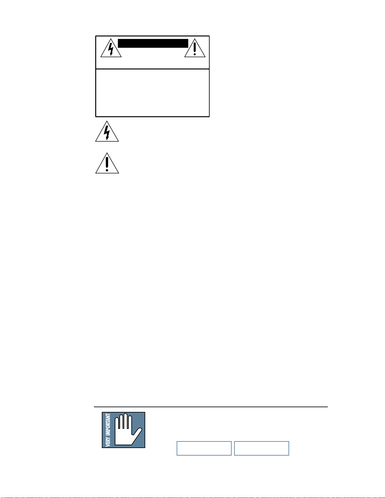
The lightning flash with arrowhead symbol within an equilateral
triangle is intended to alert the user to the presence of uninsulated
"dangerous voltage" within the product's enclosure, that may be
of sufficient magnitude to constitute a risk of electric shock to persons.
Le symbole éclair avec point de flèche à l'intérieur d'un triangle
équilatéral est utilisé pour alerter l'utilisateur de la présence à
l'intérieur du coffret de "voltage dangereux" non isolé d'ampleur
suffisante pour constituer un risque d'éléctrocution.
The exclamation point within an equilateral triangle is intended to
alert the user of the presence of important operating and maintenance
(servicing) instructions in the literature accompanying the appliance.
Le point d'exclamation à l'intérieur d'un triangle équilatéral est
employé pour alerter les utilisateurs de la présence d'instructions
importantes pour le fonctionnement et l'entretien (service) dans le
livret d'instruction accompagnant l'appareil.
9. PowerCordProtection—Powersupplycordsshouldbe
routedsothattheyarenotlikelytobewalkeduponor
pinchedbyitemsplacedupon or against them, paying
particularattentiontocordsatplugs,conveniencereceptacles,
andthepointwherethey exit this Mackie product.
10. ObjectandLiquidEntry— Care should be taken so that
objectsdonotfallintoandliquidsarenotspilledintothis
Mackie product.
11. Damage Requiring Service — This Mackie product
shouldbeservicedonlybyqualifiedservicepersonnelwhen:
A. Thepower-supplycordortheplughasbeen
damaged;or
B. Objectshavefallen,orliquidhasspilledinto
thisMackieproduct;or
C. ThisMackieproducthasbeenexposedtorain;
or
D. ThisMackieproductdoesnotappeartooperate
normallyorexhibitsamarkedchangein
performance;or
E. ThisMackieproducthas been dropped, or its
chassisdamaged.
12. Servicing — The user should not attempt to service this
Mackieproductbeyondthosemeansdescribedinthis
operatingmanual.Allotherservicingshouldbereferredtothe
MackieServiceDepartment.
13. To prevent electric shock, do not use this polarized plug
withanextensioncord,receptacle or other outlet unless the
bladescanbefullyinsertedtopreventbladeexposure.
Pourpréevenir les chocs électriques ne pas utiliser cette fiche
polariseéavecun prolongateur, un prise de courant ou une
autre sortie de courant, sauf si les lames peuvent êtreinsérées
àfondsans laisser aucune pariie àdécouvert.
14. Grounding or Polarization —Precautions should be
takensothatthegroundingorpolarizationmeansofthis
Mackieproductisnotdefeated.
15. This apparatus does not exceed the Class A/Class B
(whicheverisapplicable)limitsforradionoiseemissionsfrom
digitalapparatusassetoutintheradiointerference
regulationsoftheCanadian Department of Communications.
ATTENTION—Le présent appareil numérique n’émet pas de
bruitsradioélectriques dépassant las limites applicables aux
appareilsnumériques de class A/de class B (selon le cas)
prescritesdans le règlement sur le brouillage radioélectrique
édictéparles ministere des communications du Canada.
WARNING —Toreduce theriskof fireor
electricshock, do notexposethis appliance to
rainormoisture.
SAFETY INSTRUCTIONS
1. ReadInstructions—Allthesafetyandoperation
instructionsshouldbereadbeforethisMackieproductis
operated.
2. RetainInstructions—Thesafetyandoperating
instructionsshouldbekeptforfuturereference.
3. HeedWarnings—Allwarningsonthis Mackie productand
intheseoperatinginstructionsshouldbefollowed.
4. FollowInstructions—Alloperatingandotherinstructions
shouldbefollowed.
5. WaterandMoisture—Donotplacewater,hotorchilled
drinksontopofthisMackieProductasitmaycaseashock
hazard.ThisMackieproductshouldnotbeusednearwater–
forexample,nearabathtub,washbowl,kitchensink,laundry
tub,inawetbasement,nearaswimmingpool,swamp,or
salivatingSt.Bernarddog, etc.
6. Ventilation—ThisMackieproductshouldbesituatedso
thatitslocationorpositiondoesnotinterferewithitsproper
ventilation.Forexample,the Component should not be
situatedonabed,sofa,rug,orsimilarsurfacethatmayblock
anyventilationopenings,orplacedinabuilt-ininstallation
suchasabookcaseorcabinetthatmayimpedetheflowofair
throughventilationopenings.
7. Heat—ThisMackieproductshouldbesituatedaway
fromheatsourcessuchasradiatorsorotherdeviceswhich
produceheat.
8. PowerSources—This Mackieproductshouldbe connected
toapowersupplyonlyofthetypedescribedinthese
operationinstructionsorasmarkedonthisMackieproduct.
Monitor 1 Monitor 2
• Please write the serial number for your studio monitor here
(both studio monitors if you have two) for future reference
(i.e., insurance claims, tech support, return authorization, etc.):
Purchased at:_____________________________ Date of Purchase:_____________

3
INTRODUCTION
In short, all the complex interconnected
componentsin thesystemaredesignedto work
inharmony witheach othertoproducethebest
possiblesound.
The Transducers...
Themonitors featurean 8.75-inchdie-cast
magnesiumframe wooferanda1-inchviscous
edge-dampedaluminum-alloydometweeteron
thefront, anda6-inchx12-inchellipticalflat
pistonpassive radiatorintheback.
Thehigh-frequencydriveris mountedon a
massive,acousticallynon-resonantdie-castzinc
exponentialwaveguidewhichresultsinwide,
controlleddispersionofhigh-frequencysounds.
Theunique passiveradiatordesignprovidesa
smoothresponsedownto39Hz— anastounding
accomplishmentfor acabinetofthissize! And
sincetheradiatorisproducingmostofthesoundat
thelowestfrequencies,thereisverylittledistortion
fromthe wooferbecauseitsconemovement is
minimalatthosefrequencies.
The Cabinet...
Thecabinetismadeofhigh-densityMDFwood.
Aninternal“H”bracefurtherincreasesthestrength
andrigidity (stiffness)ofthebox.An open-cell
adiabaticfoammaterial fillstheinside ofthe
box toabsorb internalreflectionsanddampen
standingwaves.
FR Series Power Amplifiers...
Whatbetter waytopowertheloudspeakers
thanwithouracclaimedFRSeries“FastRecovery”
poweramplifiers.OurFastRecoverydesignuses
lownegative feedback,yetallowsthe amplifiers
tomaintainlow distortionand stabilityeven
whendrivenintoclipping.
Thelow-frequencyamplifierproduces upto
150watts continuous(350wattspeak)before
clipping,whilethehigh-frequencyamplifierproduces
upto 100watts continuous(210wattspeak).
Thankyou forchoosingMackieDesigns’
HR824Studio Monitors.Werealizethatmonitors
areacriticallyimportanttoolwhetheryourappli-
cationisstudiorecording,audio/video post
production,hi-fi,orhometheater.Knowingthis,
GregMackiehadasimplemandate:Design a refer-
encemonitorwith adegreeof accuracyand
versatilityunmatched byanyotherinitssizeand
pricecategory —oranysizeandprice category
forthatmatter. Themandate was simple,but
accomplishingitwas anotherstory!
Investments in Excellence...
Toaccomplishthe taskat hand,Gregand the
NewProduct Developmentteamrealized thata
commitmentwasrequiredintermsofnewresources
andnew equipment.So werecruitedsome ofthe
bestspeakerandacousticengineersin theindus-
trytoassistinthedesignoftheHR824.Andwe
investedin someadvanced (andneedwesay
expensive)measurementandanalysistoolsfor
thedesign teamto use.
Theresult?The HR824StudioMonitorsare
extremelyaccurate andversatile,loadedwith
uniquecontrols thatallowyoutofine-tune the
soundtomatch yourindividual environment
precisely. You’re gonnalove these!
What are they? The Advantages...
TheHR824StudioMonitorsarehigh-resolution,
two-way,bi-amplified,activemonitorsemploying
a6th-order Butterworthsystemwithabuilt-in
rear-firingmass-loadedpassiveradiator.Whew!
Therearemany benefitstointegratinganactive
crossover,poweramplifiers,anddriversintoa
singlecabinet,andwe’vetakenfulladvantageof
thesebenefits inthe designoftheHR824.
• Thecrossover pointis designedsothatthe
highand lowfrequencydriversarefedonly
thefrequenciestheyarebestabletoreproduce.
• Theamplifiers aredesigned toprovide
maximumacoustic outputfromthe speakers,
yetminimize thedangerofspeakerdamage
duetooverdriving.
• Inaddition, theamplifiers’gainandfre-
quencyresponsesareindividually
hand-trimmedtocompensatefortypical
manufacturingtolerancesbetweenthe
driversand produceasmoothfrequency
responsefrom39Hz to20kHz (±1.5dB).
• Theconnectingwirebetweentheamplifier
outputsand thedrivers arekept toan
absoluteminimum, sothedampingfactorof
theamplifier isn’tcompromisedby the
resistanceoflong speakercables.
• Theacoustic sumof theoutputsfromthetwo
driversareoptimizedelectronically,aswellas
physically,sotheamplituderesponseisunity
andthephasedifferenceisminimal.
TweeterWoofer
Passive Radiator
"H" Brace
Power Amplifier/
Crossover Assembly
Figure1. HR824Cutawaysideview

4
1. Connecttheline-levelmonitorsignalfrom
yourmixer(orother signalsource) tothe
SIGNAL INPUT
jackonthe HR824
StudioMonitor(
1
⁄
4
-inchTRS,XLR,orRCA).
2. ConnectthesuppliedAC powercord tothe
IECsocket on thebackofthemonitor.
PlugtheotherendintoanACoutletproperly
configuredwiththecorrectvoltageforyour
particularmodel.
3. Setthe
POWER MODE
switchon the
rearpaneltothe
ON
position. Withthe
powerswitch on thefrontpanelinthe
downposition,thepoweramplifierisin
Standbymode.
4. Startyoursignalsource(tapedeck,CD,
DAW,orwhatever),butleavethemaster
levelcontrolonyourmixerdown.
5. Setthe powerswitch onthefrontofthe
HR824to the
ON
position. Thered
PWR
LED willturnon.
6. Slowlyturnup the
INPUT SENSITIVITY
controlon thebackofthemonitortoits
fullyclockwiseposition
(NORMAL)
.
7. Adjustthemastervolume onyour mixerto
acomfortablyloudlisteninglevel.Enjoythe
silkysmoothhighsandauthoritative,
commandinglowsoftheHR824.Thenread
therestofthismanual…especiallythe
following:
QUICK START.
Werealizethatyoucan’t
waitto hookupyournew
MackieDesignsHR824
HighResolutionStudio
Monitorsandtrythemout.
Nevertheless,pleasetakethetimetoreadthis
pageNOW,andtherestcan waituntilyou’re
goodandready.
EachoftheHR824cabinetshasitsownbuilt-
inpoweramplifiers.That’sright,twoamplifiers
perspeakercabinet;oneforthehigh-frequency
tweeterandoneforthelow-frequencywoofer.
Youshouldturnthe
INPUT SENSITIVITY
controlontheback ofthe cabinetdown(fully
counterclockwise)beforeturningontheStudio
Monitorsfor thefirst time.Alsobesureto set
thepower switch onthe frontpanel toits
standbyposition(down).Thiswillpreventyou
fromaccidentallyconnectingahotsignalsource
tothemonitorsandgettingarudesurprise.
Thereareanumberofothersettingsyou
canmake onthebackoftheHR824,and you
canlookatthegraphicinstructionsrelatingto
eachof themonthebackofthecabinet (or
waituntil youreadaboutthemlateronin this
manualso youreallyknowwhattheydo).For
now,justleavethematthefactorydefaultset-
tings(
ACOUSTIC SPACE = WHOLE; LOW
FREQ = 37Hz; HIGH FREQ = 0
),exceptfor
the
POWER MODE
switch.Besureitisset
tothe
STANDBY
position.
OL
PWR
HI H RESOLUTION
STUDIO MONITOR
ON

5
ACOUSTIC SPACE HI H FREQ. POWER MODE
NORMALOFF
HALFQUARTER
A B C
WHOLE
(NORMAL)
0
(NORMAL)
–
2dB
+
2dB
INPUT
SENSITIVITY
ACOUSTIC SPACE APPLICATIONS
C
SPEAKERS A AINST WALLSPEAKERS IN CORNERS
B
CONSOLE
CONSOLE
A
HALF SPACE
QUARTER SPACE
SPEAKERS AWAY FROM WALLS
CONSOLE
WHOLE SPACE
• 0dB (START HERE) UARANTEED FLAT
USE FOR MOST APPLICATIONS
• +2dB: USE IF YOUR MIXES TRANSLATE BRI HT
•
–
2dB: USE IF YOUR MIXES TRANSLATE DULL
• USE 80Hz TO EMULATE SMALL SPEAKER
• USE 47Hz FOR NORMAL LF PERFORMANCE
• USE 37Hz FOR NORMAL EXTENDED
LOW FREQ PERFORMANCE
HI H FREQ.
0dB
–
2dB
10kHz
+2dB
–
3dB
LOW FREQ
LOW CUT
24dB/oct LOW CUT
BUTTERWORTH
47Hz 80Hz
37Hz
0
dB
ACOUSTIC SPACE
0
dB
–
2dB
–
4
dB
20
ROOM COMPENSATION
100Hz
FREE FIELD ACOUSTIC RESPONSE
1k
22 k
Hz
37Hz
–
3dB
–
3dB 1.5dB 39Hz
–
20kHz
+
–
LOW FREQ
37Hz80Hz 47Hz
LOW CUT
–
10 dB
(NORMAL )
LISTED COMMERCIAL
AUDIO EQUIPMENT
9Z39
R
MAINS INPUT
120VAC
60 Hz 150W
SI NAL INPUTS BAL /UNBAL
XLRPHONE RCA
INTERNAL BI•AMPLIFICATION
150W. L.F. / 100W. H.F.
™
SERIAL NUMBER
RISK OF ELECTRIC SHOCK
DO NOT OPEN
WARNING:
TOREDUCETHERISKOFFIREORELECTRIC SHOCK, DO NOT
EXPOSETHISEQUIPMENTTORAINORMOISTURE.DO NOT REMOVE COVER.
NOUSERSERVICEABLEPARTSINSIDE. REFER SERVICINGTOQUALIFIEDPERSONNEL.
CAUTION
AVIS:
RISCQUEDECHOCÉLECTRIQUE— NE PASOUVRIR
CONCEIVED, DESI NED, AND MANUFACTURED BY MACKIE DESI NS INC • WOODINVILLE • WA • USA
MADE IN USA • PATENTS PENDIN • © 1997 MACKIE DESI NS INC. ALL RI HTS RESERVED
"MACKIE", "FR SERIES", AND THE "RUNNIN MAN" FI URE ARE RE ISTERED TRADEMARKS OF MACKIE DESI N INC.
PATENT NO:
DES. 387,351
AUTO
STANDBY
ON
ON

6
OL
PWR
HI H RESOLUTION
STUDIO MONITOR
ON
OFF
;
OL
PWR
HI H RESOLUTION
STUDIO MONITOR
ON
OFF
;
Figure2.HorizontalPlacement
Additional Tidbits of Wisdom
• Whenyoushutdownyourequipment,turn
offtheHR824studiomonitorsfirstto
preventthumpsandothernoisesgenerated
byanyupstreamequipmentfromcoming
outthespeakers.Whenpoweringup,turn
onthemonitorslast.
• Savethe shippingbox! Youmayneedit
someday,andyoudon’twanttohavetopay
foranotherone.
• Saveyour salesreceiptin asafe place.
• AlsorecordbothHR824serialnumbersin
thespaceprovidedontheinsidefront
cover,alongwithwhereandwhenyou
boughtthem.
Placement
TheHR824s weredesignedto beplaced ina
verticalposition.Ifyoufinditnecessaryto
placethespeakersinahorizontalposition(on
theirsides),placethemsothatthewoofersare
towardthe inside;that is,so thewoofers are
closesttoeachother.This providesthebest
low-frequencysummingandoverallimaging.
AN EXTREMELY IMPORTANT NOTE
ON HR824 BASS RESPONSE AND
YOUR CONTROL ROOM.
YournewHR824sachieve
theirbestbassresponsein
aroomthat’soptimized for
bassreproduction.Alotof
factorscanconspireto
thwarttheHR824s’extendedlowfrequency—
includingroomshape,roomvolumeand
acousticaltreatment.
Thisis nota cop-outoranapology. It’splain
oldphysicsinaction.Luckilywe’vearmedyou
withsomecompensatingcontrolswhichyou
canusetooptimizethefrequencyresponseof
thespeakersinyourparticularroom.Consider
thefollowing:
The ACOUSTIC SPACE switch
must be set correctly.
Whenyouput your HR824sinacorneror
upagainstwalls,theirbasscharacteristics
change.Adjustthe
ACOUSTIC SPACE
switchsettingaccordinglytoavoidmuddyor
exaggeratedlowfrequencyresponse.
Feel free to experiment.
Inmanyrespects,everycontrol roomis
uniqueintermsofitsacoustics.
Evenafter you’vereadabout howtosetthe
HR824’srearpanelswitches,tryothersettings
toseeifyourparticularroomenvironment
requiresdifferentadjustments.
And,evenafteryou’veplacedyourmonitors
whereyouthinkthey’llsoundbest,trymoving
themaround.Youmightbepleasantlysurprised.
Finally, keep an open mind about
improving your room’s acoustics
and bass-handling ability.
Nobodylikes tobuyanewsetofmonitor
speakersandthenbetoldthattheyshould
spendextrabucksonbasstrapsoraremodeling
job.Butthesimplefactis,“standard”rooms,
i.e.rectangularroomsinconventionalbusiness
orresidentialstructures,arerarelyifever
conducivetooptimallowbassreproduction
withoutsomemodifications.
Luckily,thereareplentyof optionsshort of
buildinganewcontrolroom,manyofwhich
arecoveredinthismanual.

7
®
PartNo. 820-226-00 Rev.A 12/00
©2000 Mackie Designs Inc., All Rights Reserved.
Printed in the U.S.A.
A Few Words About THX®pm3™
Certification
Nearlytwodecadesago,GeorgeLucas
turnedapassionforgreatsound intothe
world’smostacceptedandtrustedsolutionfor
achievingit.ThestandardwasnamedTHX
(forTomlinsonHolman,whodevelopedthe
THXSoundSystemwhen hewas theresearch
andtechnicaldirectoratLucasArts
®
inthe
early80s),andtoday,withhundredsofthou-
sandsofhometheatercustomersandmore
than3000THXCertifiedmovietheatersenjoy-
ingitsbenefits,the THXname hasbecome
nothingshortoflegendary.Simplyput:whenit
comesto premiumsound,noothernameso
closelydefines‘quality’formillionsofmovie-
goersandhometheaterenthusiastsalike.
Today,anewlandscapeisemerging.Aland-
scapecomprisedofhundredsofsmall,
professionalmulti-channelfacilities,whose
needfordifferentiation,experttechnicaland
marketingsupport,andatrue,multi-channel
standardisbecomingacompetitivefactoflife.
Again,THXhasasingularsolutionandthis
timeit’scalledTHXpm3Certification.
Allfacilitiesinvolvedwithmixingand/or
monitoringofmulti-channelmaterialshould
havethe optionto usepm3.THXpm3Certifi-
cationisidealforDVDmastering,sweetening,
andmixing;andisalsoperfectforfacilitiesdo-
ingworkinbroadcast,music,ormulti-media
applications.
HR824 THX pm3 Certification
WhenwesubmittedtheHR824sforTHX
pm3Certification,theypassedonthefirsttry
withnomodifications!
AnyoneseekingTHXCertificationfortheir
studio,orstrivingtomaintainTHXstandards,
canuse theHR824s andrestassuredthat their
facilityisinfullcompliance.(Celebratingwith
ajumbo Bucket‘o Popcornwith extrabutter is
highlyrecommended!)
CONTENTS
INTRODUCTION ...........................................3
QUICK START ..............................................4
REAR PANEL DESCRIPTION ...........................8
SIGNAL INPUTS ....................................8
INPUT SENSITIVITY ...............................8
ACOUSTIC SPACE ..................................8
LOW FREQ ...........................................9
HIGH FREQ ..........................................9
POWER MODE....................................10
MAINS INPUT ....................................11
PASSIVE RADIATOR ............................11
FRONT PANEL DESCRIPTION .......................12
POWER SWITCH.................................12
PWR LED........................................... 12
OL (Overload) LED...............................12
PROTECTION CIRCUITS ...............................12
Overload Protect................................. 12
Thermal Protect ..................................13
INTEGRATED MAGNETIC SHIELDING.............13
INPUT SIGNAL WIRING ..............................13
Service Info .....................................................14
Troubleshooting ........................................14
Repair .....................................................15
Technical Information ........................................16
Block Diagram ..........................................16
Specifications............................................16
Graphs ....................................................18
Colophon .......................................................19

8
REAR PANEL DESCRIPTION
INPUT SENSITIVITY
NORMALOFF
INPUT
SENSITIVITY
–
10 dB
TheHR824expectsaline-levelsignalatits
inputconnectors.
• Thereferencesensitivityis–7.5dBu=100dB
SPLatonemeter(39inches)withthe
INPUT
SENSITIVITY
controlset toits
NORMAL
position(inotherwords,wideopen).
• TheHR824is designed tooperatewitha
+4dBusignalwhenthe
INPUT SENSITIVITY
controlis inthe
NORMAL
position.
• Refertothe
QUICK START
sectionon
page4forthelevel-setting procedure.
ACOUSTIC SPACE
Thisisathree-wayswitch thatadjusts the
low-frequencyresponseofthespeakerstocom-
pensatefortheirplacementintheroom.
ACOUSTIC SPACE
HALFQUARTER
A B C
WHOLE
(NORMAL)
• Ifyouplacethe HR824monitors againsta
wall(half space ),setthe
ACOUSTIC
SPACE
switch tothe“
B
”position. This
activatesashelvingfiltertoreducethelow-
frequencyoutput by2 dBto compensatefor
thehalf-spaceplacement.
• Ifyouplace the monitorsintothe corners
of your room(quarter space ),thelow-
frequencyoutputapproximatelydoubles
fromwhat itisinhalfspace.Setthe
ACOUSTIC SPACE
switchto the“
A
”
positionto reducethelow-frequency
outputby4 dB tocompensateforthe
quarter-spaceplacement.
• IfyouusetheHR824sfree-standing,away
fromwallsandcorners(wholespace ),
setthe
ACOUSTIC SPACE
switchto the“
C
”
position(
NORMAL
).
Thisis whereyouconnectyoursignaltothe
monitor,andmakeadjustmentstothefrequency
responseofthespeakerstomatchthemonitor’s
locationandyourroom’senvironment.
SIGNAL INPUTS
Thelocationofthesignalinputjacksmakes
theconnectorsexitdownandnotstraightout
thebackoftheenclosure.Thisflush-mountde-
signallows youto placethe monitorrightup
againstthewallifdesired.
• XLRfemale,TRSfemale,andRCAfemale
connectors,parallelconnected.
• Don’tconnect morethanone sourcetothe
jacks.
• Youcanusetheremainingjacksas“Thru”
jacksfordaisy-chainingthesignalto
anothermonitorortoanotheramplifier.If
youdothis,beawarethatunbalancingthe
signalanywherealong thechain doesso for
alldevicesconnectedtothechain.This
negatesthebenefitsassociatedwith
balancedlinesandinputs.
• UnbalancedTS(tip-sleeve)linescanbe
accommodatedviatheTRSjack.Makesure
thecable terminateswith aTSplug(likea
guitarplug), orifit’saTRSplug(suchasa
headphoneplug),makesuretheringistied
tothe sleeveandthattheplugisfully
insertedintothejack.
• Whenusing aTSorTRSplug,makesureit
ispushedallthe wayintothejack.Par-
tiallyinsertingtheplugintothejackcould
resultinadropinsignallevel(by 6dB).
• TheXLRandTRSinputconnectorsaccept
balancedorunbalancedsignals.The
connectorsarewiredasfollows(perthe
AES/IECstandard):
XLR TRS RCA
Hot(+) Pin2 Tip Tip
Cold(–) Pin3 Ring —
Shield(Ground) Pin1 Shield Shield
• TheHR824s canbeusedwithahome
receiverevenifthereceiverlacksapreamp
outputbyusingaspeaker-leveltoline-level
signalattenuator.(Seepage13formore
information.)

9
somewhat.Low-frequencyinformationrequires
thelargestamountofanamplifier’soutput,so
restrictingthelow-frequencycontentallows
raisingthemid-frequencylevelsomewhat.If
yourclientinsistsonmixingLOUD,thismaybe
aworkablestrategy.
HIGH FREQ
HIGH FREQ
0
(NORMAL)
–
2dB
+
2dB
The
HIGH FREQ
switch tailorstheoverall
high-frequencyresponseby±2 dBat10kHz.
Leavethis switchinthe
0 (NORMAL)
position
unless:
• Youwanttosubtlybrightenordarkenthe
soundofthespeakers.
• Perhapsyouhavehearinglosscausedby
toomany nightsin frontofadouble
Marshallstack.
• Youjustliketomix onthebrightsideor
dullside.
Ifyourmixesconsistentlysounddullordark
whenyoulistenelsewhere,thisusuallyindicates
thatyourmonitorsaretoobright,relativeto
yournormalhearing.Abitlesshigh-frequency
energyusuallyfixesthis,andyoucanforce the
mixinthisdirectionby reducing the high-
frequencyoutput of the monitors by using
the –2dB position of the switch.
LOW FREQ
LOW FREQ
3 Hz80Hz 4 Hz
LOW CUT
(NORMAL )
The
LOW FREQ
switch insertsasteep low-
frequencyrolloffintotheresponsecurve.
• Formanyapplications,thelow-frequency
outputoftheHR824mayimpairyourability
tomakemixjudgements.
• Formostapplications,usethe
47Hz
setting.
• Ifyouwantorneedtheextralow-frequency
capability,byallmeansusethe
37Hz
(NORMAL)
position.
• The
LOW FREQ
switch affectsthelow-
frequencycontentofyourmix.Remember
howthingsworkinreverse,so removingthe
deepbasscontentonplaybackmayactually
increaseitinthefinalmix.
• You canusethe
LOW FREQ
switch’s
80Hz
positiontosimulateasmallerloudspeaker,
especiallyonewithlimitedlow-frequency
capability(likeacertainpopular2-way
nearfieldmonitor).Youmayneedtodothis
ifasmallspeakeristheeventualdestina-
tionof yourmix,orperhapsjusttoseehow
yourmix soundson aclockradio.
Removingthe low-frequencycontentalso
allowsyoutoraisetheoveralloutputlevel
ACOUSTIC SPACE HIGH FREQ. POWER MODE
NORMALOFF
HALFQUARTER
A B C
WHOLE
(NORMAL)
0
(NORMAL)
–
2dB
+
2dB
INPUT
SENSITIVITY
FREE FIELD ACOUSTIC RESPONSE
1k
22 k
Hz
3 Hz
–
3dB
–
3dB 1.5dB 39Hz
–
20kHz
+
–
LOW FREQ
3 Hz80Hz 4 Hz
LOW CUT
–
10 dB
(NORMAL )
LISTED COMMERCIAL
AUDIO EQUIPMENT
9Z39
R
MAINS INPUT
120VAC
60 Hz 150W
SIGNAL INPUTS BAL/UNBAL
XLRPHONE RCA
INTERNAL BI•AMPLIFICATION
150W. L.F. / 100W. H.F.
™
SERIAL NUMBER
RISK OF ELECTRIC SHOCK
DO NOT OPEN
WARNING:
TOREDUCE THERISK OF FIRE ORELECTRIC SHOCK, DONOT
EXPOSETHIS EQUIPMENTTO RAIN OR MOISTURE.DO NOT REMOVECOVER.
NOUSERSERVICEABLE PARTS INSIDE. REFERSERVICING TO QUALIFIED PERSONNEL.
CAUTION
AVIS:
RISCQUEDECHOC ÉLECTRIQUE — NEPASOUVRIR
CONCEIVED, DESIGNED, AND MANUFACTURED BY MACKIE DESIGNS INC • WOODINVILLE • WA • USA
MADE IN USA • PATENTS PENDING • © 199 MACKIE DESIGNS INC. ALL RIGHTS RESERVED
"MACKIE", "FR SERIES", AND THE "RUNNING MAN" FIGURE ARE REGISTERED TRADEMARKS OF MACKIE DESIGN INC.
PATENT NO:
DES. 38 ,351
AUTO
STANDBY
ON
ON

10
Conversely,ifyourmixesareconsistently
toobright,thenaddingsomeadditionalhigh
frequencyenergyinthemonitorssatisfiesyour
ears,andtheresultantmixhaslessHFcontent.
Thetimbreofyourmonitors
affectsthewaythatyour
mixesplayonotherequip-
ment.Rememberthatthe
monitorshaveamirroring
effectonthemix;ifthe monitorsmake some-
thingtoo loudin themixitusuallyresultsin
notenough ofthat thingontape.
Startwiththeresponsemodification
switchesinthefactoryrecommendedsettings
(seeQuickStartSection ).Afterprolonged
listening,ifyounoticeatrendinyourmixes,
perhapsmakingsomesmalladjustmentsas
suggestedherewillhelp.
It’sarealrushtomixreallyloud. Butre-
memberthattheresultingmixonlysounds
goodwhen youplay itatleastthatloud.How-
everstrange itmay sound,mixes madeat
lowerlevelssoundevenbetterwhenplayed
loud;perhapsevenabitbiggerthanlife.
Getthatsoundlevelmeterout.Decidewhat
levelyou’regoing tomixatandusethemeter
tohelp keepyour mixingatthatlevel.Your
earswillthank you, andyourmixeswill be
betterfor it.
POWER MODE
POWER MODE
AUTO
STANDBY
ON
ON
This3-positionswitchturnstheamplifiers
onoroff,orsetsthemtoautomaticmode.Use
thisswitchtosettheHR824stoyour preferred
modeofoperation,andusethefrontpanel
power
switchforconvenience.
• Inthe
STANDBY
position, thepower
amplifiersareinStandbymodeand
producenosound.Low-levelcircuitryis
stillactive,butthepowerconsumptionof
thecircuitryisminimal(8watts).
• Flipthe switchtothe
ON
position andthe
poweramplifiersareliveandoperate
normally.(Thefrontpanelpower switch
mustalsobe
ON
.)
• Sincethepowersupplyandlowlevel
circuitryarealreadyactive(assumingthe
speakerispluggedinto alive outlet),this is
an“instanton”function.
• Whenit’sinthe
AUTO ON
position, the
amplifiersturnonandoffdependingonthe
presenceorabsenceofaninputsignal.An
ACOUSTIC SPACE HIGH FREQ. POWER MODE
NORMALOFF
HALFQUARTER
A B C
WHOLE
(NORMAL)
0
(NORMAL)
–
2dB
+
2dB
®
INPUT
SENSITIVITY
ACOUSTIC SPACE APPLICATIONS
C
SPEAKERS AGAINST WALLSPEAKERS IN CORNERS
B
CONSOLE
CONSOLE
A
HALF SPACE
QUARTER SPACE
HIGH RESOLUTION
STUDIO MONITOR
SPEAKERS AWAY FROM WALLS
CONSOLE
WHOLE SPACE
• 0dB (START HERE) GUARANTEED FLAT
USE FOR MOST APPLICATIONS
• +2dB: USE IF YOUR MIXES TRANSLATE BRIGHT
•
–
2dB: USE IF YOUR MIXES TRANSLATE DULL
• USE 80Hz TO EMULATE SMALL SPEAKER
• USE 4 Hz FOR NORMAL LF PERFORMANCE
• USE 3 Hz FOR NORMAL EXTENDED
LOW FREQ PERFORMANCE
HIGH FREQ.
0
dB
–
2dB
10kHz
+2dB
–
3dB
LOW FREQ
LOW CUT
24dB/oct
LOW CUT
BUTTERWORTH
4 Hz 80Hz
3 Hz
0
dB
ACOUSTIC SPACE
0
dB
–
2dB
–
4
dB
20
ROOM COMPENS ATION
100 H z
FREE FIELD ACOUSTIC RESPONSE
1k
22 k
Hz
3 Hz
–
3dB
–
3dB 1.5dB 39Hz
–
20kHz
+
–
LOW FREQ
3 Hz80Hz 4 Hz
LOW CUT
–
10 dB
(NORMAL )
LISTED COMMERCIAL
AUDIO EQUIPMENT
9Z39
R
MAINS INPUT
120VAC
60 Hz 150W
SIGNAL INPUTS BAL /UNBAL
XLRPHONE RCA
INTERNAL BI•AMPLIFICATION
150W. L.F. / 100W. H.F.
™
SERIAL NUMBER
RISK OF ELECTRIC SHOCK
DO NOT OPEN
WARNING:
TOREDUCETHE RISK OF FIREOR ELECTRIC SHOCK, DONOT
EXPOSETHISEQUIPMENT TO RAIN ORMOISTURE. DO NOT REMOVECOVER.
NOUSER SERVICEABLE PARTS INSIDE.REFER SERVICING TO QUALIFIED PERSONNEL.
CAUTION
AVIS:
RISCQUEDE CHOC ÉLECTRIQUE —NEPASOUVRIR
CONCEIVED, DESIGNED, AND MANUFACTURED BY MACKIE DESIGNS INC • WOODINVILLE • WA • USA
MADE IN USA • PATENTS PENDING • © 199 MACKIE DESIGNS INC. ALL RIGHTS RESERVED
"MACKIE", "FR SERIES", AND THE "RUNNING MAN" FIGURE ARE REGISTERED TRADEMARKS OF MACK IE DESIGN INC.
PATENT NO:
DES. 38 ,351
AUTO
STANDBY
ON
ON
OL
PWR
ON

11
TheHR824isabassreflex6th-ordersystem.
Ratherthanuseports, thevent takesthe form
ofapassiveradiator, amass-loadedflatpiston
coupledtotheairtrappedwithintheenclo-
sure.Youcan’tseethepassiveradiatorbecause
itis locatedat therearofthecabinet,behind
thepoweramplifierassembly.
• Simpleportsorductsmusthavesufficient
surfaceareato preventthe velocityof the
airwithin themfrom exceeding5% ofthe
speedofsound,which keepsthe ventfrom
becomingaudible(breathingandwheezing
sounds)athighsignallevels.
• Thisrequirementforsufficientsurfacearea
createsadesignproblemwhenusingports—
findingenoughspaceintheenclosurefor
themtofit.
Thepassiveradiatorreplacestheportfound
onmostspeakersystems.Itoffersseveralad-
vantagestosimpleporting:
• Oneprimaryadvantageisthatapassive
radiatorcanreproducelowfrequencies
withlowerdistortionandatahighersound
pressurelevel(SPL)thanasimpleportor
duct.
• Ouruniquepassiveradiatordesignusesa
diaphragmmadewithacompositehoney-
combmaterialprovidingexceptional
stiffnesstotheradiatingsurface.
• Theellipticalshapeofthepassiveradiator
takesupnearlytheentiresurfacearea
availableontherearoftheenclosure,
allowingthepassiveradiatortomovemore
airthan aport.
inputsignallevelof–45dBu(minimum)
activatestheauto-onfunction.Asilent
periodgreaterthanfiveminutesactivates
theauto-off function.Thered
PWR
LED
onthefront panelreflectsthe stateof the
amplifiers.
MAINS INPUT
ConnectthepowercordtothisIECsocket,and
plugthe otherend intoyour ACoutlet.
• Whenthe
POWER MODE
switchis in
the
ON
position, andthepower switch
isin the
ON
position, applyingACpower
activatesthemutingcircuitforaboutfour
secondswhilethepowersupplyand
internalcircuitrystabilize.
PASSIVE RADIATOR
Whenyou mounta loudspeakerin abox,
therearetwothingsthatyoucandowiththe
radiationfrom therearofthecone:useitto
enhancethelow-frequencyperformanceofthe
speakersystem(bassreflexsystem)orsoakit
up(acousticsuspensionsystem).
• Abassreflexsystemusestherearradiation
toextendthelow-frequencyresponse.Most
systemsprovideholes(ports)inthefront
orback ofthe cabinettoreleasethe rear
wave.Sometimestheholeshavetubes
(ducts)inthem.Thedimensionsofthe
holesand thevolume ofthe cabinetwork
withthecharacteristicsofthewooferto
producelow-frequencyextension.These
systemsarecharacterizedbygoodlow-
frequencyperformancedowntothe–3dB
frequencysetbythedesign. Belowthis
frequency,thefrequencyresponsefallsat
24dB/octaveormore.
Tweeter
Woofer
Passive Radiator

12
OL
PWR
ON
FRONT PANEL DESCRIPTION
Overload Protect
The high and low frequency power amplifiers
have clipping detectors that light the
OL
LED
when either power amplifier output clips.
• If you see the
OL
LED blinking more than
just occasionally, it’s an indication that you
should reduce the signal level coming from
your mixer or other signal source.
• If frequentclipping continues, the driver
thermal overload protection activates a
compressor that reduces the input level to
the amplifiers. During this time the
OL
LED lights continuously.
• The compressor was designed to protect
the speakers and its action is highly
audible.
• The compressor was not designed for
mixing!
If a client insists on listening
to the monitors at a very high
volume, you may find that
the
OL
LED lights frequently.
Since the majority of the
power requirement in any monitor are the low
frequencies, selectively reducing the low end
can provide a little more headroom and volume
for the monitors. Change the
LOW FREQ
switch to
47Hz
or
80Hz
, if necessary, to reduce
the bass response. This may allow the HR824s
to play just enough louder to satisfy the client
and to eliminate most of the amplifier clipping.
Power Switch
Use this switch to turn on or off the HR824
from the front. It works with the
POWER
MODE
switch on the rear panel in the
following way:
• If the
POWER MODE
switch on the rear
panel is set to
STANDBY
, the front panel
power
switch has no effect. The
PWR
LED remains off.
• If the
POWER MODE
switch is
ON
, the
front panel power switch turns the HR824
on or returns it to
STANDBY
mode, as
indicated by the
PWR
LED.
• If the
POWER MODE
switch is in the
AUTO ON
position, the front panel power
switch turns the HR824 on as long as there
is a signal present.
OL (Overload) LED
This LED blinks when the amplifiers begin
to clip and lights steadily if the overload protec-
tion circuit has been triggered.
• Occasional blinking of the
OL
LED indi-
cates that the loudest transients are
reaching the maximum output capability of
the amplifiers. This is okay.
• Frequent or continuous blinking of the
OL
LED indicates that you have exceeded the
maximum output capability of the amplifi-
ers and that the amplifiers are clipping. If
you persist, the overload protection circuit
takes over, reducing the input level. You
should reduce the level from your signal
source until the
OL
LED blinks occasionally
or not at all.
PROTECTION CIRCUITS
There are a number of protection mecha-
nisms designed into the HR824 to safeguard
the loudspeakers from inadvertent damage.
CAUTION:The protection circuits are de-
signed to prevent damage to the loudspeakers
under reasonable and sensible conditions.
Should you choose to ignore the warning signs
(i.e., frequent Overload LED indications, ex-
cessive distortion), you can still damage the
speakers in the HR824 by overdriving them
past the point of amplifier clipping. Such dam-
age is beyond the scope of the Warranty.

13
Thermal Protect
All amplifiers produce heat. The HR824 is
designed to be efficient both electrically and ther-
mally.
• If for some reason the heatsinks get too hot,
a thermal switch activates, placing the
HR824 into Standby mode (indicated when
the red
PWR
LED turns off).
• Should this happen, make sure that airflow
to the rear of the cabinet is not restricted.
• When the heatsinks cool down to a safe
temperature, the switch resets and normal
operation resumes.
INTEGRATED MAGNETIC SHIELDING
The HR824 Studio Monitor contains drivers
with large magnet structures. The drivers’ mag-
nets are shielded to help prevent the magnetic
field from radiating out into the environment
and playing havoc with computer monitors or
TV screens. Unshielded speakers can cause
distortion in both the shape and color of the
picture if placed too close to a CRT (cathode
ray tube). If you have a particularly sensitive
computer monitor or TV screen, it may be nec-
essary to move the speakers a few inches away.
INPUT SIGNAL WIRING
You should use high-quality, shielded cable
to connect the signal source to the
SIGNAL
INPUT
jack on the HR824.
• Foil shielded cables, such as Belden 8451,
8761, or 9501 are commonly used for studio
wiring.
• Microphone cables work well.
• The better the shield, the better the
immunity from externally induced noise
(like EMI and RFI). Route the cable away
from AC power cords and outlets. These are
common sources for hum in an audio
signal. Wall warts and line lumps are
especially insidious hum inducers!
You can purchase quality cables from your
Mackie dealer.
• In certain home theater applications, it
may be necessary to connect the speaker
outputs from a stereo receiver to the inputs
of the HR824s, if the receiver doesn’t have
preamp outputs or other line-level output
connections.
You can either make or purchase a speaker-
level to line-level attenuator to reduce the
signal from the receiver’s speaker output so
it can be connected to the HR824’s input.
The following illustrations show how to
make an attenuating pad for the balanced
XLR and TRS connectors. Use a 330 ohm
resistor (R2) for a 30 dB pad, and a 620
ohm resistor (R2) for a 25 dB pad. This
attenuator can be used safely with amplifi-
ers rated up to 500 watts into 8 ohms.
21
3
3-Conductor Cable Male
XLR
Shield
+
From Speaker Output
of Receiver
R1
(10K
.5W)
–
R2
(330Ω.25W for –30 dB)
or
(620Ω .25W for –25 dB)
2
31
SHIELD
COLD
HOT
From Speaker Output
of Receiver
R1
(10K
.5W)
R2
(330Ω.25W for –30 dB)
or
(620Ω.25W for –25 dB)
3-Conductor Cable
3-Conductor Cable
3-Conductor Cable
1/4"
TRS Plug
1/4"
TRS Plug
SHIELD
+
From Speaker Output
of Receiver
From Speaker Output
of Receiver
R1
(10K
.5W)
–
SLEEVE (SHIELD)
TIP (HOT)
RING (COLD)
TIPSLEEVE RING
TIP
R1
(10K
.5W)
R2
(330Ω.25W for –30 dB)
or
(620Ω.25W for –25 dB)
R2
(330Ω.25W for –30 dB)
or
(620Ω .25W for –25 dB)
SLEEVERING
Figure3. Speaker-levelto Line-levelXLR Pad Figure4. Speaker-levelto Line-levelTRS Pad

14
• If it’s a stereo pair, try switching them
around. For example, if a left output is
presumed dead, switch the left and right
cords at the monitor end. If the problem
switches sides, it’s not the monitor. It could
be a bad cable, or no signal from the mixer.
Bad Sound
• Is the input connector plugged completely
into the jack? If using a
1
⁄
4
” TS or TRS plug,
make sure it is plugged all the way in.
• Is it loud and distorted? Reduce the signal
level at the mixer.
• If possible, listen to the signal source with
headphones plugged into the preamp stage.
If it sounds bad there, it’s not the monitor.
• Too much bass or not enough bass? Move
around the room and see if the bass
response changes. It’s possible your
listening position coincides with a room
mode where the low frequencies either
become exaggerated or nulled. If so, try
moving the monitors to a different position,
or moving your listening position.
Noise/Hum
• Check the signal cable between the mixer
and the monitor. Make sure all connections
are secure. These problems usually produce
crackling noises or hum.
• If connecting an unbalanced output to the
HR824 balanced input, make sure the shield
is connected to the unbalanced ground and
to pin 1 of the XLR (or the sleeve of the
TRS jack).
• If a CATV cable is connected to the system,
try disconnecting it. If the hum goes away,
call your cable carrier to check for proper
grounding of the cable.
Service Info
Details concerning Warranty Service are
spelled out on the Warranty Card included with
your monitor (if it’s missing, let us know and
we’ll rush one to you).
If you think your monitor has a problem,
please do everything you can to confirm it before
calling for service, including reading through
the following Troubleshooting section. Doing
so might save you from deprivation of your
monitor and the associated suffering.
Of all Mackie products returned for service
(which is hardly any at all), roughly 50% are
coded “CND” — Could Not Duplicate, which
usually means the problem lay somewhere else
in the system. These may sound obvious to you,
but here are some things you can check:
Troubleshooting
No Power
• Our favorite question: Is it plugged in?
• Make sure the power cord is securely
seated in the IEC socket and plugged
all the way into the AC outlet.
• Make sure the AC outlet is live (check with
a tester or lamp).
• Are the power switch on the front panel
andthe POWER MODE switch on the
rear panel in the ON position?
• Is the PWR LED on the front panel
illuminated? If not, make sure the AC
outlet is live. If so, refer to “No Sound”
below.
• If the PWR LED is not illuminated, and you
are certain that the AC outlet is live, it will
be necessary to have the HR824 serviced.
Therearenouser-serviceablepartsinside.
Refer to “Repair” at the end of this section
to find out how to proceed.
No Sound
• Is the PWR LED on the front panel
illuminated? If not, refer to “No Power”
above.
• Is the INPUT SENSITIVITY control
turned up?
• Is the signal source turned up? Make sure the
signal level from the mixing console (or what-
ever device immediately precedes the studio
monitor) is high enough to produce sound.

15
1. Review the preceding troubleshooting
suggestions. Please.
2. Call Tech Support at 1-800-258-6883, 7 am
to 5 pm PST, to explain the problem and
request an RA (Return Authorization)
number. Have your monitor’s serial
number(s) ready. You must have an RA
number before you can obtain service at the
factory.
3. Set aside the power cord, owner’s manual,
or anything else that you’ll ever want to see
again. We are responsible for the return of
the monitor only.
4. Pack the monitor in its original packing
box. This is veryimportant. When you call
for the RA number, please let Tech Support
know if you need new packaging. Mackie is
not responsible for any damage that occurs
due to non-factory packaging.
5. Include a legible note stating your name,
shipping address (no P.O. boxes), daytime
phone number, RA number, and a detailed
description of the problem, including how
we can duplicate it.
6. Write the RA number in BIG PRINTon top
of the box.
7. Ship the monitor to us. We recommend
United Parcel Service (UPS). We suggest
insurance for all forms of cartage. Ship to
this address:
Mackie Designs
SERVICEDEPARTMENT
16140 Wood-Red Rd. NE, Ste. 5
Woodinville, WA 98072
8. We’ll try to fix the monitor within three
business days. Ask Tech Support for current
turnaround times when you call for your RA
number. We normally send everything back
prepaid using UPS ORANGE (Third Day
Air). However, if you rush your monitor to
us by Air Shipment, we’ll treat it in kind by
letting it jump to the head of the line, and
we’ll also ship it back to you UPS RED
(Next Day Air). This paragraph does not
necessarily apply to non-warranty service.
• Make sure the signal cable is not routed
near AC cables, power transformers, or
other EMI sources (including wall warts
and line lumps!). These sources usually
produce hum.
• Is there a light dimmer or other triac-based
(SCR) device on the same AC circuit as the
monitor? Dimmers cause buzzing noises.
Use an AC line filter or plug the monitor
into a different AC circuit.
• Excessive hiss is an indication of an
incorrect gain setting somewhere before
the speaker.
• If possible, listen to the signal source with
headphones plugged into the console. If it
sounds noisy there, it’s not the monitor.
I hear sound from the monitors after I
switch the AC power off!
• Use the front panel switch to turn the
monitors on and off, or turn off the signal
going to the monitors when the AC power is
turned off.
If you unplug the HR824 or turn off the
power strip that it’s plugged into with a signal
applied to the input, you may hear sound from
the monitor for a short period of time as the
muting circuit unmutes and the power supply
finishes discharging. This is normal and not
harmful to the monitor.
Repair
Service for the U.S. versions of our monitors
is available only from our factory, located in
sunny Woodinville, Washington. (Service for
monitors living outside the United States can
be obtained through local dealers or distribu-
tors.) If your monitor needs service, follow
these instructions:

16
+2 dB
0
2
3
1
–2 dB
HIGH FREQ.
CLIP SENSE
OVERLOAD
LED
CLIP SENSE
CIRCUIT
HF TRANSDUCER
THERMAL MODELER
BALANCED
LINE
INPUTS
UNBALANCED
LINE
INPUT
SENSITIVITY
COMPRESSOR
CROSSOVER HI-FREQ
WHOLE
HALF
QUARTER
ACOUSTIC
SPACE
LO-FREQ
SENSITIVE
CALLOUS
HF OUT
LF TRANSDUCER
THERMAL MODELER
LF OUT
TO CLIP
SENSE
HI-FREQUENCY
POWER AMPLIFIER
HI-FREQUENCY
DRIVER
LO-FREQUENCY
DRIVER
TWEET
HF OUT
LF OUT
MUTE
37Hz (NORMAL)
80Hz
LOW FREQ
47Hz
TO CLIP
SENSE
LO-FREQUENCY
POWER AMPLIFIER
MUTE
SENSE
RESISTOR
BASS CONTROL SERVO LOOP
MOTION DETECTOR
WOOF
+
–
MIDVDC
+
–LOVDC
+
–HIVDC
TOROIDAL POWER
TRANSFORMER
FUSE
Vref ON
AUTO
STANDBY
+15VDC
SIGNAL
SENSE
MUTE
ON/OFF
CONTROL MUTE
THERMAL
SWITCH
LOW AC
VOLTS SENSE
POWER SWITCH
(FRONT PANEL)
POWER
MODE
SWITCH
PWR
LED
HIGH = MUTE OFF
LOW = MUTE ON
MACKIE DESIGNS
HR824 THX
BLOCK DIAGRAM
(#110200DF)
OUTER SPACE
Technical Information
HR824 Block Diagram
Specifications
Enclosure
MaterialsandConstruction:
3
⁄
4
-inch (19mm) thick MDF construction with 1-inch
(25.4mm) thick MDF front panel with radiused edges to
minimize diffraction.
Proprietary die-cast zinc exponential wave guide for
controlled, wide dispersion from high-frequency driver.
Internal “H” brace adds to cabinet stiffness.
Open cell adiabatic “foam fill” acoustical damping mate-
rial absorbs internal reflections, preventing delayed
sound coloration.
Flush-mount connector system allows monitor to be
placed against a wall without need for connector clearance.
Transducers
Low-frequencydriver:
8.75-inch (222mm) die-cast magnesium frame, mineral-
filled polypropylene cone, oversized magnet structure,
and over 16mm cone excursion.
High-frequencydriver:
1-inch (25.4mm) viscous edge-damped aluminum-alloy
dome with ferrofluid-cooled voice coil.
PassiveRadiator:
6-inch x 12-inch (152mm x 305mm) mass-loaded
elliptical flat piston composed of aluminum honeycomb
composite with variable thickness filleted edge rubber
surround.

17
Crossover Section
CrossoverType:
Modified Linkwitz-Riley, 24 dB/octave @ 1800Hz
InputImpedance:
20kΩ, balanced bridging
Compressor:
Independent high and low frequency overload detection
AcousticSpaceEqualization:
A position: –4 dB @ 500Hz, shelving
B position: –2 dB @ 500Hz, shelving
C position: flat
LowFreqFilter:
–3 dB @ 37Hz, 2nd-order Transitional High Pass filter;
–3 dB @ 47Hz, 4th-order Chebyshev High Pass filter
(
1
⁄
10
dB passband ripple);
–3 dB @ 80Hz, 4th-order Butterworth High Pass filter
HighFreqEqualization:
±2 dB @ 10kHz, shelving
Amplifier Section
Low-frequency amplifier:
Ratedpoweroutput:
150 watts, 4Ωload
Burstpoweroutput:
350 watts
Distortion:
THD:
< 0.035%
SMPTE IMD:
< 0.035%
DIM 100:
< 0.035%
SlewRate:
> 35V/µs
Signal-to-NoiseRatio:
> 102 dB, referenced to 150 watts into 4 ohms
High-frequency amplifier:
Ratedpoweroutput:
100 watts, 6Ωload
Burstpoweroutput:
210 watts
Distortion:
THD:
< 0.035%
SMPTE IMD:
< 0.035%
DIM 100:
< 0.035%
SlewRate:
> 35V/µs
Signal-to-NoiseRatio:
> 102 dB, referenced to 100 watts into 6 ohms
Acoustic Section:
Free-FieldFrequencyResponse:
±1.5 dB, 39Hz to 20kHz
Lowercutofffrequency: –3 dB @ 37Hz
Uppercutofffrequency: –3 dB @ 22kHz
SoundPressure Levelat 1meter,
–7.5dBuintobalancedinput: 100 dB SPL @ 1m
Maximumpeak SPLper pair: ≥120 dB SPL @ 1m
Maximumshort termSPL onaxis,
halfspace 80Hzto 2.5kHz: ≥111 dB SPL @ 1m
Residualnoise(maximum gain, 600Ωsource,
20Hz-20kHz bandwidth): < 8 dB SPL @ 1m
General:
PowerConsumption:
135 watts with musical program, loud mix
18 watts quiescent (idle)
8 watts in Standby mode
ACDropoutVoltage:
120V AC versions: 80V AC
240V AC versions:160V AC
Weight: 32 lbs. 9 oz. (14.77 kg)
Dimensions(HxWxD):
15.75" (400mm) x 10.00" (254mm) x 12.20" (310mm)
Mackie Designs is always striving to improve our products
by incorporating new and improved materials, components
and manufacturing methods. Therefore, we reserve the right
to change these specifications at any time without notice.
10.00" 254.0mm
10.50" 266.7mm
12.20" 309.9mm
15.75"
400.0mm
HR824
WEIGHT
32.6 lbs.
(14.8 kg)

18
HR824 Acoustic Space Filter Response
-15
+5
-14
-13
-12
-11
-10
-9
-8
-7
-6
-5
-4
-3
-2
-1
-0
+1
+2
+3
+4
d
B
u
10 20k20 50 100 200 500 1k 2k 5k 10k
Hz
®
HR824 High Frequency EQ Filter Response
-15
+5
-14
-13
-12
-11
-10
-9
-8
-7
-6
-5
-4
-3
-2
-1
-0
+1
+2
+3
+4
d
B
u
10 20k20 50 100 200 500 1k 2k 5k 10k
Hz
®
HR824 Low Frequency Filter Response
-45
+5
-43
-41
-39
-37
-35
-33
-31
-29
-27
-25
-23
-21
-19
-17
-15
-13
-11
-9
-7
-5
-3
-1
+1
+3
d
B
u
10 20020 30 40 50 60 70 80 90 100
Hz
®
Graphs

19
This page originally contained an additional
appendix which clearly and succinctly set forth
the five simple steps to attaining perfection in
every part of your life, especially miking drums
and editing WIN.INI files…along with several
surefire methods for becoming incredibly rich
overnight. However, somewhere along the pro-
duction process, this material was lost forever.
We apologize for any potential inconvenience
this may have caused.
COLOPHON
The text is a compilation based on input
from a number of sources, including distinguished
design engineers Mats Jarlstrom and Cal
Perkins, acoustic engineers David Bie and
Terry Wetherbee, Mackie’s celebrated cerebral
technical support staff, and several species of
small furry animals gathered together in a cave
grooving with a pict. Extensive input was pro-
vided from various and sundry interested parties
including mega-SR and recording guru Rick
Chinn, our colorfully convoluted communications
connoisseur and Master Geek Ron Koliha,
Linn Compton (proofreader extraordinaire),
Sara Delahan (Art Department Diva), and Paul
Larson (Technical Support Supreme). Finally,
Dave Franzwa patiently patched the pieces
into perpetual prose with passionate precision.
Initially written in Microsoft
®
Word 6.0.1,
the text was imported into Adobe PageMaker
®
6.0 (which was upgraded to 6.5 during the pro-
duction process). Illustrations were produced
in Adobe Illustrator
®
6.0. Most of the work was
done on a Power Macintosh
®
8100/100
AV
with
Mac OS 7.6.1 installed and an external hamster-
driven power-supply which consumed 6.7 pounds
of hamster food during the production of this
manual. This machine has a PowerPC 601
processor, 136MB of RAM, a 1GB internal hard
drive, an internal Matshita CD-ROM drive, 2GB
external hard drive, and an external Iomega
Zip™ Drive for backup and transfer of files.
This entire manual was written and produced
while sitting in a comfy chair.
The following are trademarks or registered
trademarks of Mackie Designs Inc.: The Mackie
logo, HR Series, and the Running Man.
This manual also contains names and
marks of other companies which belong to
those respective companies, and are hereby
acknowledged.
HR824 design protected under the following
patent: DES. 387,351
©2000 Mackie Designs Inc.
All Rights Reserved.
Printed in the USA.
®

Some of the
people at our
Woodinville,
Washington factory
who helped
design, build, sell,
and support your
product.
Some of the
people at our
Woodinville,
Washington factory
who helped
design, build, sell,
and support your
product.
®
®
®
™
Mackie Designs Inc.
Mackie Designs Inc.
16220 Wood-Red Rd. NE • Woodinville, WA 98072 • USA
800/898-3211 • Outside the US: 425/487-4333
Fax: 425/487-4337 • www.mackie.com
E-mail: [email protected]
Other manuals for HR824
3
Table of contents
Other Mackie Speakers manuals

Mackie
Mackie S215 User manual

Mackie
Mackie HR824 User manual

Mackie
Mackie REACH Manual

Mackie
Mackie SRM210 V-Class User manual

Mackie
Mackie HD1531 User manual

Mackie
Mackie C300 User manual

Mackie
Mackie HDA User manual

Mackie
Mackie SR1530 User manual

Mackie
Mackie S225 User manual

Mackie
Mackie HD1531 User manual

Mackie
Mackie MR5mk3 User manual

Mackie
Mackie SRM350 User manual

Mackie
Mackie SRM550 User manual

Mackie
Mackie SRT21D User manual

Mackie
Mackie TH-15A User manual

Mackie
Mackie DLM8 User manual

Mackie
Mackie CR-X Series User manual

Mackie
Mackie Hotwire EX12 User manual

Mackie
Mackie TAPCO S-5 User manual

Mackie
Mackie Thump12 User manual