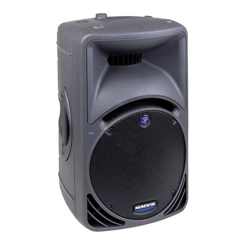
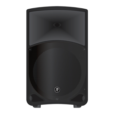
Mackie Thump12 User manual

ESD Warning:
To avoid damage by electrostatic discharge all standard ESD precautions must be taken.
Safety Warning:
Caution! These instructions are for use by qualied personnel only!
To avoid electric shock, do not perform any servicing unless you are qualied to do so.
Refer all service to qualied personnel.
CAUTION AVIS
RISK OF ELECTRIC SHOCK. DO NOT OPEN
RISQUE DE CHOC ELECTRIQUE. NE PAS OUVRIR
CAUTION: TO REDUCE THE RISK OF ELECTRIC SHOCK DO NOT REMOVE COVER (OR BACK)
NO USER-SERVICEABLE PARTS INSIDE. REFER SERVICING TO QUALIFIED PERSONNEL
ATTENTION: POUR EVITER LES RISQUES DE CHOC ELECTRIQUE, NE PAS ENLEVER LE COUVERCLE.
AUCUN ENTRETIEN DE PIECES INTERIEURES PAR L'USAGER.
CONFIER L'ENTRETIEN AU PERSONNEL QUALIFIE.
AVIS: POUR EVITER LES RISQUES D'INCENDIE OU D'ELECTROCUTION, N'EXPOSEZ PAS CET ARTICLE
A LA PLUIE OU A L'HUMIDITE
The lightning flash with arrowhead symbol within an equilateral triangle is
intended to alert the user to the presence of uninsulated "dangerous
voltage" within the product's enclosure, that may be of sufficient magnitude
to constitute a risk of electric shock to persons.
Le symbole éclair avec point de flèche à l'intérieur d'un triangle équilatéral
est utilisé pour alerter l'utilisateur de la présence à l'intérieur du coffret de
"voltage dangereux" non isolé d'ampleur suffisante pour constituer un risque
d'éléctrocution.
The exclamation point within an equilateral triangle is intended to alert the
user of the presence of important operating and maintenance (servicing)
instructions in the literature accompanying the appliance.
Le point d'exclamation à l'intérieur d'un triangle équilatéral est employé
pour alerter les utilisateurs de la présence d'instructions importantes pour le
fonctionnement et l'entretien (service) dans le livret d'instruction
accompagnant l'appareil.
Page 2 of 30
THUMP 12 SERVICE MANUAL
Page 2 of 30Page 2 of 30

Page 3 of 30
THUMP 12 SERVICE MANUAL
Page 3 of 30Page 3 of 30
Table of Contents
Specications ...............................................................................................................................4
Service Bulletins /Service Kits / Modications / Software Driver Information.........................6
Block Diagram ..............................................................................................................................7
Quick Parts ....................................................................................................................................8
Final Assembly Diagrams.............................................................................................................9
Final Assembly Quick Parts........................................................................................................12
Amp Subassembly Diagrams....................................................................................................13
Amp Subassembly Quick Parts.................................................................................................15
MG300 +75 PWR ASP Drive Subassembly Diagrams ..............................................................16
MG300 +75 PWR ASP Drive Subassembly Quick Parts ...........................................................18
2042206-XX PCB ASSY ASP TH12Av2/TH15Av2 (TOP) ..............................................................19
2042206-XX PCB ASSY ASP TH12Av2/TH15Av2 (BOTTOM) .....................................................20
2042206-XX SCHEMATIC ASP TH12Av2/TH15Av2 (INPUT).......................................................21
2042206-XX SCHEMATIC ASP TH12Av2/TH15Av2 (LF_HP_PROCESSING) ..............................22
2042206-XX SCHEMATIC ASP TH12Av2/TH15Av2 (LF & HF CROSSOVERS) ........................... 23
2042204-XX PCB ASSY POWER SUPPLY/AMP MG300+75W (Top) ..........................................24
2042204-XX PCB ASSY POWER SUPPLY/AMP MG300+75W (Bottom) ....................................25
2042204-XX SCHEMATIC POWER SUPPLY/AMP MG300+75W (Power Supply) .....................26
2042204-XX SCHEMATIC POWER SUPPLY/AMP MG300+75W(Ampliers) ............................. 27
2043052-00 PCB ASSY LED (Top) ...............................................................................................31
2043052-00 PCB ASSY LED (Bottom) .........................................................................................32
2043079-XX SCHEMATIC PCB ASSY TH-15A ..............................................................................33

Page 4 of 30
THUMP 12 SERVICE MANUAL
Page 4 of 30
Specications
THUMP12 SPECIFICATIONS
Acoustic Performance
Frequency Response (–3 dB) 57 Hz – 20 kHz
Frequency Response (–10 dB) 50 Hz – 23 kHz
Horizontal Coverage Angle 90˚
Vertical Coverage Angle 60˚
Maximum SPL Peak 125 dB SPL @ 1m
High-Frequency Section
Compression Driver 1.4 in / 36 mm
Diaphragm Material Titanium
Magnet Material Ferrite
Low-Frequency Section
Woofer Diameter 12.0 in / 305 mm [Thump12]
Cone Material Paper
Magnet Material Ferrite
Power Ampliers
System Power Amplication
Rated Power 500 watts rms
1000 watts peak
Low Frequency Power Amplier
Rated Power 400 watts rms
800 watts peak
Design Class D
High Frequency Power Amplier
Rated Power 100 watts rms
200 watts peak
Design Class AB

Page 5 of 30
THUMP 12 SERVICE MANUAL
Page 5 of 30
Specications Continued...
Input / Output
Input Type Female XLR / 1/4" Balanced
Input Impedance 20 k balanced bridging;
10 k unbalanced
Thru Male XLR balanced
Level Control Rotating Knob
0 dB at center
Sensitivity +4 dBu for full output
(Level Control @ Center)
–36 dBu for full output
(Level Control @ Max)
Electronic Crossover
Crossover Type 24 dB/octave
Crossover Frequency 3 kHz
Equalization
Low Frequency EQ ±6 dB @ 80 Hz, shelving
Mid Frequency EQ ±6 dB sweepable from
100 Hz to 8 kHz
High Frequency EQ ±6 dB @ 12 kHz, shelving
Power
US detachable line cord 100 – 120 VAC, 50 – 60 Hz, 130W
EU detachable line cord 220 – 240 VAC, 50 – 60 Hz, 130W
AC Connector 3-pin IEC 250 VAC, 10 A male
Power Supply Type Switchmode
Operating Temperature 0 - 40 ˚C
[extended ambient temperature] 32 - 104 ˚F
Safety Features
Input Protection Peak and RMS limiting,
power supply and
amplier thermal protection
Display LEDs Front / rear power ON,
Rear OL (Overload)
Construction Features
Basic Design: Trapezoidal
Material: Polypropylene
Finish: Textured
Handles: One on each side, one on top
Grille: Perforated metal with
weather-resistant coat-
ing
Display LEDs
Front: Power ON
Rear: Power ON, OL (overload)
Operating Temperature: 0 – 40 ˚C
32 – 104 ˚F
Physical Properties
Thump12:
Height: 23.5 in / 596 mm
Width: 14.5 in / 367 mm
Depth: 12.4 in / 314 mm
Weight: 29.0 lb / 13.2 kg
Mounting Methods:
Pole-mountable via the built-in socket on the bottom of the
cabinet. Be sure the pole is capable of supporting the weight
of the Thump loudspeaker.
Options
Thump12 Bag P/N 2036809-07
SPM200 Loudspeaker Pole Mount P/N 2035170-01
Disclaimer
Since we are always striving to make our products
better by incorporating new and improved
materials,
components, and manufacturing methods, we
reserve the right to change these specications at
any time without notice.
The “Running Man” gure is a registered trademark
of LOUD Technologies Inc.
All other brand names mentioned are trademarks
or registered trademarks of their respective
holders, and are hereby acknowledged.
©2014 LOUD Technologies Inc.
All Rights Reserved.
Page 6 of 30
THUMP 12 SERVICE MANUAL
Page 6 of 30
NOTES:
!!!Service Bulletins / Service Kits / Modications / Software Driver Information
(Please Review Before Servicing)!!!
Service Bulletins
None as of this document revision.
Service Kits
None as of this document revision.
Modications
None as of this document revision.
Software Driver Information
This product does not require a driver.

HF
LF
Amp
Amp
OL LED
Limiter
Limiter
Mute
Mute
Level
Control
Loudspeaker
Processing
Loudspeaker
Processing
3-Band Contour EQ
80 100-8K 12K
LO MID HI
Thermal
Monitoring
Input
XLR
Loop
Out
XLR
Block Diagram
Page 7 of 30
THUMP 12 SERVICE MANUAL
Page 7 of 30

Quick Parts
Page 8 of 30
THUMP 12 SERVICE MANUAL
Page 8 of 30
Part Number Description
2042350-00 Assy Amplier Thump12 100-120V
2042350-01 Assy Amplier Thump12 220-240V
2042206-00 ASP PCB
2042348-00 Assy Mg300 +75W Pwr Asp-Drive 100-120V
2042348-01 Assy Mg300 +75W Pwr Asp-Drive 220-240V
2039282 Power Switch Assembly
2038493 IEC Socket Assembly
2039987 HF Driver
2042755 LF Driver- 12”
2040618-03 Blue Knob
2040618-05 White Knob
2040619-01 Large White Knob
0012784-01 Side Handle
0030398 Top Handle
0030393 Cabinet Front TH12A
0030394 Cabinet Back TH12A
0007251 Top Hat/Pole Mount
43900140 Gasket Cab SRM
0030396-01 Grille
0018463-02 LED PCB
33890190 Foot
0025953 Running Man Logo
*Pricing and availability
are subject to change
without notice.
www.mackie.com For Ordering Information
Contact:
Phone: 1-800-898-3211 ext. 1623
Email: [email protected]

Page 9 of 30
THUMP 12 SERVICE MANUAL
Page 9 of 30
Final Assembly Diagrams

Page 10 of 30
THUMP 12 SERVICE MANUAL
Page 10 of 30
Final Assembly Diagrams

Page 11 of 30
THUMP 12 SERVICE MANUAL
Page 11 of 30
Final Assembly Diagrams

Page 12 of 30
THUMP 12 SERVICE MANUAL
Page 12 of 30
Final Assembly Quick Parts
Item Part Number Description
1 0030393 CABINET FRONT TH12A
2 0030394 CABINET BACK TH12A
3 2042350-00 ASSY AMPLIFIER THUMP12 100-120V
3 2042350-01 ASSY AMPLIFIER THUMP12 220-240V
4 0030398 HANDLE TOP TH12A
5 0012784-01 SIDE HANDLE - 15 MCK ACTIVE SPEAKER BLK
6 0030396-01 GRL TH-12Av2 BLACK
7 2042755 XDCR WOOFER DRIVER CONE 12 INCH
8 2043595 XDCR Compression Driver 1 inch VC with ferro-uid
10 0007251 TOP HAT/POLE MOUNT/SRM350
11 0018477-18 SCR M5 X 0.8 X 18MM PAN MCH SEMS ITLW PH STL CLRZC
12 33890190 CABINET FEET/SR1530
13 2042968 ASSY CBL SPEAKER AND FRONT LED TOP BOX
14 0018463-02 PCBA LED TH-12v2 TH-15v2
15 43900140 GASKET CAB SRM
16 0025953 LBL LOGO STAMPED METAL RUNNING MAN
17 2035521 SOUND ABSORBER INTERNAL TH-12A
18 0007247 SCR MACH M5X14 FLH PHH STL BLK
19 51992008 SCR SELFTAP PLASTIC DBL THD 4X20 PNH PHH STL BLK
20 0014654 NUT/HEX/M4 ZNC[DIN934]
21 33921580 SPCR 6.5ID 9OD 6.3THK STL ZN
22 51190336 SCR MACH M6X35 SKT HEX STL BLK
24 51240211 SCR SELFTAP 2.9X9.5 FILH PHH STL BLK
25 0010014 WASHER/FLAT/M5/DIN125A/ZINC
26 52100121 WSHR FLT M6 12OD 1.4THK STL BLK
27 0019649 SCREW/M4.8 X 1.59 x 45MM PH RWASHER/DUAL THREAD/
TFS/BLK
28 019650 SCREW/M4.8 X 1.59 x 20MM PH RWASHER/DUAL THREAD/
TFS/BLK
29 1160335 SCR M4 X 16 PH FHMS BLK ZINC[DIN965A]
30 0032856 LBL SERIAL NUMBER GENERIC 35mm X 9.5mm UL
31 0033468 LBL REVISION GENERIC 13mm X 9.5mm
32 2043622 SPACER PANEL AMP THUMP
33 2034504 SILICONE RTV NON-FLOWABLE PASTE

Page 13 of 30
THUMP 12 SERVICE MANUAL
Page 13 of 30
Amp Subassembly Diagrams

Page 14 of 30
THUMP 12 SERVICE MANUAL
Page 14 of 30
Amp Subassembly Diagrams

Page 15 of 30
THUMP 12 SERVICE MANUAL
Page 15 of 30
Amp Subassembly Quick Parts
Item Part Number Description
1 2042349-00 PANEL AMPLIFIER THUMP12 100-120V
1 2042349-01 PANEL AMPLIFIER THUMP12 220-240V
2 2042206-00 PCB ASSY ASP TH-12Av2
3 2042348-00 ASSY MG300 +75W PWR ASP-DRIVE 100-120V
3 2042348-01 ASSY MG300 +75W PWR ASP-DRIVE 220-240V
4 2039282 ASSY CBL SWITCH POWER NANO
5 2038493 ASSY CBL IEC INT W 50MM 16AWG GND WIRE
6 2040618-03 KNOB ANALOG UNIVERSAL BLUE
7 2040618-05 KNOB ANALOG UNIVERSAL WHITE 100
8 2040619-01 KNOB ANALOG LARGE UNIVERSAL WHITE 100
9 700-055-00 SCR MCH 4-24X3/8 PHP BLK HILO
10 2042613 SCR MACH M3X8 PNH PHILLIP STL BLK NI
11 0000659 NUT HEX KEP M3
12 0013712-010 CBL ASSY 12 PIN 2.5MM TJC3 SINGLE ROW 10 CM LEN
13 0010597 NUT HEX KEP M4
14 2043373 SHIELD AMP MG300 +75W
15 730-001-00 THERMAL COMPOUND
16 0007794-06 SCR M3 X 6MM PAN MCH EXT SEMS PH STL CL ZINC
17 014654 NUT/HEX/M4 ZNC[DIN934]
18 2034504 SILICONE RTV NON-FLOWABLE PASTE

Page 16 of 30
THUMP 12 SERVICE MANUAL
Page 16 of 30
MG300 +75W PWR ASP-DRIVE
Subassembly Diagrams

Page 17 of 30
THUMP 12 SERVICE MANUAL
Page 17 of 30
MG300 +75W PWR ASP-DRIVE
Subassembly Diagrams

Page 18 of 30
THUMP 12 SERVICE MANUAL
Page 18 of 30
Item Part Number Description
1 2042347 HEATSINK L-STYLE MG300 +75W
2 2042204-XX PCB ASSY POWER SUPPLY/AMP MG300+75W-10%HL
3 2042812 HEATSINK SMALL MG300 +75W
4 0021422 INSULATOR 20X11X0.1MM MICA
5 730-001-00 THERMAL COMPOUND
6 0028527 INSULATOR SILICON TRANSISTOR
7 2042369 INSULATOR SILICON
8 2043010 CLAMP IC MG300 +75W
9 410-002-00 INSL SILPAD .007 SELF ADH
10 2042935 CLAMP TRANSISTOR CENTER MNT
11 0010597 NUT HEX KEP M4
12 2043560 CLAMP TRANSISTOR CENTER MNT 30MM LG
14 0024357 SCR SEMS M3X8 PNH PHILLIP STL NICKEL
15 2043432 INSULATOR SILICON
16 0000659 NUT HEX KEP M3
18 2042422 INSULATOR HEATSINK VALOX MG300 +75W
19 0020269 WASHER/FLAT M3
20 0000621-12 SCR M3 X 0.5 X 12MM FLT 90 DEG MCH PH STL BLKZC
21 2042594-03 SHRINK TUBE D13X26MM
22 720-002-00 TAPE DS 10MIL X .75W CLR
23 0013709-008 ASSY CBL 9 PIN 2.5MM TJC3 SINGLE ROW 8 CM LEN
24 2034504 SILICONE RTV NON-FLOWABLE PASTE
MG300 +75W PWR ASP-DRIVE
Subassembly Quick Parts

Page 19 of 30
THUMP 12 SERVICE MANUAL
MG300 +75W PWR ASP-DRIVE
Subassembly Quick Parts
2042206-XX PCB ASSYASP TH12Av2/TH15Av2
(TOP)

Page 20 of 30
THUMP 12 SERVICE MANUAL
2042206-XX PCB ASSYASP TH12Av2/TH15Av2
(BOTTOM)
Other manuals for Thump12
2
Table of contents
Other Mackie Speakers manuals

Mackie
Mackie HR624 MK2 User manual

Mackie
Mackie HR624 MK2 User manual

Mackie
Mackie REACH Manual

Mackie
Mackie SRM350 User manual

Mackie
Mackie SP400C Manual

Mackie
Mackie MR8 User manual

Mackie
Mackie HD1531 User manual

Mackie
Mackie MR8 User manual

Mackie
Mackie HR624 Operating instructions

Mackie
Mackie S500 Series User manual

Mackie
Mackie TAPCO S-5 User manual

Mackie
Mackie REACH Manual

Mackie
Mackie HD1521 User manual

Mackie
Mackie TH-12A Quick start guide

Mackie
Mackie Monitor Series MR3STK User manual

Mackie
Mackie C300 User manual

Mackie
Mackie S408 User manual

Mackie
Mackie SRM350 2-WAY User manual

Mackie
Mackie XR624 User manual

Mackie
Mackie iP-10 User manual