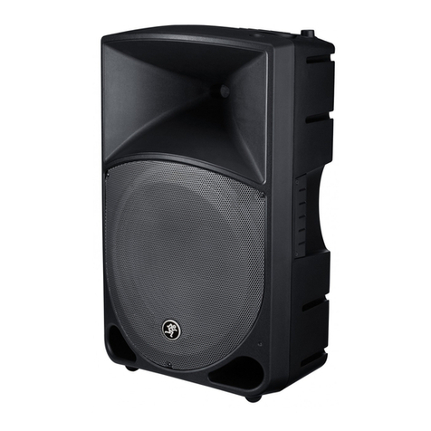
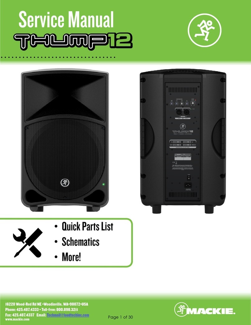
Mackie Thump 12 User manual

OWNER’S MANUAL
1000W Powered Loudspeakers
Thump12 • Thump15

Thump12 • Thump15 Powered Loudspeakers
2
Thump12 • Thump15 Powered Loudspeakers
Important Safety Instructions
1. Read these instructions.
2. Keep these instructions.
3. Heed all warnings.
4. Follow all instructions.
5. Do not use this apparatus near water.
6. Clean only with a dry cloth.
7. Do not block any ventilation openings. Install in accordance
with the manufacturer’s instructions.
8. Do not install near any heat sources such as radiators, heat registers, stoves,
or other apparatus (including amplifiers) that produce heat.
9. Do not defeat the safety purpose of the polarized or grounding-type plug.
A polarized plug has two blades with one wider than the other. A grounding-type
plug has two blades and a third grounding prong. The wide blade or the third prong
are provided for your safety. If the provided plug does not fit into your outlet,
consult an electrician for replacement of the obsolete outlet.
10.Protect the power cord from being walked on or pinched particularly at plugs,
convenience receptacles, and the point where they exit from the apparatus.
11.Only use attachments/accessories specified by the manufacturer.
12.Use only with a cart, stand, tripod, bracket, or table specified
by the manufacturer, or sold with the apparatus. When a
cart is used, use caution when moving the cart/apparatus
combination to avoid injury from tip-over.
13.Unplug this apparatus during lightning storms or when
unused for long periods of time.
14.Refer all servicing to qualified service personnel. Servicing is
required when the apparatus has been damaged in any way, such as power-supply
cord or plug is damaged, liquid has been spilled or objects have fallen into the
apparatus, the apparatus has been exposed to rain or moisture, does not operate
normally, or has been dropped.
15.This apparatus shall not be exposed to dripping or splashing, and no object filled
with liquids, such as vases or beer glasses, shall be placed on the apparatus.
16.Do not overload wall outlets and extension cords as this can result in a risk of fire
or electric shock.
17.This apparatus has been designed with Class-I construction and must be
connected to a mains socket outlet with a protective earthing connection
(the third grounding prong).
18.This apparatus has been equipped with a rocker-style AC mains power switch. This
switch is located on the rear panel and should remain readily accessible to the user.
19. The MAINS plug or an appliance coupler is used as the disconnect device,
so the disconnect device shall remain readily operable.
PORTABLE CART
WARNING
CAUTION
The lightning flash with arrowhead symbol within
an equilateral triangle is intended to alert the user
to the prescence of uninsulated “dangerous voltage”
within the product’s enclosure, that may be of significant
magnitude to constitute a risk of electric shock to persons.
RISK OF ELECTRIC SHOCK! DO NOT OPEN!
CAUTION: TO REDUCE THE RISK OF ELECTRIC SHOCK DO NOT
REMOVE COVER (OR BACK). NO USER-SERVICEABLE PARTS INSIDE.
REFER SERVICING TO QUALIFIED PERSONNEL.
The exclamation point within an equilateral triangle is
intended to alert the user of the prescence of important
operating and maintaining (servicing) instructions in the
literature accompanying the appliance.
WARNING — To reduce the risk of fire or electric
shock, do not expose this apparatus to rain or moisture.
CAUTION — To prevent electric shock hazard, do not
connect to mains power supply while grille is removed.
20. NOTE: This equipment has been tested and found to comply with the limits
for a Class B digital device, pursuant to part 15 of the FCC Rules. These limits
are designed to provide reasonable protection against harmful interference
in a residential installation. This equipment generates, uses, and can radiate
radio frequency energy and, if not installed and used in accordance with the
instructions, may cause harmful interference to radio communications. However,
there is no guarantee that interference will not occur in a particular installation.
If this equipment does cause harmful interference to radio or television reception,
which can be determined by turning the equipment off and on, the user is
encouraged to try to correct the interference by one or more of the following
measures:
• Reorientorrelocatethereceivingantenna.
• Increasetheseparationbetweentheequipmentandthereceiver.
• Connecttheequipmentintoanoutletonacircuitdifferentfromthatto
which the receiver is connected.
• Consultthedealeroranexperiencedradio/TVtechnicianforhelp.
CAUTION: Changes or modifications to this device not expressly approved by
LOUD Technologies Inc. could void the user's authority to operate the equipment
under FCC rules.
21.This apparatus does not exceed the Class A/Class B (whichever is applicable)
limits for radio noise emissions from digital apparatus as set out in the radio
interference regulations of the Canadian Department of Communications.
ATTENTION — Le présent appareil numérique n’émet pas de bruits radioélectriques
dépassant las limites applicables aux appareils numériques de class A/de class B
(selon le cas) prescrites dans le réglement sur le brouillage radioélectrique édicté
par les ministere des communications du Canada.
22.Exposure to extremely high noise levels may cause permanent hearing loss.
Individuals vary considerably in susceptibility to noise-induced hearing loss, but
nearly everyone will lose some hearing if exposed to sufficiently intense noise
for a period of time. The U.S. Government’s Occupational Safety and Health
Administration (OSHA) has specified the permissible noise level exposures shown
in the following chart.
According to OSHA, any exposure in excess of these permissible limits could result
in some hearing loss. To ensure against potentially dangerous exposure to high
sound pressure levels, it is recommended that all persons exposed to equipment
capable of producing high sound pressure levels use hearing protectors while the
equipment is in operation. Ear plugs or protectors in the ear canals or over the
ears must be worn when operating the equipment in order to prevent permanent
hearing loss if exposure is in excess of the limits set forth here:
Duration,
per day in
hours
Sound Level dBA,
Slow Response Typical Example
8 90 Duo in small club
6 92
4 95 Subway Train
3 97
2 100 Veryloudclassicalmusic
1.5 102
1 105 Greg screaming at Troy about deadlines
0.5 110
0.25 or less 115 Loudest parts at a rock concert
Laite on liitettävä suojakoskettimilla varustettuun pistorasiaan.
Apparatet må tilkoples jordet stikkontakt.
Apparaten skall anslutas till jordat uttag.
Correct disposal of this product: This symbol indicates that this product should not be disposed of with your household
waste, according to the WEEE directive (2012/19/EU) and your national law. This product should be handed over to
an authorized collection site for recycling waste electrical and electronic equipment (EEE). Improper handling of this type
of waste could have a possible negative impact on the environment and human health due to potentially hazardous substances
that are generally associated with EEE. At the same time, your cooperation in the correct disposal of this product will
contribute to the effective usage of natural resources. For more information about where you can drop off your waste
equipment for recycling, please contact your local city office, waste authority, or your household waste disposal service.
Owner’s Manual
3
Owner’s Manual
Contents Features
Part No. SW1049 Rev. A 03/14
©2014 LOUD Technologies Inc. All Rights Reserved.
• 1000WTotalSystemPower
•Gig-ready,high-outputdesign
•Ultra-efcientClass-Damplication
• Class-leading,Chest-thumpingLowEnd
•12"high-outputwoofer[Thump12]
•15"high-outputwoofer[Thump15]
•1.4"Titaniumdomecompressiondriver
•Dynamicbassresponsedeliversamazing
lowsatallvolumes
•TotalSystemOptimization
•Precision2-waycrossover
•Transducertimealignment
•Systemprotection/limiting
•ApplicationFlexible
•3-bandEQwithsweepablemidtodial
intheperfectsound
•Mic/lineinputallowsdirectconnection
ofmicrophone
•Flexiblemountingoptionsincludingtripod
andpole-mounting
•Angleddesignperfectforuseasastage
monitor
• LightweightandPortable
•Ruggedpolypropyleneconstruction
designedforheavyuse
•29.0lb/13.2kg[Thump12]
•33.2lb/15.1kg[Thump15]
Like us
Follow us
Watch our dang videos
Please write the serial numbers here for future
reference (i.e., insurance claims, tech support,
return authorization, make dad proud, etc.)
Purchased at:
Date of purchase:
Important Safety Instructions .................................. 2
Contents................................................................. 3
Features................................................................. 3
Introduction............................................................ 4
How To Use This Manual ......................................... 4
Getting Started....................................................... 4
Things To Remember................................................ 4
Hookup Diagrams.................................................... 5
Thump12 / Thump15: Rear Panel Features............... 9
1. Power Connection ......................................... 9
2. Power Switch ............................................... 9
2. Power LED.................................................... 9
4. XLR and 1/4" Combo Inputs.......................... 9
5. Thru Output................................................ 10
6. Level Knob / OL LED................................... 10
7. Low EQ ...................................................... 11
8. Mid EQ....................................................... 11
9. Mid Freq .................................................... 11
10. Hi EQ ....................................................... 11
Final Thoughts ...................................................... 11
Placement............................................................. 11
Care and Maintenance ........................................... 11
Protection Circuitry ............................................... 12
Limiting.......................................................... 12
Overexcursion Protection ................................ 12
Thermal Protection.......................................... 12
AC Power............................................................. 12
Appendix A: Service Information ............................ 13
Appendix B: Connections ....................................... 14
Appendix C: Technical Information .......................... 15
Thump12 / Thump15 Dimensions..................... 16
Thump12 / Thump15 Frequency Response........ 17
Thump12 / Thump15 Block Diagram ................ 18
Limited Warranty.................................................. 19

Thump12 • Thump15 Powered Loudspeakers
4
Thump12 • Thump15 Powered Loudspeakers
Getting Started
Introduction
OnlyThumpPoweredLoudspeakersdeliverthe
class-leading,chest-thumpinglowendyoudeserve.
EachThumploudspeakerdelivers1000wattsofpower,
providingthehigh-outputyouneedinapackagethat’s
tough,lightweightandportable.
Designedbytheworld’sleaderinportablelivesound,
Thumploudspeakersoffera3-bandEQfordialingin
theidealsound.Andwitharuggedenclosureandrobust
systemprotection,you’remorethanreadyforthenext
gig.
Deliveringreal-worldpowerlevels,application
exibilityandclass-leadingbassresponse,youcanbe
condentthatThumploudspeakersoffersthebest
performanceforyourmoney.
How to Use This Manual:
Afterthisintroduction,agettingstartedguidewill
helpyougetthingssetupfast.Thehookupdiagrams
showsometypicalThump12andThump15setups,
includingsomethatinvolvetheThump18Ssubwoofer.
Thisiconmarksinformationthatiscritically
importantoruniquetothesubwoofer.For
yourowngood,readandrememberthem.
Thefollowingstepswillhelpyousetupthe
loudspeakersquickly.
1.Makeallinitialconnectionswiththepower
switchesOFFonallequipment.Makesurethemaster
volume,levelandgaincontrolsareallthewaydown.
2.Ifusingasubwoofer,connecttheoutputsfrom
themixingconsole(orothersignalsource)tothe
inputsontherearpanelofthesubwoofer,thenconnect
thehighpassoutputsfromthesubwoofertotheinputs
oftheloudspeakers.Makesurethesubwoofer’sgain
knobissetto“U”(unitygain).
3.Ifnotusingasubwoofer,connecttheoutputs
fromthemixingconsole(orothersignalsource)
totheinputsontherearpaneloftheloudspeakers.
4.Makesuretheloudspeaker’slevelknobisset
to“U”(unitygain).
5.Pushthelinecordsecurelyintothesubwoofer’s/
loudspeaker’sIECconnectorsandplugtheotherends
intogroundedACoutlets.Thesubwoofer/loudspeaker
mayaccepttheappropriatevoltageasindicatednear
theIECconnector.
6.Turnthemixer(orothersignalsource)on.
7.Turnthesubwooferon.
8.Turntheloudspeakerson.
9.Startthesignalsourceandraisethemixer’s
mainL/Rfaderuptoacomfortablyloudlisteninglevel.
Things to Remember:
• Neverlistentoloudmusicforprolongedperiods.
PleaseseetheSafetyInstructionsonpage2for
informationonhearingprotection.
• Asageneralguide,themixer(orothersignal
source)shouldbeturnedonrst,subwoofers
next,andThumploudspeakerslast.Assuch,
theThumploudspeakersshouldalsobeturnedoff
rst,followedbythesubwoofers,thenthemixer.
Thiswillreducethepossibilityofanyturn-on
orturn-offthumpsandothernoisesgenerated
byanyupstreamequipmentfromcomingoutof
thespeakers.
• Savetheshippingboxesandpackingmaterials!
Youmayneedthemsomeday.Besides,the
catswillloveplayinginthemandjumpingoutat
youunexpectedly.Remembertopretendlikeyou
aresurprised!
• Saveyoursalesreceiptinasafeplace.

Owner’s Manual
5
Owner’s Manual
Small Club System
13DELAY1 (300ms)
14DELAY2 (380ms)
15DELAY3 (480ms)
16REVERB+DLY (250ms)
8K4K2K1K500250125
15
15
10
10
5
5
0
15
15
10
10
5
5
0
TAPE
IN
STRETURN MAINOUT PHONES
FOOTSWITCH
PHONES
TAPE
OUT
L
R
L
(UNBALANCED)
R
0dB=0dBu
MAIN
METERS
RL
OL
4
6
3
10
15
7
10
20
30
0
2
BREAK
(MUTESALLCHANNELS)
PHANTOM
POWER
POWER
STEREOGRAPHIC EQ
FXSEND
MID
2.5kHz
MID
2.5kHz
MID
2.5kHz
MID
2.5kHz
MID
2.5kHz
80Hz
LOW
U
+15-15
U
+15-15
U
+15-15
INSERT
RL
LOWCUT
100Hz
U
GAIN
M
I
C
G
A
I
N
U+50
-20dB +30dB
OL
1
EQ
12kHz
HI
PAN
AUX
U
+15
OO
MON
FX
U
+15
OO
80Hz
LOW
U
+15-15
U
+15-15
U
+15-15
RL
LOWCUT
100Hz
U
GAIN
M
I
C
G
A
I
N
U+50
-20dB +30dB
2
EQ
12kHz
HI
PAN
AUX
U
+15
OO
MON
FX
U
+15
OO
80Hz
LOW
U
+15-15
U
+15-15
U
+15-15
LINEIN2LINE/HI-ZIN1
INSERT
BAL/
UNBAL
(MONO) (MONO) (MONO) (MONO)
LINEIN3
LINEIN4
BAL/
UNBAL LINEIN5
RL
LOWCUT
100Hz
GAIN
3/4
EQ
12kHz
HI
PAN
AUX
U
+15
OO
MON
FX
U
+15
OO
80Hz
LOW
U
+15-15
U
+15-15
U
+15-15
RL
LOWCUT
100Hz
GAIN
M
I
C
G
A
I
N
U+50
M
I
C
G
A
I
N
U+50
5/6
EQ
12kHz
HI
LEVEL
SET
LEVEL
SET
LEVEL
SET
LEVEL
SET
PAN
AUX
U
+15
OO
MON
FX
U
+15
OO
GAIN
MICMICMICMIC
80Hz
LOW
U
+15-15
U
+15-15
U
+15-15
U
+20-20
RL
7/8 STRTN FX RTN
EQ
12kHz
HI
PAN
AUX
U
+15
OO
MON
FX
U
+15
OO
U
+15
FXTO MON
FXMASTER
U
+15
OO
OO
dB
30
20
10
10
OO
40
50
5
5
U
60
dB
30
20
10
10
OO
40
50
5
5
U
60
dB
30
20
10
10
OO
40
50
5
5
U
60
dB
30
20
10
10
OO
40
50
5
5
U
60
dB
30
20
10
10
OO
40
50
5
5
U
60
dB
30
20
10
10
OO
40
50
5
5
U
60
dB
30
20
10
10
OO
40
50
5
5
U
60
dB
30
20
10
10
OO
40
50
5
5
U
60
dB
30
20
10
10
OO
40
50
5
5
U
60
L
R
LINEIN6
BAL/
UNBAL
L
R
LINEIN7
LINEIN8
BAL/
UNBAL
L
R
BAL/
UNBAL
L
R
BAL/
UNBAL
L
R
MONSEND
BAL/
UNBAL
BAL/
UNBAL
MUTE
PRESETS
FXPRESETS
OL OL OL OL OL
INPUTLEVEL
USB
OO
+20
U
TAPELEVEL
OO
+20
U
MON MAIN
1 2 3/4 5/6 7/8
OL
USB THRU
LINE
HI-Z
MAINMIX
MON
EQIN
BYPASS
01BRIGHTROOM
02WARMLOUNGE
03SMALLSTAGE
04WARMTHEATER
05WARMHALL
06CONCERTHALL
07PLATEREVERB
08CATHEDRAL
09CHORUS
10CHORUS+REV
11DOUBLER
12TAPESLAP
OO
MAX
LINE
HI-Z
MUTE MUTE MUTE MUTE MUTE MUTE
48V
PROFESSIONALMIC/LINE MIXER WITH FX
In this example, a ProFX8 mixer is connected directly to two Thump12 loudspeakers. It is the perfect
setup for a small club. Simply connect the L/R outputs of the ProFX8 mixer to the inputs of each
Thump12 loudspeaker.
If you desire a little more boom, add a Thump18S subwoofer to the mix. Here, the L/R outputs of a
ProFX8 mixer are connected directly to the channel A and B inputs of a single Thump18S subwoofer.
The channel A and B high pass outputs of the Thump18S subwoofer are connected directly to the inputs
of each Thump12 loudspeaker.
Hookup Diagrams

Thump12 • Thump15 Powered Loudspeakers
6
Thump12 • Thump15 Powered Loudspeakers
DJ System
O
N
Y
X
M
I
C
P
R
E
LR
2 1
MONITOROUT
BAL/UNBAL
USB
BAL/UNBAL
O
N
Y
X
M
I
C
P
R
E
Hookup Diagrams continued...
Perhaps you’re a DJ playing bumpin’ tunes in the middle of the night to a crowd that’s groovin’
and dancin’ to your fine selection.
In this example, a laptop is connected to the channel 1 and 2 inputs of an Onyx Blackjack and a set of
headphones are connected to the phones jack.
The L/R monitor outputs of the Onyx Blackjack are connected directly to the channel A inputs of each
Thump18S subwoofer.
The channel A high pass output of each Thump18S subwoofer is connected directly to the input of each
Thump15 loudspeaker.

Owner’s Manual
7
Owner’s Manual
Daisy-Chaining Multiple Thump Loudspeakers
Hookup Diagrams continued...
1402VLZ4 Mixer
To next
Thump
loudspeaker
input
To next
Thump
loudspeaker
input
Main
Outs
To next
Thump
loudspeaker
input
Thump loudspeakers may be daisy-chained via the male XLR connector labeled “THRU”. Simply plug
the signal source (i.e., mixer output or microphone) into the input jack(s), and patch that loudspeaker’s
thru jack to the next loudspeaker’s input jack, and so on, daisy-chaining multiple Thump loudspeakers.
See above for visual representations of daisy-chaining.

Thump12 • Thump15 Powered Loudspeakers
8
Thump12 • Thump15 Powered Loudspeakers
Large Club System
Hookup Diagrams continued...
Here’s how to set up a large club system. In this example, the L/R outputs of a DL1608 mixer are
connected directly to the channel A inputs of two Thump18S subwoofers. The channel A full range
outputs of these two Thump18S subwoofers are connected directly to the channel A inputs of another
set of Thump18S subwoofers. Talk about beefy low end...and we’ve only connected the subs!
The channel A high pass outputs of the last two Thump18S subwoofers are connected directly to the
inputs of the main pair of Thump15 loudspeakers.
The aux 1 and aux 2 sends from the mixer are connected directly to the inputs of a pair of Thump12
loudspeakers to be used as monitors for the band.

Owner’s Manual
9
Owner’s Manual
Thump12 / Thump15 Loudspeakers: Rear Panel Features
1.Power Connection
Thisisastandard3-prongIECpowerconnector.
Connectthedetachablepowercord(includedin
thepackagingwiththeloudspeaker)tothepower
receptacle,andplugtheotherendofthepower
cordintoanACoutlet.
MakesurethattheACpowerismatchedto
theACpowerindicatedontherearpanel
(belowtheIECreceptacle).
Disconnectingtheplug’sgroundpinis
dangerous.Don’tdoit!
2.Power Switch
Pressthetopofthisrockerswitchinwardstoturnon
theloudspeaker.Pressthebottomofthisrockerswitch
inwardstoturnofftheloudspeaker.
Asageneralguide,themixer(orother
signalsource)shouldbeturnedonrst,
subwoofersnext,andloudspeakerslast.
Assuch,theloudspeakersshouldalsobeturned
offrst,followedbythesubwoofers,thenthemixer.
Thiswillreducethepossibilityofanyturn-onor
turn-offthumpsandothernoisesgeneratedbyany
upstreamequipmentfromcomingoutofthespeakers.
3.Power LED
Whenthepowerswitchisturnedon–andthepower
cordisconnectedtoanactiveACmainssupply–this
LEDilluminatesgreentoindicatethattheloudspeaker
isindeedreallyon.ThecoolgreenLEDonthefrontof
theloudspeakerworksthesameway.
4.XLR and 1/4" Combo Inputs
TheinputonThumploudspeakersisacombojack
thatmayacceptbalanced/unbalancedXLRand1/4"
connections.Theinputmayhandleanythingfroma
microphonetoaline-levelsignalsuchasfromamixer.
SimplyconnectanXLR,TRSorTSconnectorintothe
channelandadjustthelevelaccordingly.
NEVERconnecttheoutputofanamplier
directlytotheinputoftheloudspeaker.
Thiscoulddamagetheinputcircuitry
oftheactiveloudspeaker.
XLRconnectorsarewiredasfollows,accordingto
standardsspeciedbytheAES(AudioEngineering
Society):
Balanced XLR Input Connector
Pin1–Shield(ground)
Pin2–Positive(+orhot)
Pin3–Negative(–orcold)
2
31
SHIELD
COLD
HOT
SHIELD
COLD
HOT
3
2
1
Balanced XLR Input Connector
2
3
11
67 8 109
5 4
1

Thump12 • Thump15 Powered Loudspeakers
10
Thump12 • Thump15 Powered Loudspeakers
Thump12 / Thump15 Loudspeakers: Rear Panel Features continued...
Toconnectabalancedlinetothisinput,usea
1/4"Tip-Ring-Sleeve(TRS)plug.“TRS”standsfor
Tip-Ring-Sleeve,thethreeconnectionpoints
availableonastereo1/4"orbalancedphonejack
orplug.TRSjacksandplugsareusedforbalanced
signalsandstereoheadphonesandarewiredasfollows
accordingtostandardsspeciedbytheAES(Audio
EngineeringSociety):
Balanced 1/4" TRS Connector
Sleeve–Shield(ground)
Tip–Positive(+orhot)
Ring–Negative(–orcold)
Toconnectanunbalancedlinetothisinput,usea
1/4"mono(TS)phoneplug,wiredasfollowsaccording
tostandardsspeciedbytheAES(AudioEngineering
Society):
Unbalanced 1/4" TS Connector
Sleeve–Shield(ground)
Tip–Positive(+orhot)
Formoreinformationontheseconnectors,see
AppendixBonpage14.
SLEEVE
TIP
SLEEVE
TIP
RING
RING
TIP
SLEEVERING
Balanced 1/4" TRS Connector
SLEEVE
TIP
TIP
SLEEVE
TIP
SLEEVE
Unbalanced 1/4" TS Connector
5. Thru Output
ThisisamaleXLR-typeconnectorthatproduces
exactlythesamesignalthatisconnectedtotheinput
jack.Useittodaisy-chainseveralThumploudspeakers
togetheroffthesamesignalsource(s).
Theyarewiredasfollows,accordingtostandards
speciedbytheAES(AudioEngineeringSociety):
Balanced XLR Output Connector
Pin1–Shield(ground)
Pin2–Positive(+orhot)
Pin3–Negative(–orcold)
Seepage7tolearnmoreaboutdaisy-chainingThump
loudspeakers.
Formoreinformationontheseconnectors,see
AppendixBonpage14.
6. Level Knob / OL LED
Thelevelknobadjuststheoverallsignallevelatthe
inputtothebuilt-inpowerampliers.ItrangesfromOff
(– )toMAX(maximumgain),withunitygainatthe
centerposition(12o’clock).
•Thumploudspeakersaredesignedtooperatewitha
+4dBusignalwhenthelevelknobisattheU(center)
position.
•Thumploudspeakersmayacceptuptoa+20dBu
signalbyturningdownthelevelknobaccordingly.
Turningthelevelknobpastunitywillprovideenough
gaintoconnectamicrophonedirectly.
NEVERconnecttheoutputofanamplier
directlytotheinputoftheloudspeaker.
Thiscoulddamagetheinputcircuitry
oftheactiveloudspeaker.
TheaccompanyingOL(overload)indicator
illuminatesredwhentheamplierintheThump
loudspeakerisneartheclippingpoint.ItisOKif
theOLLEDblinksoccasionally,becausethismeans
thatthetransientpeaksarejustreachingthemaximum
outputoftheamplierandyouaregettingthemost
outoftheloudspeaker.
2
1
SHIELD
COLD
HOT
3
SHIELD
COLD
HOT
3
2
1
Balanced XLR Output Connector
11
67 8 9 10
5 4

Owner’s Manual
11
Owner’s Manual
Thump12 / Thump15 Loudspeakers: Rear Panel Features continued...
However,iftheOLLEDisblinkingfrequently
orcontinuously,turndownthelevelcontrolonthe
Thumploudspeakerorturndownthesignalatits
source(e.g.,themixingconsole)untiltheOLLED
blinksoccasionallyornotatall.
7. Low EQ
Thiscontrolprovidesupto6dBofboostorcutbelow
80Hzanditisalsoatatthecenterposition(U).
Thisfrequencyrangerepresentsthepunchinbass
drums,bassguitar,fatsynthpatches,andsomereally
seriousmalesingers.
8. Mid EQ
ThisisamidrangeEQcontrolthatprovides6dB
ofboostorcutcenteredatanyfrequencybetween
100Hzand8kHz.TheMIDEQcircuitisat
(noboostorcut)atthecenterposition(U).
Thisfrequencyrangeincludesmostvocals(male
atthelowerendoftherangeandfemaleattheupper
endoftherange),andthefundamentalsandharmonics
formanyinstruments.
9. Mid Freq
Thisknobrangesfrom100Hzto8kHzand
determinesthecenterfrequencyfortheMidEQlter.
Thisallowsyoutozeroinontheprecisebandof
frequenciesyouwanttohaveaffectedbytheMidEQ.
10. Hi EQ
Thiscontrolgivesyouupto6dBboostorcutabove
12kHz.Thecircuitisat(noboostorcut)atthe
centerposition(U).Useittoaddsizzletocymbals,
andanoverallsenseoftransparencyoredgetothe
keyboards,vocals,guitar,andbaconfrying.Turnit
downalittletoreducesibilance,ortoremovehigh
frequencyhiss.
11. Suggested EQ Settings
Youmightpreferadifferentoveralltonedepending
onhowyouwillbeusingtheThumploudspeakers.
TheyareperfectforgeneralPAusewiththe3-bandEQ
setat(allknobsat12o’clock).Forothercommon
applications,settheEQknobsasshown,thenadjust
totastefromthere.
Final Thoughts
ThefollowingpagesdiscussThumploudspeaker
placement,protectioncircuitry,technicalinformation
andmuchmore.Checkitout!
Placement
Thumploudspeakersaredesignedtositonthe
oororstage.Theymayalsobepole-mountedvia
thebuilt-insocketonthebottomofthecabinet.
Theyarenotdesignedtobesuspended.
Whenpole-mountingThumploudspeakers,besure
thatthesubwoofersarestabilizedandsecuredfrom
fallingoverorbeingaccidentallypushedover.For
stackedscenarios,itishighlysuggestedthatstrapsare
utilized.Failuretofollowtheseprecautionsmayresult
indamagetotheequipment,personalinjury,ordeath.
Thumploudspeakercabinetshavenorigging
pointsandarenotsuitableforrigging.NEVER
attempttosuspendaThumploudspeakerby
itshandles.
Aswithanypoweredcomponents,protectthemfrom
moistureandextremecoldandfollowtheotherCare
andMaintenancesuggestionsbelow.
Care and Maintenance
YourThumploudspeakerswillprovidemanyyearsof
reliableserviceifyoufollowtheseguidelines:
• Avoidexposingtheloudspeakerstomoisture.
Iftheyaresetupoutdoors,besuretheyare
undercoverifrainisexpected.
• Avoidexposuretoextremecold(below
freezingtemperatures).Ifyoumustoperate
theloudspeakersinacoldenvironment,warm
upthevoicecoilsslowlybysendingalow-level
signalthroughthemforabout15minutesprior
tohigh-poweroperation.
• Useadryclothtocleanthecabinets.Onlydo
thiswhenthepoweristurnedoff.Avoidgetting
moistureintoanyoftheopeningsofthe
cabinet,particularlywherethedriversare
located.

Thump12 • Thump15 Powered Loudspeakers
12
Thump12 • Thump15 Powered Loudspeakers
Protection Circuitry
Thumploudspeakersemployabuilt-inlimiterfor
lessdistortionatpeaklevels.Adynamicbassresponse
circuitprovidesoptimallowfrequencyresponse
regardlessofoveralloutputlevel.Additionalprotection
includesautomaticthermalshutdownshouldtheamp
overheat.However,withClass-Damptechnology,which
ishighly-efcient,thisshouldneverbeaproblem.
Theprotectioncircuitsaredesignedto
protecttheloudspeakersunderreasonable
andsensibleconditions.Shouldyouchoose
toignorethewarningsigns[e.g.excessivedistortion],
youcanstilldamagethespeakerintheloudspeaker
byoverdrivingitpastthepointofamplierclipping.
Suchdamageisbeyondthescopeofthewarranty.
Limiting
Thedriverhasitsowncompressioncircuitwhich
helpsprotectitfromdamagingtransientpeaks.
Thecompressorisdesignedtobetransparentand
isnotnoticeableundernormaloperatingconditions.
Overexcursion Protection
Asubsonicltercircuitjustpriortothepowerampli-
erpreventsultra-lowfrequenciesfrombeingamplied.
Excessivelow-frequencyenergycandamagethewoofer
bycausingitto“bottomout,”alsoknowasoverexcur-
sion,whichisequivalenttoamechanicalformofclip-
ping.
Thermal Protection
Allampliersproduceheat.Thumploudspeakersare
designedtobeefcientbothelectricallyandthermally.
Intheunlikelyeventoftheamplieroverheating,
abuilt-inthermalswitchwillactivate,mutingthe
signal.
Whentheamplierhascooleddowntoasafe
operatingtemperature,thethermalswitchresets
itself,andtheThumploudspeakerresumesnormal
operation.
Ifthethermalswitchactivates,tryturningdown
thelevelcontrolanotchortwoonthemixingconsole
(orthebackoftheloudspeaker)toavoidoverheating
theamplier.Beawarethatdirectsunlightand/or
hotstagelightsmaybetheculpritofanamplier
overheating.
AC Power
BesuretheThumploudspeakerispluggedinto
anoutletthatisabletosupplythecorrectvoltage
speciedforyourmodel.Itwillcontinuetooperate
atlowervoltages,butwillnotreachfullpower.
Besuretheelectricalservicecansupplyenough
amperageforallthecomponentsconnectedtoit.
Werecommendthatastiff(robust)supplyofAC
powerbeusedbecausetheampliersplacehigh
currentdemandsontheACline.Themorepowerthat
isavailableontheline,thelouderthespeakerswillplay
andthemorepeakoutputpowerwillbeavailablefor
acleaner,punchierbass.Asuspectedproblemof“poor
bassperformance”isoftencausedbyaweakACsupply
totheampliers.
Neverremovethegroundpinonthepower
cordoranyothercomponentoftheThump
loudspeaker.Thisisverydangerous.

Owner’s Manual
13
Owner’s Manual
Appendix A: Service Information
Poor sound
• Isitloudanddistorted?Makesurethatyou’renot
overdrivingastageinthesignalchain.Verifythat
alllevelcontrolsaresetproperly.
• Istheinputconnectorpluggedcompletelyinto
thejack?Besureallconnectionsaresecure.
Noise
• Makesureallconnectionstotheactive
loudspeakersaregoodandsound.
• Makesurenoneofthesignalcablesarerouted
nearACcables,powertransformers,orother
EMI-inducingdevices.
• IstherealightdimmerorotherSCR-based
deviceonthesameACcircuitastheThump
loudspeaker?UseanAClinelterorplugthe
loudspeakerintoadifferentACcircuit.
Hum
• Trydisconnectingthecableconnectedtothe
inputjack.Ifthenoisedisappears,itcouldbe
a“groundloop,”ratherthanaproblemwiththe
Thumploudspeaker.Trysomeofthefollowing
troubleshootingideas:
• Usebalancedconnectionsthroughoutyoursystem
forthebestnoiserejection.
• Wheneverpossible,plugalltheaudioequipment’s
linecordsintooutletswhichshareacommon
ground.Thedistancebetweentheoutletsandthe
commongroundshouldbeasshortaspossible.
Repair
Forwarrantyservice,refertothewarranty
informationonpage19.
Non-warrantyserviceisavailableatafactory-
authorizedservicecenter.Tolocatethenearest
servicecenter,visitwww.720trees.com,click“Contact
TechSupport”andselect“LocateaServiceCenter
orDistributor”[3].ServiceforThumploudspeakers
outsidetheUnitedStatescanbeobtainedthroughlocal
dealersordistributors.
Ifyoudonothaveaccesstoourwebsite,youmaycall
theTechSupportdepartmentat1-800-898-3211,
Monday-Friday,duringnormalbusinesshours,Pacic
Time,toexplaintheproblem.TechSupportwilltellyou
wherethenearestfactory-authorizedservicecenteris
locatedinyourarea.
IfyouthinkyourThumploudspeakerhasaproblem,
pleasecheckoutthefollowingtroubleshootingtipsand
doyourbesttoconrmtheproblem.VisittheSupport
sectionofourwebsite(www.720trees.com)whereyou
willndlotsofusefulinformationsuchasFAQsand
otherdocumentation.Youmayndtheanswertothe
problemwithouthavingtopartwithyoursubwoofer.
Troubleshooting
No power
• Ourfavoritequestion:Isitpluggedin?Makesure
theACoutletislive[checkwithatesterorlamp].
• Ournextfavoritequestion:Isthepowerswitch
on?Ifnot,tryturningiton.
• Makesurethelinecordissecurelyseatedinthe
linecordsocketandpluggedallthewayintothe
ACoutlet.
• IsthepowerLEDonthefrontandrearpanel
illuminated?Ifnot,makesuretheACoutlet
islive.Ifso,referto“Nosound”below.
• TheinternalAClinefusemaybeblown.Thisis
notauserserviceablepart.Ifyoususpectthe
AClinefuseisblown,pleaseseethe"Repair"
sectionnext.
No sound
• Isthelevelknobfortheinputsourceturnedall
thewaydown?Verifythatallthevolumecontrols
inthesystemareproperlyadjusted.Lookatthe
levelmetertoensurethatthemixerisreceiving
asignal.
• Isthesignalsourceworking?Makesurethe
connectingcablesareingoodrepairandsecurely
connectedatbothends.Makesuretheoutput
levelcontrolonthemixingconsoleisturnedup
sufcientlytodrivetheinputsofthespeaker.
• Makesurethemixerdoesnothaveamuteonora
processorloopengaged.Ifyoundsomethinglike
this,makesurethelevelisturneddownbefore
disengagingtheoffendingswitch.
• Hasitshutdown?Makesurethereisatleast
sixinchesoffreespacebehindeachThump
loudspeaker.

Thump12 • Thump15 Powered Loudspeakers
14
Thump12 • Thump15 Powered Loudspeakers
Appendix B: Connections
XLR and 1/4" Combo Input Connector
TheinputonThumploudspeakersisacombojack
thatmayacceptbalanced/unbalancedXLRand1/4"
connections.Theinputmayhandleanythingfroman
instrumentleveltoahigh-outputmicsignal.Simply
connectanXLR,TRSorTSconnectorintothechannel
andadjustthelevelaccordingly.
Balanced XLR Input Connector
IfusingbalancedXLRinputcables,besurethe
cablesarewiredperAES(AudioEngineeringSociety)
standards:
Balanced XLR Input Connector
Pin1–Shield(Ground)
Pin2–Positive(+orhot)
Pin3–Negative(–orcold)
Balanced 1/4" TRS Input Connector
Toconnectabalancedlinetothisinput,usea
1/4"Tip-Ring-Sleeve(TRS)plug.“TRS”standsfor
Tip-Ring-Sleeve,thethreeconnectionpoints
availableonastereo1/4"orbalancedphonejack
orplug.
Ifusingbalanced1/4"TRSinputcables,besurethe
cablesarewiredperAES(AudioEngineeringSociety)
standards:
Balanced 1/4" TRS Connector
Sleeve–Shield(ground)
Tip–Positive(+orhot)
Ring–Negative(–orcold)
Balanced XLR Input Connector
2
31
SHIELD
COLD
HOT
SHIELD
COLD
HOT
3
2
1
SLEEVE
TIP
SLEEVE
TIP
RING
RING
TIP
SLEEVERING
Balanced 1/4" TRS Connector
Unbalanced 1/4" TS Input Connector
Toconnectanunbalancedlinetothisinput,usea
1/4"mono(TS)phoneplug.
Ifusingunbalanced1/4"TSinputcables,besurethe
cablesarewiredperAES(AudioEngineeringSociety)
standards:
Unbalanced 1/4" TS Connector
Sleeve–Shield(ground)
Tip–Positive(+orhot)
Balanced XLR Output Connector
ThereisalsoonemalebalancedXLRoutput
connectoroneachThumploudspeaker.Besurethe
cablesarewiredperAES(AudioEngineeringSociety)
standards:
Balanced XLR Output Connector
Pin1–Shield(Ground)
Pin2–Positive(+orhot)
Pin3–Negative(–orcold)
Thumploudspeakersmaybedaisy-chainedviathe
maleXLRconnectorlabeled“THRU”.Simplyplugthe
signalsource(i.e.,mixeroutput)intotheinputjack(s),
andpatchthatloudspeaker’sthrujacktothenext
loudspeaker’sinputjack,andsoon,daisy-chaining
multipleThumploudspeakers.Seepage7foravisual
representationofdaisy-chaining.
SLEEVE
TIP
TIP
SLEEVE
TIP
SLEEVE
Unbalanced 1/4" TS Connector
Balanced XLR Output Connector
2
1
SHIELD
COLD
HOT
3
SHIELD
COLD
HOT
3
2
1

Owner’s Manual
15
Owner’s Manual
Thump12 / Thump15 Loudspeakers Specifications
Appendix C: Technical Information
Line Input Power
US: 100 – 120 VAC,
50 – 60 Hz 130 watts
EU: 220 – 240 VAC,
50 – 60 Hz 130 watts
AC Connector: 3-pin IEC 250 VAC,
10 A male
Safety Features
Peak and RMS limiting, power supply and amplifier thermal
protection
Construction Features
Basic Design: Trapezoidal
Material: Polypropylene
Finish: Textured
Handles: One on each side, one on top
Grille: Perforated metal with
weather-resistant coating
Display LEDs
Front: Power ON
Rear: Power ON, OL (overload)
Operating Temperature: 0 – 40 ˚C
32 – 104 ˚F
Physical Properties
Thump12:
Height: 23.5 in / 596 mm
Width: 14.5 in / 367 mm
Depth: 12.4 in / 314 mm
Weight: 29.0 lb / 13.2 kg
Thump15:
Height: 27.6 in / 702 mm
Width: 16.8 in / 427 mm
Depth: 15.5 in / 394 mm
Weight: 33.2 lb / 15.1 kg
Mounting Methods:
Pole-mountable via the built-in socket on the bottom of the
cabinet. Be sure the pole is capable of supporting the weight
of the Thump loudspeaker.
Options
Thump12 Bag P/N 2036809-07
Thump15 Bag P/N 2036809-06
SPM200 Loudspeaker Pole Mount P/N 2035170-01
Acoustic Performance
Frequency Range (–10 dB): 50 Hz – 23 kHz [Thump12]
32 Hz – 23 kHz [Thump15]
Frequency Range (–3 dB): 57 Hz – 20 kHz [Thump12]
39 Hz – 20 kHz [Thump15]
Horizontal Coverage Angle: 90º
Vertical Coverage Angle: 60º
Maximum SPL Peak: 125 dB SPL @ 1m [Thump12]
126 dB SPL @ 1m [Thump15]
Monitor Angle 50˚ [Thump12]
45˚ [Thump15]
Transducers
Low Frequency: 12 in / 305 mm [Thump12]
15 in / 381 mm [Thump15]
with steel frame, paper cone woofer
High Frequency: 1.4 in / 36 mm Titanium dome
compression driver
Power Amplifiers
Low Frequency Power Amplifier
Rated Power: 400 watts rms
800 watts peak
Design: Class D
High Frequency Power Amplifier
Rated Power: 100 watts rms
200 watts peak
Design: Class AB
Input/Output
Input Type: Female XLR / 1/4" Balanced
Input Impedance: 20 k balanced bridging;
10 k unbalanced
Thru: Male XLR Balanced
Level Control: Rotating knob
0 dB at center
Sensitivity: +4 dBu for full output
(Level Control @ Center)
–36 dBu for full output
(Level Control @ Max)
Electronic Crossover
Crossover Type: 24 dB/octave
Crossover Frequency: 3 kHz
Equalization
Low Frequency EQ: ±6 dB @ 80 Hz, shelving
Mid Frequency EQ: ±6 dB sweepable from
100 Hz to 8 kHz
High Frequency EQ: ±6 dB @ 12 kHz, shelving

Thump12 • Thump15 Powered Loudspeakers
16
Thump12 • Thump15 Powered Loudspeakers
Thump12 Loudspeaker Dimensions
Thump15 Loudspeaker Dimensions
12.4 in
314 mm
14.5 in
367 mm 6.0 in
152 mm
23.5 in
596 mm 23.5 in
596 mm
12.4 in
314 mm
WEIGHT
29.0 lb
13.2 kg
15.5 in
394 mm
16.8 in
427 mm
5.9 in
150 mm
27.6 in
702 mm 27.6 in
702 mm
15.5 in
394 mm
WEIGHT
33.2 lb
15.1 kg
Disclaimer
Since we are always striving to make our products better by incorporating new and improved materials, components, and manufacturing
methods, we reserve the right to change these specifications at any time without notice.
The “Running Man” figure is a registered trademark of LOUD Technologies Inc.
All other brand names mentioned are trademarks or registered trademarks of their respective holders, and are hereby acknowledged.
©2014 LOUD Technologies Inc.
All Rights Reserved.

Owner’s Manual
17
Owner’s Manual
Thump12 Loudspeaker Frequency Response
Thump15 Loudspeaker Frequency Response
Frequency (Hz)
20
–20 dB
–30 dB
–10 dB
+10 dB
0 dB
100 1000 20000 10000
Frequency (Hz)
20
–20 dB
–30 dB
–10 dB
+10 dB
0 dB
100 1000 20000 10000

Thump12 • Thump15 Powered Loudspeakers
18
Thump12 • Thump15 Powered Loudspeakers
Thump12 / Thump15 Loudspeakers Block Diagram
HF
LF
Amp
Amp
OL LED
Limiter
Limiter
Mute
Mute
Level
Control
Loudspeaker
Processing
Loudspeaker
Processing
3-Band Contour EQ
80 100-8K 12K
LO MID HI
Thermal
Monitoring
Input
XLR
Loop
Out
XLR

Owner’s Manual
19
Owner’s Manual
Limited Warranty
Please keep your sales receipt in a safe place.
This Limited Product Warranty (“Product Warranty”) is provided by LOUD Technologies Inc. (“LOUD”)
and is applicable to products purchased in the United States or Canada through a LOUD-authorized
reseller or dealer. The Product Warranty will not extend to anyone other than the original purchaser
of the product (hereinafter, “Customer,” “you” or “your”).
For products purchased outside the U.S. or Canada, please visit www.720trees.com to find contact
information for your local distributor, and information on any warranty coverage provided by the
distributor in your local market.
LOUD warrants to Customer that the product will be free from defects in materials and workmanship
under normal use during the Warranty Period. If the product fails to conform to the warranty then LOUD
or its authorized service representative will at its option, either repair or replace any such nonconforming
product, provided that Customer gives notice of the noncompliance within the Warranty Period to the
Company at: www.720trees.com or by calling LOUD technical support at 1.800.898.3211 (toll-free in
the U.S. and Canada) during normal business hours Pacific Time, excluding weekends or LOUD holidays.
Please retain the original dated sales receipt as evidence of the date of purchase. You will need it to obtain
any warranty service.
For full terms and conditions, as well as the specific duration of the Warranty for this product, please
visit www.720trees.com.
The Product Warranty, together with your invoice or receipt, and the terms and conditions located at
www.720trees.com constitutes the entire agreement, and supersedes any and all prior agreements
between LOUD and Customer related to the subject matter hereof. No amendment, modification or
waiver of any of the provisions of this Product Warranty will be valid unless set forth in a written
instrument signed by the party to be bound thereby.
Need help with the loudspeaker?
• Visit www.720trees.com and click Support to find: FAQs, manuals, addendums, and other documents.
• Email us at: [email protected].
• Telephone 1-800-898-3211 to speak with one of our splendid technical support chaps
(Monday through Friday, normal business hours, Pacific Time).

16220 Wood-Red Road NE
Woodinville, WA 98072 • USA
Phone: 425.487.4333
Toll-free: 800.898.3211
Fax: 425.487.4337
www.720trees.com
This manual suits for next models
2
Table of contents
Other Mackie Speakers manuals

Mackie
Mackie iP-10 User manual

Mackie
Mackie SRM350 User manual

Mackie
Mackie SRM450v3 User manual

Mackie
Mackie SRM-Flex User manual

Mackie
Mackie C200 User manual

Mackie
Mackie MR524 User manual

Mackie
Mackie SRM 450 User manual

Mackie
Mackie Thump12A User manual

Mackie
Mackie HR824 User manual

Mackie
Mackie THUMP GO User manual

Mackie
Mackie HR824 User manual

Mackie
Mackie Monitor Series MR3STK User manual

Mackie
Mackie SRM350 User manual

Mackie
Mackie Personal PA User manual

Mackie
Mackie HR824 User manual

Mackie
Mackie HR624 User manual

Mackie
Mackie Thump12 User manual

Mackie
Mackie S225 Maintenance manual

Mackie
Mackie ART300A User manual

Mackie
Mackie mr5mk2 User manual