Made Engineered Romar Leisure Furl furling boom User manual

Owners manual Romar Leisure Furl Rev 0 © Made Engineered BV 2021
Component packing list
OWNER’S MANUAL
Romar Leisure Furl furling boom
The information contained in this handbook is to be
used as a guide for the safe installation, operation and
maintenance of the Leisure furl system.

1
Made Type S | in-boom furling system with manual drive
Owners manual Romar Leisure Furl Rev 0 © Made Engineered BV 2021
Contents
1. Components packing list .................................................................................................................. 2
2. Installation.........................................................................................................................................5
2.1 Preparing the mast ....................................................................................................................5
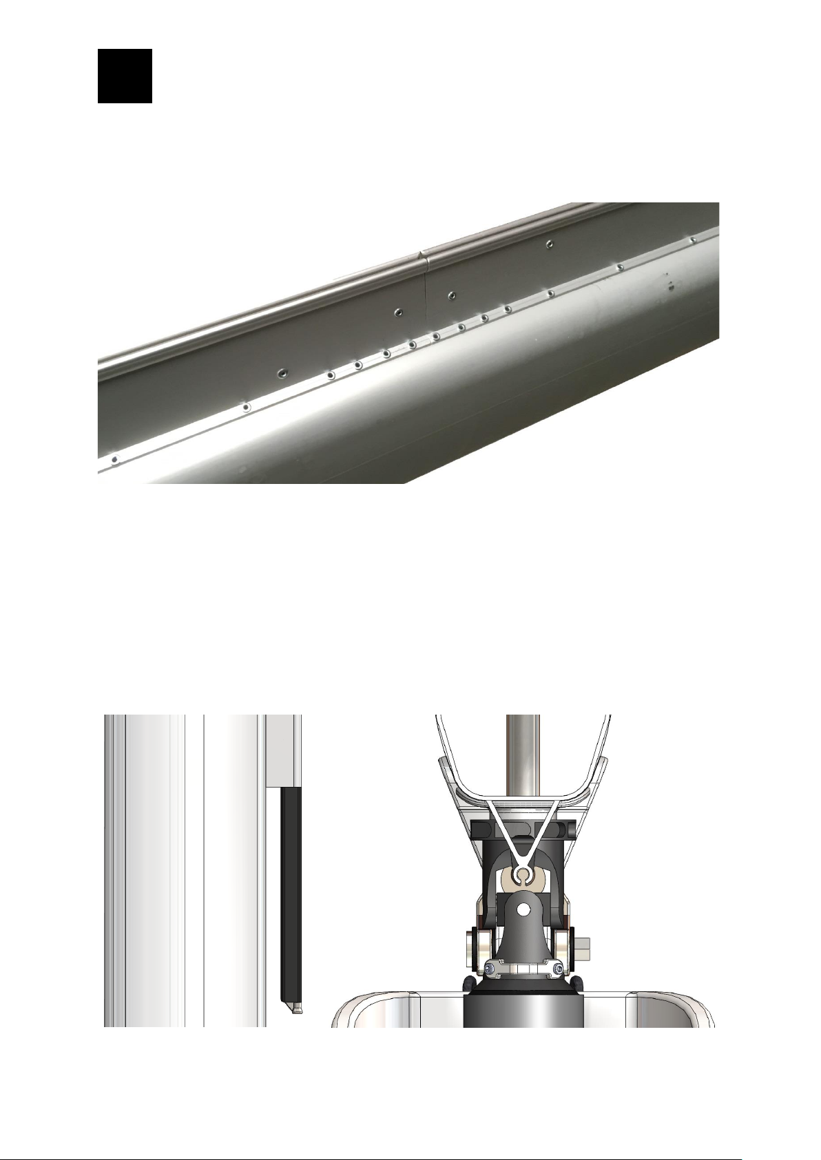
2.2 Fitting the Leisure furl sail track ................................................................................................6
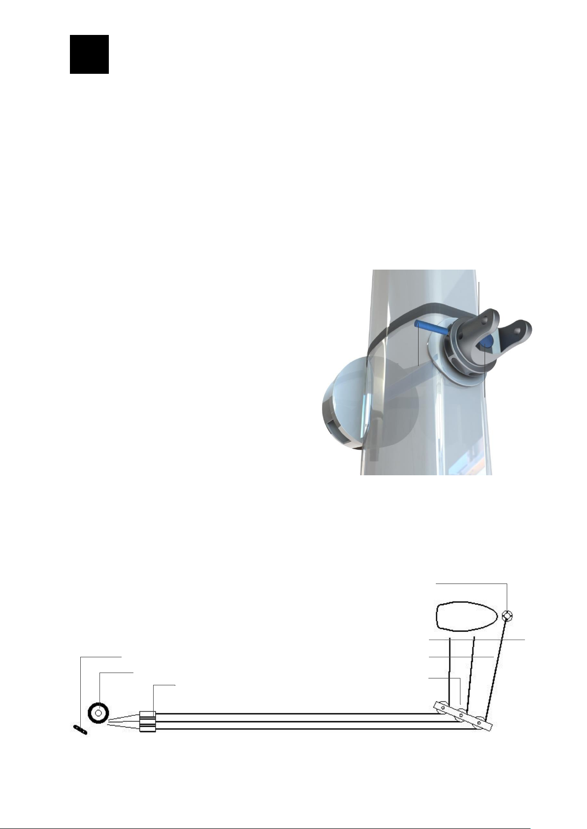
2.3 Fitting the mast components.................................................................................................... 8
2.4 Fitting the boom and mandrel ................................................................................................... 8
2.5 Deck lay-out ............................................................................................................................. 9
2.6 Sail fitting instructions ............................................................................................................ 10
2.7 Checklist after installation ........................................................................................................11
3. Operation ........................................................................................................................................ 12
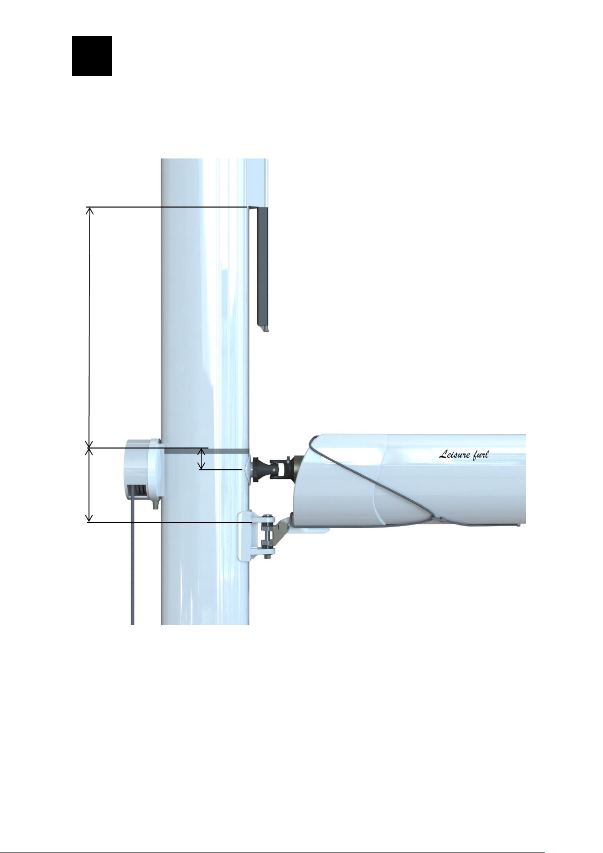
3.1 Setting up boom height............................................................................................................ 12
3.2 Hoisting the sail....................................................................................................................... 13
3.3 Furling the sail ......................................................................................................................... 13
3.4 Controlling the sail................................................................................................................... 14
3.5 Sail adjustments ...................................................................................................................... 16
3.6 Operating tips.......................................................................................................................... 17
3.7 Trouble shooting...................................................................................................................... 18
4. Maintenance................................................................................................................................... 20
5. FAQ.................................................................................................................................................. 21
6. Glossary of terms.............................................................................................................................23
7. Contact details ............................................................................................................................... 24
8. Disclaimer .......................................................................................................................................25

2
Made Type S | in-boom furling system with manual drive
Owners manual Romar Leisure Furl Rev 0 © Made Engineered BV 2021
1. Components packing list
Boom shell
Aluminum or Composite
Mandrel
Aluminum or Composite
Mast track system
Leisure furl track or head car supportable track
Drive system
Manual operation with Dyneema line
Back-up
Back-up recess for winch handle
Sheeting system
Reinforced pad-eyes or tailored solution
Boom vang bracket
Reinforced bracket to match pin and jaw
Support bracket
Internal structure to retain the mandrel
Sail cover
Integrated and retractable sail cover
Topping lift bracket
Stainless steel mounting bracket
LED light
Option
Boom vang
Option

3
Made Type S | in-boom furling system with manual drive
Owners manual Romar Leisure Furl Rev 0 © Made Engineered BV 2021
1.
Furling line
2.
Spool and drum for manual operation with locker and back-up recess
3.
Universal coupling connected to spool with through-mast shaft
4.
Aluminium or carbon fibre furling mandrel
5.
Gooseneck bracket with vertical pin and washers (option)
6.
Gooseneck toggle with horizontal pin and washers
7.
Sail cover retraction line
8.
Retraction line clamp (apply by default)
9.
Reinforced boom vang lug
1
2
3
4
6
7
8
9
5

4
Made Type S | in-boom furling system with manual drive
Owners manual Romar Leisure Furl Rev 0 © Made Engineered BV 2021
10.
Leisure furl luff track or head car supportable luff track
11.
Flexible feeder and pre-feeder
12.
Aluminium or carbon fibre boom shell
13.
Support bracket with rollers and sail cover guides
14.
Integrated retractable sail cover
15.
Topping lift bracket
16.
LED light (option)
17.
Pad-eye(s) for sheet and preventer
10
11
13
14
15
16
17
12

5
Made Type S | in-boom furling system with manual drive
Owners manual Romar Leisure Furl Rev 0 © Made Engineered BV 2021
2. Installation
There are 7 stages to fitting the leisure furl system:
1. Preparing the mast
2. Fitting the sail track
3. Fitting the mast components
4. Fitting the boom and mandrel
5. Deck lay-out
6. Fitting the sail
7. Checklist after installation
Important
▪It is recommended to unstep the mast and position it horizontally (face down) during step 1-3.
▪The area on the aft side of the mast should be clear from obstructions or sharp edges.
▪Before removing or installing any component, check this manual for instructions.
▪The boom should not be raised or lowered more than 10° to its default angle of 90° to the mast.
▪The sail cover retraction line should always be clamped, so it cannot get caught by the sail when furling.
2.1 Preparing the mast
Before any parts are mounted to the mast, first mark the P-measures on the mast. “P” refers to the luff
length of the mainsail.
At the top of the mast, just below the topping lift sheave, mark “TOP P”. Consider the angle the topping lift
will exit at so the topper will clear as the boom articulates. Mark “bottom P” on the mast by measuring the
luff length from “top P”. This mark specifies the sail foot position as well as the top of the furling mandrel.
From “bottom P” set marks at the following positions:
▪X: the distance between “bottom P” and start of luff track
▪Y: distance between “bottom P” and centre of mandrel
▪Z: distance between “bottom P” and the underside of the upper gooseneck lip.

6
Made Type S | in-boom furling system with manual drive
Owners manual Romar Leisure Furl Rev 0 © Made Engineered BV 2021
The exact values for X, Y and Z will be provided on a custom drawing. Ask for this drawing if you have not
received it.
2.2 Fitting the Leisure furl sail track
Position the track on the mast. Use masking tape to secure the track to the mast. Drill on both sides of the
track using a 5 mm drill and fit a Monel rivet to each hole before you drill the next. This way the track will not
move against the mast, misaligning the holes. Ensure the track ends are free from sharp edges and line up
X
Z
Y

7
Made Type S | in-boom furling system with manual drive
Owners manual Romar Leisure Furl Rev 0 © Made Engineered BV 2021
neatly. Luff tape damage could result if misaligned. Drill each track end using 4 rivets on each side at 20
mm centres from the bottom and top edge. Clean all the holes on the mast and radius the edges.
The bottom section of sail track will need cutting to length at the position where the track finishes (mark X).
Once cut to the finished length, deburr the track end and radius the sides carefully. Luff tape damage could
result if the track end is not deburred and the luff groove is not rounded off.
It is essential that the feeder be correctly positioned at all times, so as to ensure the load of the sail is taken
on the feeder, not the sail track. Incorrect alignment may reduce the life of the luff tape, and risks the sail
not entering the sail track correctly.

8
Made Type S | in-boom furling system with manual drive
Owners manual Romar Leisure Furl Rev 0 © Made Engineered BV 2021
2.3 Fitting the mast components
The centre of the shaft that goes through the mast must align with the centre of the mandrel (mark Y). Drill
a hole through the aft side of the mast at mark Y. The diameter of the hole should be slightly larger than the
diameter of the shaft. Deburr the hole on the inside and outside of the mast such that there are no sharp
edges. Drill another hole on the front side of the mast at mark Y in a similar way. The holes must line up
horizontally (90 degree angle to the mast). Again, deburr the hole on the inside and outside of the mast.
Align the aft bearing with the hole on the aft side of the mast and drill and tap according to pattern. It is
advisable to drill, tap and fix the top and bottom hole before you drill, tap and fix the other holes to make
sure everything aligns perfectly. In a similar way, install the drum in front of the mast. Use Tef-Gel to protect
the aluminium mast against the stainless steel bolts.
Position or reposition the gooseneck bracket according to the instructions (mark Z).
2.4 Fitting the boom and mandrel
With the mandrel positioned inside the boom shell and end-bearing, lift the boom into position on the boat.
Preferably, use a crane. Alternatively, use the halyard to lift the front of the boom and use the topper to lift
the aft of the boom, and manoeuvre the front of the boom by hand or with a secured control line to the mast.

9
Made Type S | in-boom furling system with manual drive
Owners manual Romar Leisure Furl Rev 0 © Made Engineered BV 2021
Attach the boom to the gooseneck bracket using the vertical pin. Make sure all washers are in place to avoid
clearance.
It is important to keep the vertical angle between the boom and mast approximately 90 degrees during and
after the installation. This is because the boom and mandrel are installed on the mast independently. So the
mandrel will slide inward when the boom is lowered and outward when the boom is raised. The vertical angle
between the boom and mast must always stay within the range of 80°-100°.
When the boom is mounted, it is advisable first to mount and fix the boom vang in order to unload the topper.
After that, the mandrel can be mounted to the mast.
Slide the universal coupling (with mandrel) onto the
drive shaft until the coupling touches the aft bearing.
The drive shaft should not protrude further than the
opening in the coupling. If the shaft is too long, it will
jam the universal in operation and cause the system
to seize.
To mount the drive shaft to the coupling, fit the pin
through the coupling and shaft. Lock the pin with grub
screws and Loctite.
2.5 Deck lay-out
Consider the lay-out for leading the halyard and furling line aft. The rope guide should lead the furling line
off the spool parallel to the mast from the spool center.
block positioned in line with spool centre athwart ships
topping lift / halyard
organizer
cleat to act as a snub for halyard whilst furling
winch
rope jammers
Furling line
universal coupling
shaft
pin

10
Made Type S | in-boom furling system with manual drive
Owners manual Romar Leisure Furl Rev 0 © Made Engineered BV 2021
It is essential that the mainsail remains visible during both hoist and furl, so position the operating switch
and control lines in the helm in a position to allow this. Generally the winch will be converted to an electric
driven winch or capstan. Use of the rope jammer will determine the position for operation. The operating
switch should be positioned in such a way to allow the operator the freedom to use both hands for managing
the boat. Consider positioning the switch on the helm floor or side wall, and depress the switch using the
foot or knee.
2.6 Sail fitting instructions
With the sail laid on port side, lift the sail foot up towards the furling mandrel. Than slide the foot bolt rope
into the foot track on the mandrel from either forward or aft. Attach first the tack to the furling mandrel,
leaving around 30mm between the tack web and tack ring on the universal. Now lash the clew to the outhaul
saddle on the mandrel. Do not pull the foot out tight, leave fullness in the foot for efficient downwind sailing.
The built-in sail controls will generate outhaul tension. Lash also the clew to the furling mandrel using a
separate lashing, pulling the clew within 10mm of the mandrel.
Use the electrical winch or use the winch handle (inserted into the spool face plate) to roll the sail onto the
port side of the mandrel (clockwise when facing aft). Two persons should assist by pulling either the luff or
leech, so as to ensure the bolt rope remains in the area between the boom edge and the mast, whilst the
sail is being furled.
Alternatively, hoisting the sail from the deck may be preferred, as the boom height from the deck may inhibit
manual fitting. In this instance the furling line will need to be pre-wound on the spool before the sail is
attached - and the boom set to the correct angle for furling - before the sail is hoisted.

11
Made Type S | in-boom furling system with manual drive
Owners manual Romar Leisure Furl Rev 0 © Made Engineered BV 2021
With the sail rolled on the mandrel, fasten one end of the furling line to the spool by first placing 5 turns
around the spool drum in a counter-clock direction, looking aft. Then pass the free end through the hole in
the spool. Tie a single knot as close as possible, and push the knot into the counter bore of the spool drum.
2.7 Checklist after installation
If any of the following points are not complete, the system could be damaged.
1. Ensure the halyard sheave is set correctly, with no chance of chafe on either the halyard or topper.
2. Ensure the track joins are aligned and deburred.
3. Ensure the feeder’s alignment with the sail track is set up correctly.
4. Ensure the spool spins freely.
5. Ensure all machine screws have been treated with anti-corrosive compound.
6. Ensure there are no objects or sharp edges between the feeder and gooseneck for the sail to catch
on.
7. Ensure the drive shaft does not protrude through the back face of the universal drive coupling.
8. Ensure the furling line is lead aft and the rope guide is set correctly for alignment from the deck to
the spool.
9. Ensure the boom angle to mast is not limited by the vang or topper adjustment.
10. Ensure the vang can support the weight of the boom.
11. Never raise or lower the boom more than 10%.

12
Made Type S | in-boom furling system with manual drive
Owners manual Romar Leisure Furl Rev 0 © Made Engineered BV 2021
3. Operation
This section explains:
1. Setting up boom height
2. Hoisting the sail
3. Furling the sail
4. Controlling the sail
5. Adjusting the sail
3.1 Setting up boom height
To establish the correct operating angle for the boom, once at full hoist, over tension the main halyard. This
will give an accurate indication of the tack angle. Pull on the topping lift, tie this off and mark a position for
future reference, as this is the correct position for furling. Release now the topper if interfering with the
mainsail. It is possible for the topper to stretch, so review the height as above regularly.
Release the load of the main halyard until wrinkles appear at the luff. Engage the main halyard jammer, and
mark a position for reference on the main halyard. This position will become the maximum hoist. With the
foot track on the mandrel in its uppermost position, ensure adequate fullness has been allowed for. This
should now be a full and powerful downwind sail.
With the main halyard jammer still engaged, pull on the furling line. This will flatten the foot and tension the
luff, as if an outhaul and cunningham had been applied. This becomes an efficient up wind sail. When the
furling line is released, the mandrel will rotate back to the downwind position (only when the locker is not in
use - disengaged).
Now set up the reef points for the sail:
▪Snub the main halyard around a winch or T cleat, to take the halyard load once the jammer is released.
▪Release the main halyard rope jammer, ensuring load on the halyard is maintained.
▪Pull in on the furling line, as you ease the main halyard. Apply the desired amount of resistance to the
halyard so as to control the amount of “pull back” (see section 3.4: Controlling the sail)
.
▪When each batten is approximately 20mm from the furling mandrel, engage the main halyard rope
jammer, then flatten the sail further by pulling in on the furling line, over tensioning the luff each time.
The batten should lay along the underside of the mandrel, and the sail should flatten along the foot. The

13
Made Type S | in-boom furling system with manual drive
Owners manual Romar Leisure Furl Rev 0 © Made Engineered BV 2021
batten in this position avoids fullness creeping into the foot, so where possible reef on each of the
batten positions.
▪At each of the reef positions mark the main halyard at the jammer position for future height reference.
3.2 Hoisting the sail
Once every 2-3 months we recommend that areas of the bolt rope be coated with Teflon spray, during the
hoist, with special attention given to the head of the sail and the batten ends.
Pre check before hoisting the sail:
▪Guide the sail into the feeder, and attach the main halyard
▪Check that the boom is at the correct angle to the mast
▪Ensure the ratchet lock is disengaged
▪Release the main sheet, and position the yacht head to wind, so as to unload the sail
Sail hoisting:
▪Load the halyard winch with the main halyard and release the furling line rope jammer
▪Proceed to hoist the sail, allowing the furling line to pull lightly through the hand
▪Hoist the sail fully, or to a reef position
▪Lock off the furling line rope jammer
▪Tension the main sheet or bear away and proceed to sail
Controlling sail shape (luff tension & outhaul):
The in-built sail controls allow sail shape to be controlled without the use of a cunningham or outhaul, by
simply tensioning the furling line.
To flatten the sail for upwind conditions:
Lock off the main halyard rope jammer, then over tension the furling line. This rotates the furling mandrel
and draws fullness out of the foot as with an outhaul, at the same time as tensioning the luff as with a
cunningham. Do not adjust the main halyard until such time as you wish to furl the sail below this flattened
position.
3.3 Furling the sail
Check that the boom is at the correct angle to the mast. Release the main sheet, or position the yacht head
to wind, so as to unload the sail.

14
Made Type S | in-boom furling system with manual drive
Owners manual Romar Leisure Furl Rev 0 © Made Engineered BV 2021
▪Snub the main halyard around a winch or T cleat, to take the halyard load once the jammer is released.
▪Release the main halyard rope jammer, ensuring load on the halyard is maintained.
▪Pull in on the furling line, as you ease the main halyard. Apply the desired amount of resistance to the
halyard so as to control the amount of “pull back” (see 3.4 Controlling the sail)
.
▪Once at the desired reef position, engage the main halyard rope jammer, then flatten the sail further by
pulling in on the furling line until the sail is completely flattened.
▪Tension the main sheet or bear away and proceed to sail.
A mandrel locking ratchet has been incorporated into the system so the load can be released from the
furling line. It does not have to be used, but when engaged, can be extremely useful in the following
circumstances:
▪When the sail is to be reefed for a long period of time.
▪In the event of deck gear, or furling line failure, bring the yacht head to wind and lower the sail by hand.
▪Whilst racing the yacht, when an effective outhaul and cunningham is required, it is useful to engage
the ratchet to avoid the creep that will occur. Due to the load on the locker, the system will need to be
unloaded prior to the locker being disengaged.
3.4 Controlling the sail
Pull back is a term used to refer to the sail gradually working back along the mandrel as it is furled and is
visible as lines on the sail, stretching back from the feeder at an angle to the furling mandrel.
A system that is set up and operated correctly will control the amount of pull back and sail shape. Ideally the
sail should always furl neatly and directly under the feeder. Indications that the sail is pulling back
excessively will be visible by lines stretching through the sail from the feeder.

15
Made Type S | in-boom furling system with manual drive
Owners manual Romar Leisure Furl Rev 0 © Made Engineered BV 2021
If the sail shows these signs of substantial pull back, reduce the resistance on the main halyard. You will
immediately notice that the lines of pull back gradually disappear as you continue.
In the instance where the sail works forward, increase the resistance on the main halyard and ensure the
sail is unloaded.

16
Made Type S | in-boom furling system with manual drive
Owners manual Romar Leisure Furl Rev 0 © Made Engineered BV 2021
Do not release the main halyard in spurts. The balance of resistance is essential for efficient furling.
If the sail does not appear to be controllable as explained consider the following
▪The boom height is not set correctly
▪The sail has not been unloaded
▪The sail is not positioned correctly on the mandrel
3.5 Sail adjustments
Small adjustments to perfect the furl can be made as follows:
▪If the sail shows signs of pull back, without resistance on the halyard, make adjustment at the tack (A),
pulling the tack closer into the saddle artificially creates luff round down low. Use the aft tack web if
necessary for greater adjustment. This may cause slight distortion at the luff area around the first
batten.
▪Ease adjustment (C) to return fullness to the foot. Adjustment (B) will not need to be moved from its
original setting.
▪If the sail works forward as it furls, release adjustment (A) approximately 40mm. Leave adjustment (B)
as it is and pull adjustment (C) out by 40mm. Also it may help to pull the topper on a little, past the set
mark before furling.
If these adjustments do not rectify the problem, sail modifications may be required. Contact an authorized
dealer for further assistance.

17
Made Type S | in-boom furling system with manual drive
Owners manual Romar Leisure Furl Rev 0 © Made Engineered BV 2021
3.6 Operating tips
Use of the Ratchet Lock
A ratchet lock is built into the system to enable manual furling, without the fear of a counter rotation. It has
proven useful also when reefed for extended periods. The ratchet will eliminate “creap” which is
experienced on the furling line through stretch, and the rope pulling in on the other turns on the spool. Use
of the ratchet will also remove load from the deck fittings. To disengage the ratchet lock, simply over tighten
the furling line, as you disengage the ratchet lock.
Reef on a batten
Whilst possible to reef at any point of hoist, it remains desirable to reef on a batten as fullness may creep
into the foot, and some efficiency lost for up wind sailing.
Luff tension
Luff tension is essential for efficient sail shape in an up wind heavy weather sail. It is a good idea to over
tension, rather than under tension, as sail shape will suffer in the later circumstance.
Tension with the furling line
The system uses the main halyard as a means of hoisting the sail only. When luff tension is desired we
normally use the furling line. Lock the main halyard off at the desired position, then pull against this with
the furling line to achieve a flatter sail with tensioned luff.
Furling down wind
If it is necessary to furl down wind, we introduce a modified procedure to section 3.3 (Furling the sail):
▪Square away to a broad reach, or flat run.
A
tack
adjustment
C
outhaul
adjustment
B: leach adjustment

18
Made Type S | in-boom furling system with manual drive
Owners manual Romar Leisure Furl Rev 0 © Made Engineered BV 2021
▪Pull the mainsheet in so the boom is approximately 45to the centreline.
▪Release the vang a little and cause the boom to sky, and pull in on the topper.
▪Snub the main halyard off before releasing the main halyard rope jammer. Do not release any of the
main halyard.
▪Initiate furling without releasing any main halyard, then slowly allow the halyard to pull against the power
of the winch. A lot of power will be required.
3.7 Trouble shooting
Sail cannot hoist
▪Furling line rope jammer is not disengaged
▪Locking ratchet is still engaged
▪Furling line has a knot in it somewhere
▪Sail has not been fed into the feeder correctly
Sail is hard to hoist
▪Sail is partially loaded
▪Main halyard is catching somewhere
▪Furling line is catching somewhere
▪Furling line is jammed in the spool
Sail cannot furl
▪Main halyard rope jammer is not disengaged
▪Main halyard is jammed somewhere
▪Sail is caught somewhere
▪At any stage the sail can be lowered by simply releasing the halyard
Sail pushes forward when furling
▪Sail has not been unloaded
▪Boom height is set to low
▪Insufficient halyard resistance applied during the furl
▪Sail is positioned to far forward on the mandrel
Sail pulls back excessively when furling
▪Boom height is set too high
▪Too greater halyard resistance applied
▪Sail is positioned to far back on the mandrel

19
Made Type S | in-boom furling system with manual drive
Owners manual Romar Leisure Furl Rev 0 © Made Engineered BV 2021
Broken or damaged furling line, deck gear
▪Bring the yacht head to wind, lower the sail by hand.
Broken or damaged furling line, deck gear
▪Bring the yacht head to wind, insert a winch handle in the spool, engage the locking ratchet, ease the
main halyard as the spool is rotated, at the desired level of hoist engage the main halyard rope jammer,
continue rotating the spool to tension the luff and flatten the foot.
System makes a noise whilst at anchor
▪Take the load of the topping lift or attach a shock cord from the support bracket to the topping lift, then
pull tight
▪If the sail cover rattles at night, pull the cover along the boom to open.
Table of contents
Popular Boating Equipment manuals by other brands

HydroHoist
HydroHoist HarborHoist HH-4400 installation manual

Seakeeper
Seakeeper 8000 GYRO Operation manual

Boston Whaler
Boston Whaler Pilot Seat Assembly instructions

Hobie
Hobie Mirage Drive Replacement instructions

Great day
Great day LP500 HD Instructions for installation and use

ProFurl
ProFurl B29S installation manual

Harken
Harken Performa 20.2 PTP Installation and maintenance manual

WhisperPower
WhisperPower M-SC3.5 user manual

Taylor Made
Taylor Made 88125 Installation and owner's manual

Westland
Westland 3-Bow Bimini Assembly instructions

Crary
Crary PRO Owner's & parts manual

Mente Marine
Mente Marine ACS iC user manual