Made JUPITER PLUS User manual

FQ 47B
V 1.0 –05.03.2018
M A D E
S.A. au capital de 270 130 €
167, Impasse de la garrigue
F 83210 LA FARLEDE
Tél. : +33 (0) 494 083 198 - Fax : +33 (0) 494 082 879
E-mail : contact@made-sa.com - Web : www.made-sa.com
USER GUIDE
JUPITER+
WARMING: Read these instructions for use before using the device
GU_JUPITER+_V_1_06_EN.docx

2 / 30
M O D I F I C A T I O N ’ S D I R E C TO R Y
Rev.
Subject of Amendments
Date and Author
1.04
1.05
1.06
CRÉATION
Graphic charter update
A5 format version
04/2014 P.COSTE
12/2015 L. ZOMERO
03/2018 C. DELLES
These instructions for use are important for your safety. Read it
attentively in its entirety before using the device, and preserve it to
be able to refer it later.

3 / 30
SUMMURY
1. SAFETY INFORMATION .................................................................................................5
1.1. Safety advice...................................................................................................................5
1.2. Use of safety instructions..............................................................................................5
1.3. Warming Labels..............................................................................................................6
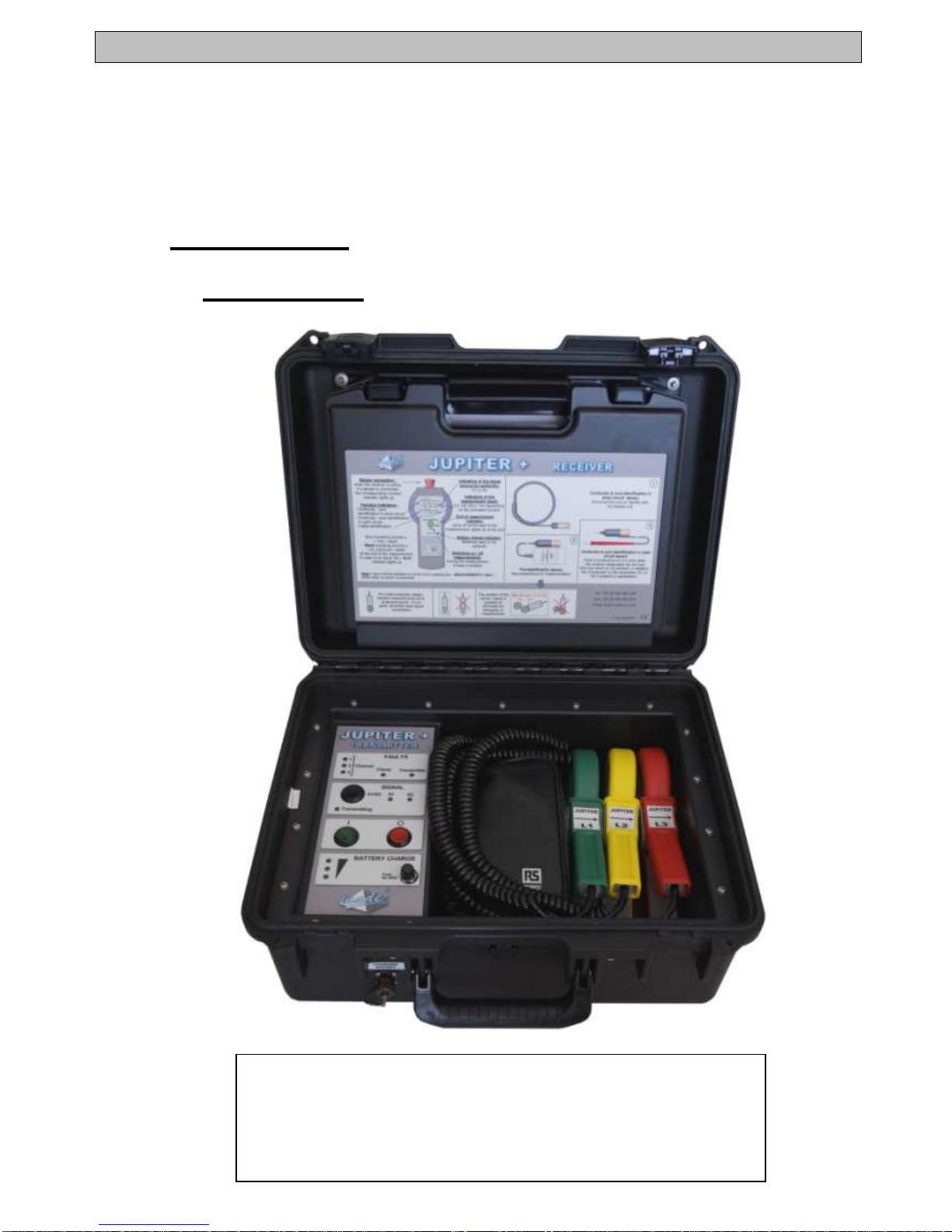
2. OVERVIEW ......................................................................................................................7
2.1. Working Principle ...........................................................................................................7
2.2. Composition....................................................................................................................8
2.2.1. Transmitter......................................................................................................................8
2.2.2. Receiver...........................................................................................................................9
2.2.2.1. Standard Sensors......................................................................................................10
2.2.2.2. Optional Sensor.........................................................................................................11
3. IMPLEMENTATION........................................................................................................12
3.1. JUPITER+ TRANSMITER..............................................................................................12
3.1.1. Overview of the Transmitter.........................................................................................13
3.1.2. Transmitter general functioning..................................................................................14
3.1.2.1. Power supply .............................................................................................................14
3.1.2.2. Transmitter functions................................................................................................15
3.1.2.3. Transmitter connection.............................................................................................15
3.1.3. Precautions for using the transmitter.........................................................................16
3.2. JUPITER+ RECEIVER ...................................................................................................17
3.2.1. Use of receiver..............................................................................................................20
3.2.1.1. Pre-identification mode.............................................................................................21
3.2.1.2. Core identification in open circuit and continuity to S1 Transmitter mode .........22
3.2.1.3. Core identification and continuity in short circuit mode .......................................23
3.2.1.4. Location in short circuit for 4 drivers of identical section mode (option)............24
3.2.2. Batteries ........................................................................................................................25
4. TECHNICAL CARACTERISTICS...................................................................................26
5. MAINTENANCE AND GUARANTEE.............................................................................27
5.1. Reminder .......................................................................................................................27
5.2. Recycling.......................................................................................................................27
5.3. Guarantee......................................................................................................................27
5.3.1. Limitation.......................................................................................................................28
5.3.2. Claims limitations.........................................................................................................29

4 / 30
5.4. Copyright.......................................................................................................................29
6. ANNEXE.........................................................................................................................30
6.1. CE conformity declaration ...........................................................................................30

SAFETY INFORMATION
5 / 30
This document establishes the user guide of the JUPITER +. It
describes the implementation of the device, as well as the various
ways of functioning to facilitate his use.
1.SAFETY INFORMATION
1.1.Safety advice
Please read this manual carefully before unpacking, configuring or
using this equipment. Note all indications of danger and other
warnings. The failure to observe these recommendations could result
in serious injury to the operator or could damage the equipment. To
ensure that the protection provided by this equipment is appropriate,
do not use or install it other than in accordance with the conditions
indicated in this manual.
Do not dismantle the cases. This operation is limited exclusively to
personnel qualified by MADE.
1.2.Use of safety instructions
DANGER: Indicates a situation eminently or potentially dangerous
that, if not avoided, would cause serious or deadly injuries.
ATTENTION: Indicates a potentially dangerous situation that could
cause superficial or moderate injuries.
Remark: Information that merits attention

SAFETY INFORMATION
6 / 30
1.3.Warming Labels
Read all labels and wording affixed to the instrument. Bodily injuries or
equipment damage could occur if these instructions are not respected.
Symbol requiring reference
to the instruction manual for
instructions concerning
operation or safety
recommendations.
Class I –Earthing mandatory
IP Std. –Degree of protection
IK Std. –Degree of protection
IK 07
IP 21

OVERVIEW
7 / 30
2.OVERVIEW
2.1.Working Principle
Identification of cables in a trench, gutter and in cable shelf.
With short-circuited ends
Identifying the phases and checking cable continuity to
transmitter S1
With short-circuited ends (closed circuit)
With open-circuit ends.
The configuration required for each of these modes is described in
this document.
Each of the functions is usually carried out on unpowered MV & LV
cables (customer loads on-line).
The signals and the physical principles used are common for each
function.
The JUPITER system is made up of a Transmitter and a Receiver.
The Transmitter is in a shock-proof carrying case which also
contains the various accesories. The connector for the current
injection clamps is on the front face of the Transmitter.
The Receiver is in a soft carrying case which fits into the Transmitter
case. This also contains the 3 sensors used for cable and
conductor/phase identification:
Cable identification
Continuity and core identification in open circuit.
Continuity and core identification in short circuit
Co
rdo
n
ch
arg
eur
réc
ept
eur

OVERVIEW
8 / 30
Option :
•Core identification in short circuit adapted for LV 4 conductor
cables, with visually unidentifiable neutral
2.2.Composition
2.2.1.Transmitter
3 current clamps with their connecting cable*
220V~ supply cable
1 Short-Circuiting cable

OVERVIEW
9 / 30
2.2.2.Receiver

OVERVIEW
10 / 30
2.2.2.1.Standard Sensors
•Sensor for « Core identification, short-circuited ends » :
•
•Sensor for « Core identification, open circuit ends » :
•Sensor for identification :

OVERVIEW
11 / 30
2.2.2.2.Optional Sensor
•Sensor for core identification, short-circuited ends, adapted
for LV 4 conductor cables, with unidentifiable neutral
visually.
•

IMPLEMENTATION
12 / 30
3.IMPLEMENTATION
3.1.JUPITER+ TRANSMITER
From turn-on by the operator, the Transmitter is activated and
generates the frequency signals necessary for identifying unpowered
MV & LV cables.
It is possible to turn the JUPITER+ Transmitter on S2 mode (with
different frequencies) for a utilization with two Transmitters at the
same time at the ends of a cable, one in S1 mode and the second on
S2 mode.
The type of utilization allows cores identification in open circuit once
the cable is cut at both ends without moving the Transmitter (useful
operation with replacing a joint or example).This Transmitter allows
only an utilization in S1 mode, or S2 mode with another Transmitter in
S1 mode.
Only one JUPITER+ Transmitter in S2 mode does not
allow core identification in open and short circuit
function!
The possible operations are :
•Identification of cables (Short-circuited ends)
•Continuity and identifying the cores with open circuit ends
(after cutting the cable)
•Identifying the cores with short circuited.
Once the Transmitter is started, no further action by the operator
is necessary to activate the functions described below.
When turned-on, the Transmitter is on S1 mode. A press on S1/S2
button activates S2 mode. Another press turn the Transmitter back to
S1 mode.

IMPLEMENTATION
13 / 30
These functions are possible on an unpowered MV or LV network and
for all types of cables:
HN, Paper, PE.
When used on an LV network, it is not necessary to disconnect
the customer loads.
3.1.1.Overview of the Transmitter
Fault indicator for the
injection circuits
Frequency set indicator
and Transmission indicator
Charge indicating lamps for
the batteries and protection
fuse
Current clamps
Short-circuit
Charger port
ON/OFF button

IMPLEMENTATION
14 / 30
3.1.2.Transmitter general functioning
3.1.2.1.Power supply
The JUPITER+ Transmitter runs on 7,2Ah 12V DC batteries.
When turned on, the charge level of the battery is indicated on the
front face.
The minimum autonomy of the transmitter is 8h.
The transmitter can run on internal batteries or during the charge when
using the external charger connected to the front connector closed to
the case handle.
The charger operates in three modes (RED –ORANGE –GREEN
LEDs):
•BOOST Mode, starts automatically on connecting the charger
to the mains if the battery is discharged. The current delivered
by the charger is then at maximum. The BOOST mode
enables the supply of up to 80% of the battery capacity and
can support the impact of loads due to transmission when the
Transmitter is active.
•ABSORPTION Mode,starts as soon as the battery voltage
has reached the maximum value of the BOOST. The current
then begins to reduce. The duration of the two phases
together (BOOST + ABSORPTION) will be a function of the
initial discharge state of the battery and whether the
Transmitter is activated or not. At the end of the absorption
phase, the battery is recharged to 95%.
•FLOATING Mode, at the finish of the two initial phases
(BOOST + ABSORPTION), the charger automatically
configures in FLOATING mode. The value of the current
delivered by the charger becomes asymptotic as it
approaches zero. This phase corresponds to holding the
batteries in charge (trickle current).

IMPLEMENTATION
15 / 30
The continuous use of this type of charger enables the long term
storage of the Transmitter, whilst maintaining the battery in optimum
charged condition (charger connected).
3.1.2.2.Transmitter functions
The JUPITER+ Transmitter consists of:
Three synthesized power generators
A monitoring unit for the internal components which :
Detects any faults in the transmission circuits (over-
currents or low currents) and indicates which clamp is
concerned.
Monitors the discharge level of the battery –the
transmission is automatically stopped if the battery
reaches a discharge level that could affect its life time.
A front face –instrument panel with 4 different zones:
Faults zone
S1 or S2 signal selection button
ON/OFF button
Battery zone : Battery charge indicator and protection
fuse
An external plug for charging the battery
3.1.2.3.Transmitter connection
The transmitter is connected on the near end of the cables
using the current clamps on the connection case. Both cable
ends are short-circuited and can be earthed (Do not include
the cable screen).
Ensure that both cable ends are short-circuited, using the
appropriate connection wires.
Turn on the transmitter.

IMPLEMENTATION
16 / 30
It is better to place the current clamps before starting the transmitter.
If not, opening the clamps during transmitter causes the clamp fault
lights to illuminate.
L1 L2 L3 L1 L2 L3
L1 L2 L3 N N L1 L2 L3
HTA
BT 4 conducteurs
3.1.3.Precautions for using the transmitter
THE CURRENT CLAMPS MUST ALL HAVE THE SAME
ORIENTATION WITH RELATION TO THE CABLE END (Indicated
by the arrows on the clamps).
CHECK THAT THE CLAMPS ARE ON AN UNSCREENED LENGTH
OF CABLE. IF NECESSARY, USE WOODEN CLAMPS OR TAPE TO
HOLD THEM IN POSITION.
TO AVOID RISK OF ERROR IN CABLE DESIGNATION, USE ONLY
ONE JUPITER+ TRANSMITTER ON A SITE.
AFTER TURN-ON, CHECK ON THE FRONT FACE:
THAT THERE ARE NO TRANSMISSION CIRCUIT FAULTS
THE BATTERY CHARGE LEVEL

IMPLEMENTATION
17 / 30
3.2.JUPITER+ RECEIVER
The JUPITER+ Receiver assembly consists of:
The Receiver to which are connected the sensors
Inductive sensor for identification
Probes for core identification and continuity with open
circuit.
Flexible Identifying loops for short-circuited core
identification
On option: a double flexible loop for core identification on a
4 conductor LV cable.
The Receiver and its sensors are supplied in a carrying case, which
itself fits into the lid of the Transmitter case.
The JUPITER+ Receiver is used to identify a cable of which the
extremities are in short-circuit and earthed, to identify the cores in an
open or closed circuit cable.
This is done in normal operation on unpowered HV & LV networks.
Nevertheless, as previously mentioned, the receiver and the Rogowski
coil may be used in live LV conditions (see page 11).
The JUPITER+ Receiver is equipped with sensors dedicated to each
function to « extract » the signals emitted by the JUPITER+
Transmitter.
The results obtained, by the Receiver, require no interpretation, the
detection algorithms assure safety.

IMPLEMENTATION
18 / 30
Receiver with its various sensors

IMPLEMENTATION
19 / 30
Socket for sensor
connection
Indication of the transmitter
source of the signal
Measurement display in
core identification mode
Measurement display in
identification and
continuity mode
End of measurement
indicator
On and measurement
initiation button
Battery fault indication

IMPLEMENTATION
20 / 30
3.2.1.Use of receiver
Connecting a sensor to the Receiver automatically sets the operating
mode which is indicated by a LED.
These modes are:
•Continuity and Identification in short-circuit
•Continuity and Identification in open-circuit
•Pré-identification
One press of the « Measurements » button turns on and illuminates
the LED corresponding to the mode selected by the chosen sensor,
which confirms to the operator the type of measurement to carry out.
After 30 seconds with no press of the « Measurements » button, the
Receiver switches off until a new button press.
If there is no sensor connected, one press on « Measurements »
button illuminates during 1 second all LEDs to be sure they are all
operational.
Certain modes are only available when the Transmitter is in S1 mode
or when two Transmitters, one in S1 mode and the second on S2
mode are connected to the ends of the same cable. A transmitter in S2
mode only does not allow core identification in open-circuit or short-
circuit. This kind of utilization automatically appears when two
transmitters in S1 and S2 mode are connected to the same cable and
that this cable is cut after pre-identification.
Table of contents