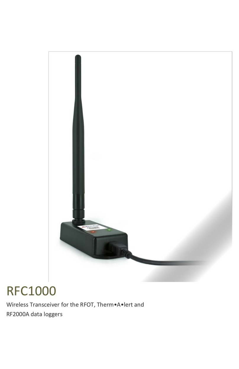
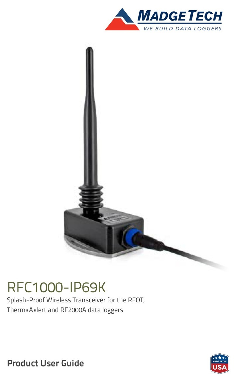
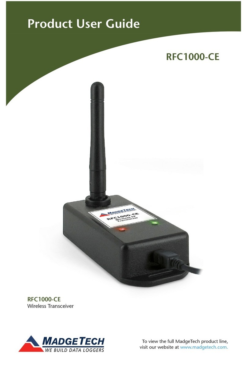
MadgeTech RFC1000-CE User manual

Specifications subject to change.
See MadgeTech’s terms and conditions at www.madgetech.com
Interface Type USB (to PC) / Wireless (to Data Logger)
Operating Environment -20 to +85°C, 0 to 95%RH non-condensing
LED Indicators Red & Green
Enclosure Materials ABS Plastic (body), PVC Plastic (antenna)
Dimensions Enclosure: 3.8” x 1.6” x 0.8” / Antenna: 2.7”
Weight 1.4oz (40g)
Compatible
Data Loggers:
RFOT, Therm•A•lert, Therm•A•lert-P,
Therm•A•lert-RH, Therm•A•lert-GB, RF2000A Series
Approvals FCC ID: OA3MRF24J40MC, IC#: 7693A-24J40MC, CE,
ETSI 300 328 (EU R&TTE)
Transmission Distance
(To other RFC1000-CE’s)
2,500’ max. outdoors - line of sight unobstructed
700’ max. indoors - typical urban environment
Transmission Distance
(To data loggers)
2,000’ max. outdoors - line of sight unobstructed
500’ max. indoors - typical urban
Maximum number of
connected data loggers 64
Sensitivity: -95dBm Typical
Frequency 2.405GHz - 2.475GHz
Ingress Protection IP40
RFC1000-CE
Wireless Transceiver
RFC1000-CE
.
Product User Guide
Distributor: LoggerShop Technologies | Dorset

Product User Guide RFC1000-CE
5
Compliance Information
• “This device complies with Part 15 of the FCC Rules. Operation is subject to the
following two conditions: (1) this device may not cause harmful interference, and
(2) this device must accept any interference received, including interference that
may cause undesired operation.”
• “To satisfy FCC RF Exposure requirements for mobile and base station
transmission devices, a separation distance of 20cm or more should be
maintained between the antenna of this device and persons during operation. To
ensure compliance, operation at closer than this distance is not recommended.
The antenna(s) used for this transmitter must not be co-located or operating in
conjunction with any other antenna or transmitter.”
• “This device complies with Industry Canada license-exempt RSS standard(s).
Operation is subject to the following two conditions: (1) this device may not
cause interference, and (2) this device must accept any interference, including
interference that may cause undesired operation of the device.
Le présent appareil est conforme aux CNR d’Industrie Canada applicables
aux appareils radio exempts de licence. L’exploitation est autorisée aux deux
conditions suivantes: (1) l’appareil ne doit pas produire de brouillage, et (2)
l’utilisateur de l’appareil doit accepter tout brouillage radioélectrique subi, même
si le brouillage est susceptible d’en compromettre le fonctionnement.”
• “Under Industry Canada regulations, this radio transmitter may only operate
using an antenna of a type and maximum (or lesser) gain approved for the
transmitter by Industry Canada. To reduce potential radio interference to other
users, the antenna type and its gain should be so chosen that the equivalent
isotropically radiated power (e.i.r.p.) is not more than that necessary for
successful communication.
Conformément à la réglementation d’Industrie Canada, le présent émetteur
radio peut fonctionner avec une antenne d’un type et d’un gain maximal (ou
inférieur) approuvé pour l’émetteur par Industrie Canada. Dans le but de réduire
les risques de brouillage radioélectrique à l’intention des autres utilisateurs, il faut
choisir le type d’antenne et son gain de sorte que la puissance isotrope rayonnée
équivalente (p.i.r.e.) ne dépasse pas l’intensité nécessaire à l’établissement d’une
communication satisfaisante.”
Distributor: LoggerShop Technologies | Dorset

Product User Guide
4
Mounting Instructions
For best wireless performance, both the RFC1000-CE and the MadgeTech Data
Loggers should be mounted in the same orientation. This usually means that
the external antenna should be pointing straight up. The antenna can pivot to
accommodate either a wall mount or a desk mount.
RFC1000-CE
1
Product Notes
MadgeTech has designed an RFC1000-CE with a high powered transceiver that
has a substantially long transmission range, meaning better performance in
occluded environments (ovens, refrigerators, etc.). This RFC1000-CE also includes
an external antenna, allowing more flexibility with mounting positions in both
orientation and proximity to metal walls. This may be used as a repeater, or
directly plugged into the PC.
Transmission Distance
The RFC1000-CE transmits to other RFC1000-CEs up to 2500 feet maximum
typical outdoors/line of sight, 700 feet maximum typical indoors/urban.
The RFC1000-CE transmits to data loggers up to 2000 feet maximum
typical outdoors/line of sight, 500 feet maximum typical indoors/urban. The
RFC1000-CE can connect to a maximum of 64 data loggers. The RFC1000-CE
transmits on a frequency of 2.405GHz - 2.475GHz.
Operating Environment
The RFC1000-CE is rated for use in an environment with temperatures from
-20°C to 85°C and a humidity range of 0% to 95% RH non-condensing. The
RFC1000-CE is rated IP40 and is protected against solids that are greater than
1mm in size. This device is not water resistant.
LEDs
The red LED indicates that the device has power. The green LED will blink when
communicating with other MadgeTech devices.
Installation Guide
Installing the Software
Insert the MadgeTech 4 Software Flash Drive into an open USB port on a
Windows PC. If the autorun does not appear, locate the drive on the computer
and double click on Autorun.exe. Install the MadgeTech Software and USB
Interface Drivers (under Drivers and Third Party Tools).The software can also
be downloaded from www.madgetech.com.
Channel Programming
The RFC1000-CE transmits data on the 2.4GHz band, channel 11. Each
MadgeTech Wireless Data Logger and RFC1000-CE has a set of dip switches with
which the channel may be programmed.
Any MadgeTech Data Logger or RFC1000-CE that is on the same network is
required to use the same channel. If they are not on the same channel, the
devices will not communicate with one another.
Distributor: LoggerShop Technologies | Dorset

Product User Guide
2
RFOT: To program the channel on an RFOT data logger, unscrew the body of
the RFOT and remove the enclosure. Switch the wireless ON / OFF switch (red
switch, next to the probe cable connector) to ‘0’. The dip switches are located
on the back of the PCB (opposite side of the battery). Change the dip switches to
match the desired channel settings. Return the wireless ON / OFF switch to ‘1’.
Therm-A-Lert Series: Switch the wireless ON / OFF switch to ‘0’. The dip
switches are located on the back of the device. Switch the wireless ON / OFF
switch back to ‘1’.
Wireless 2000A Series: Connect the device to the PC using the USB cable
(supplied). Highlight the device from the Connected Devices box in the software.
Select Properties and then choose the Wireless tab. Click on the drop down box
and select the desired channel. Click Apply and then Yes to apply the settings.
Click OK to close the box.
On the key pad of the data logger, press any key to activate the display. Press and
hold the Wireless button until the Wireless option reads on.
Deploying and Activating Devices
Step 1: Plug the RFC1000-CE into the USB port on the base station computer.
(Additional RFC1000-CEs can be used as repeaters to transmit over greater distances)
Step 2: If using multiple RFC1000-CEs plug each one into a wall outlet in the
desired locations. (If transmitting over a distance greater than 700 feet indoors or
2500 feet outdoors or there are walls/obstacles/corners that need to be maneuvered
around, set up additional RFC1000-CEs as needed.)
Step 3: Verify that the data loggers are in wireless transmission mode. (See
Channel Programming steps above)
Step 4: On a Windows PC, launch the MadgeTech 4 software program. All
active data loggers will be listed in the software showing that the device(s) are
recognized.
Step 5: To activate the data loggers, click on one to highlight, then click
the Claim icon, and then click the Start button. Repeat this step to activate
additional listed data loggers.
RFC1000-CE
3
The default wireless channel for MadgeTech wireless devices is channel 11.
Different wireless channels may be used to create multiple networks in one
area, or to avoid wireless interference from other devices. The diagram below
show the orientations available of the switches for each channel. Channel 26 (all
switches in the up position) is not supported.
Channel 11 Channel 12 Channel 13 Channel 14
Channel 15 Channel 16 Channel 17 Channel 18
Channel 19 Channel 20 Channel 21 Channel 22
Channel 23 Channel 24 Channel 25 Channel 26
(not supported)
Follow the instructions below to configure the channel settings for MadgeTech
Data Loggers.
RFC1000-CE: To program the channel on an RFC1000-CE, first unplug the
RFC1000-CE. Use a Phillips head screwdriver to unscrew the enclosure. The
dip switches are located on the front of the PCB circuit board. Change the dip
switches to match the desired channel settings by referring to the diagram above.
Reconnect the RFC1000-CE.
Distributor: LoggerShop Technologies | Dorset
Other manuals for RFC1000-CE
2
Table of contents
Other MadgeTech Transceiver manuals
Popular Transceiver manuals by other brands

Microwave Data Systems
Microwave Data Systems MDS 4310 Installation, Operation & Field Maintenance

Alinco
Alinco DJ-V17TFH instruction manual

NORCAL
NORCAL NC2030 manual

Standard Horizon
Standard Horizon QUANTUM GX5500S owner's manual

Fiberplex
Fiberplex SFP-BHDVXC-0000-R user manual

Standard Horizon
Standard Horizon MATRIX Series owner's manual