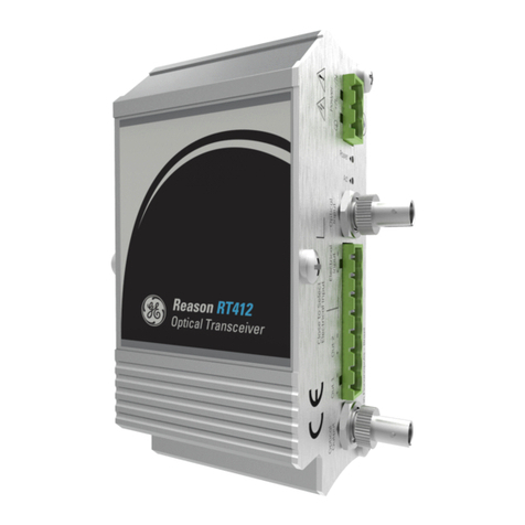
GE Reason RT411 User manual

GE
Grid Solutions
Reason RT411
Time Signal Distributor
Technical Manual
Platform Hardware Version: A
Publication Reference: RT411-TM-EN-HWA-3v3
imagination at work


Contents
Table of Figures 5
List of Tables 6
Chapter 1: Introduction 7
1Foreword 7
Target Audience 7
Acronyms and abbreviations 7
2Product Scope 9
3Functional Overview 9
4Standards Compliance 9
Chapter 2: Safety Information 11
1Health and Safety 11
2Symbols 11
3Installation, Commissioning and Servicing 12
Lifting Hazards 12
Electrical Hazards 12
Fusing Requirements 14
Equipment Connections 14
Pre-energization Checklist 15
Peripheral Circuitry 16
Upgrading/Servicing 16
4Decommissioning and Disposal 17
Chapter 3: Hardware Design 18
1Equipment View 18
2Power Supply 18
Chapter 4: Installation 20
1Unpacking 20
Normal Use of the Equipment 20
2Mounting 20
Connectors 21
Power Supply 21
Grounding (Earthing) 22
Electrical/Optical Time Input 23
Selecting the Type of Time Input 23
Optical Outputs 24
Electrical Outputs 24
3Powering Up 25
4Preventive Maintenance Actions 25
Preventive Actions 25
Chapter 5: Maintenance 27

1Power Indicator Off 27
2Act Indicator Off 27
3Cleaning Instructions 27
4Equipment Return 27
Chapter 6: Technical Specification 29
1Power Supply 29
2TTL Electrical Input 29
3Optical Input 30
4TTL Electrical Outputs 30
5Optical Outputs 31
6Environment 31
7Type Test 32
8Dimensions, Weight 35
Chapter 7: Ordering Options 36
1RT411 Cortec 36
Chapter 8: Appendixes 37
Appendix A –IRIG-B Standard Summary 37
Appendix B –Application Examples 42
Application Example 1: Traditional and Modern Time Sync 42
Application Example 2: System Wide Grandmaster Clock 42
Application Example 3: Synchrophasor, TWFL and Process Bus Applications 43
Application Example 4: IEEE 1588 in a PRP Network 44
Application Example 5: Time Sync Expansion using RT411 and RT412 45

Table of Figures
Figure 1: Functional Overview of RT411 9
Figure 2: Front view of RT411 18
Figure 3: View from RT411 connectors 18
Figure 4: Connectors of RT411 21
Figure 5: Pre-insulated tubular pin terminals 21
Figure 6: Supply connector assembly 22
Figure 7: RT411 power connection 22
Figure 8: RT411 Grounding Strap 23
Figure 9: Electrical/Optical Time Input 23
Figure 10: Input Selection 23
Figure 11: Optical Outputs 24
Figure 12: Electrical Outputs 24
Figure 13: Euro Type label for connections 25
Figure 14: RT411 Dimensions 35
Figure 15: Traditional x Modern Time Synchronization 42
Figure 16: System Wide Grandmaster Clock 43
Figure 17: Synchrophasor devices synced by RT430/434 43
Figure 18: TWFL application using RT430/434 for Time Sync 44
Figure 19: Process Bus application using PTP via the Station Bus network. 44
Figure 20: Process Bus application using PTP via the Station Bus network. 45
Figure 21: Time Sync expansion using RT411 and RT412 45

List of Tables
Table 1: RT411 connectors 21
Table 2: Jumper Selection of Time Input 24
Table 3: Power supply specifications 29
Table 4: TTL Electrical input specification 29
Table 5: Optical input specification 30
Table 6: TTL Electrical Outputs specification 30
Table 7: Optical Outputs specification 31
Table 8: Environment specification 31
Table 9: Enclosure Protection IEC 60529 31
Table 10: EMC tests were performed according to IEC 60255-26 referring to the
following standards 32
Table 11: Safety tests 33
Table 12: Environmental tests 34
Table 13: Dimensions and weight specification 35
Table 14: IRIG-B standard summary 37

Chapter 1 –Introduction
RT411
RT411
7
Reason RT411
Time Signal Distributor
Chapter 1: Introduction
This chapter provides general information about the technical manual and an
introduction to RT411 Time Signal Distributor.
1Foreword
This technical manual provides a functional and technical description of GE Reason
RT411 Time Signal Distributor, as well as a comprehensive set of instructions for using
the devices. The level at which this manual is written assumes that you are already
familiar with protection engineering and have experience in this discipline. The
description of principles and theory is limited to that which is necessary to understand
the product.
We have attempted to make this manual as accurate, comprehensive and user-friendly
as possible. However, we cannot guarantee that it is free from errors. Nor can we state
that it cannot be improved. We would therefore be very pleased to hear from you if you
discover any errors, or have any suggestions for improvement. Our policy is to provide
the information necessary to help you safely specify, engineer, install, commission,
maintain, and eventually dispose of this product. We consider that this manual provides
the necessary information, but if you consider that more details are needed, please
contact us.
GE Grid Solutions:
Worldwide Contact Center
Web: www.GEGridSolutions.com/contact
Phone: +44 (0) 1785 250 070
Target Audience
This manual is aimed towards all professionals charged with installing, commissioning,
maintaining, troubleshooting, or operating any of the products within the specified
product range. This includes installation and commissioning personnel as well as
engineers who will be responsible for operating the product.
The level at which this manual is written assumes that installation and commissioning
engineers have knowledge of handling electronic equipment. Also, system and
protection engineers have a thorough knowledge of protection systems and associated
equipment.
Acronyms and abbreviations
AC –Alternating Current;

RT411
Chapter 1 –Introduction
8
RT411
ACEB NEMEA - Acronyms and Abbreviations;
ASCII - American Standard Code for Information Interchange;
BMC - Best Master Clock;
BNC - Bayonet Neil Councilman connector;
Bps - Bytes per second;
bps - Bits per second;
CAT5 - Network Cable;
PLC - Programmable Logic Controller;
CMOS - Complementary Metal-Oxide-Semiconductor;
DB9 - Connector do type D-subminiature;
DC - Direct Current;
DCF77 - Time synchronization protocol Deutschland LORAN-C (Long Range Navigation -
C) Frankfurt 77 (77.5 kHz);
DMARK –Single pulse with a programmable date and time;
DNS - Domain Name System;
DST - Daylight Saving Time;
DTE - Data Terminal Equipment;
E2E - End-to-end;
ETH - Abbreviation of the term Ethernet;
FW - Abbreviation of the term Firmware;
GLONASS - GLObal NAvigation Satellite System from Russian Aerospace Defense Forces;
GND - Abbreviation of the term Ground;
GNSS - Global Navigation Satellite System;
GPS - Global Positioning System;
GPZDA - Serial Datagram format;
HTTP - Hypertext Transfer Protocol;
HTTPS - Hypertext Transfer Protocol Secure;
IEC - International Electrotechnical Commission;
IED - Intelligent Electronic Devices;
IEEE - Institute of Electric and Electronic Engineers;
HMI - Human-Machine Interface;
IP - Internet Protocol;
IP40 - Degree of protection 40;
IRIG-B - Time synchronization protocol Inter Range Instrumentation Group (Rate
Designation B);
LCD - Liquid Crystal Display;
MAC - Media Access Control;
MIB - Management Information Base;
NTP - Network Time Protocol;
OUT - Abbreviation of the term Output;
P2P - Peer-to-peer;
PLC - Programmable Logic Controller;
PPM - Pulse per minute;
PRP - Parallel Redundancy Protocol;
PPS - Pulse per Segundo;
PPX - Pulse per X s;
PTP - Precision Time Protocol;
RAIM - Receiver Autonomous Integrity Monitoring;
RJ45 - Ethernet Connector with 8 conductors;
RS232/485 - Serial port levels;
RX - Receiving data;
Chapter 1 –Introduction
RT411
RT411
9
SNMP - Simple Network Management Protocol;
SNTP - Simple Network Time Protocol;
ST - Bayonet-lock connector;
TCP - Transmission Control Protocol;
TMARK - Daily pulses with programmable time;
TTL - Transistor-to-Transistor logic;
TX - Data transmission;
UDP - User Datagram Protocol;
UTC - Universal Time Coordinate.
2Product Scope
RT411 - Time Signal Distributor expands the number of electrical/optical signal outputs
from a GPS/GNSS Clock. The equipment is ruggedized and specifically designed for
operation and to be part of the large scale electrical fixed installations, as electrical
power generation installations, electrical substations and electrical utilities control
systems.
RT411 multiplies IRIG-B demodulated, PPS or any signal with a voltage up to 5 Vdc, and
frequencies up to 5 MHz, through the electrical and optical outputs. The equipment’s
time accuracy is based on the accuracy of the time reference source been used.
The equipment has up to 10 electrical outputs with a 150 mA individual supply capacity
and up to 10 optical outputs for multimode fiber and ST connector.
It also has indicators for monitoring the received time reference signal and the power
supply.
3Functional Overview
Figure 1: Functional Overview of RT411
4Standards Compliance
The device has undergone a range of extensive testing and certification processes to
ensure and prove compatibility with all target markets.
Compliance with the European Commission Directive on EMC and LVD is demonstrated
using a Technical File.

RT411
Chapter 1 –Introduction
10
RT411
•EMC Compliance: Compliance with IEC 60255-26:2013 was used to establish
conformity.
•Product Safety: Compliance with IEC 61010-1:2010 was used to establish
conformity.
•Protective Class: Protective Class I. This equipment requires a protective
conductor (ground) to ensure user safety.
•Installation category: Compliance with IEC 61010-1:2010 Overvoltage Category II
•Environment: IEC 60068-2-1, IEC 60068-2-2, IEC 60068-2-30, IEC 60068-2-14, IEC
60255-21-1, IEC 60255-21-2. The equipment is intended for indoor use only. If it is
required for use in an outdoor environment, it must be mounted in a specific
cabinet or housing which will enable it to meet the requirements of IEC 60529
with the classification of degree of protection IP20.
•R&TTE Compliance: Radio and Telecommunications Terminal Equipment (R&TTE)
directive 99/5/EC. Conformity is demonstrated by compliance to both the EMC
directive and the Low Voltage directive, to zero volts.

Chapter 2 –Safety Information
RT411
11
RT411
Reason RT411
Time Signal Distributor
Chapter 2: Safety Information
This chapter provides information about the safe handling of the equipment. The
equipment must be properly installed and handled in order to maintain it in a safe
condition and to keep personnel safe at all times. You must be familiar with information
contained in this chapter before unpacking, installing, commissioning, or servicing the
equipment.
1Health and Safety
Personnel associated with the equipment must be familiar with the contents of this
Safety Information.
When electrical equipment is in operation, dangerous voltages are present in certain
parts of the equipment. Improper use of the equipment and failure to observe warning
notices will endanger personnel.
Only qualified personnel may work on or operate the equipment. Qualified personnel
are individuals who are:
•Familiar with the installation, commissioning, and operation of the equipment and
the system to which it is being connected.
•Familiar with accepted safety engineering practices and are authorized to energize
and de-energize equipment in the correct manner.
•Trained in the care and use of safety apparatus in accordance with safety
engineering practices
•Trained in emergency procedures (first aid).
The documentation provides instructions for installing, commissioning and operating
the equipment. It cannot, however cover all conceivable circumstances. In the event of
questions or problems, do not take any action without proper authorization. Please
contact your local sales office and request the necessary information.
Each product is subjected to routine production testing for Dielectric Strength and Protective
Bonding Continuity.
2Symbols
Throughout this manual you will come across the following symbols. You will also see
these symbols on parts of the equipment.

RT411
Chapter 2 –Safety Information
RT411
12
Caution: Refer to equipment documentation. Failure to do so could
result in damage to the equipment
Risk of electric shock
Ground terminal. Note: This symbol may also be used for a
protective conductor (ground) terminal if that terminal is part of a
terminal block or sub-assembly.
Protective conductor (ground) terminal
Both direct and alternating current
Instructions on disposal requirements
The term 'Ground' used in this manual is the direct equivalent of the European term
'Earth'.
3Installation, Commissioning and Servicing
Lifting Hazards
Many injuries are caused by:
•Lifting heavy objects
•Lifting incorrectly
•Pushing or pulling heavy objects
•Using the same muscles repetitively
Plan carefully, identify any possible hazards and determine how best to move the
product. Look at other ways of moving the load to avoid manual handling. Use the
correct lifting techniques and Personal Protective Equipment (PPE) to reduce the risk of
injury.
Electrical Hazards
All personnel involved in installing, commissioning, or servicing this
equipment must be familiar with the correct working procedures.

Chapter 2 –Safety Information
RT411
13
RT411
Consult the equipment documentation before installing,
commissioning, or servicing the equipment.
Always use the equipment as specified. Failure to do so will
jeopardize the protection provided by the equipment.
Removal of equipment panels or covers may expose
hazardous live parts. Do not touch until the electrical
power is removed. Take care when there is unlocked
access to the rear of the equipment.
Isolate the equipment before working on the terminal
strips.
Use a suitable protective barrier for areas with
restricted space, where there is a risk of electric shock
due to exposed terminals.
Disconnect power before disassembling. Disassembly of the
equipment may expose sensitive electronic circuitry. Take suitable
precautions against electrostatic voltage discharge (ESD) to avoid
damage to the equipment.
NEVER look into optical fibers or optical output connections. Always
use optical power meters to determine operation or signal level.
Testing may leave capacitors charged to dangerous voltage levels.
Discharge capacitors by reducing test voltages to zero before
disconnecting test leads.
If the equipment is used in a manner not specified by the
manufacturer, the protection provided by the equipment may be
impaired.
Operate the equipment within the specified electrical and
environmental limits.
Before cleaning the equipment, ensure that no connections are
energized. Use a lint free cloth dampened with clean water.
Integration of the equipment into systems shall not interfere with its
normal functioning.
The functioning of the device has been certified under the
circumstances described by the standards mentioned. Usage of the
equipment in different conditions from the specified in this manual
might affect negatively its normal integrity.

RT411
Chapter 2 –Safety Information
RT411
14
The equipment shall have all their rear connectors attached even if
they are not being used, in order to keep their levels of ingress
protection as high as possible
Never manipulate liquid containers near the equipment even when it
is powered off.
Avoid modification to the wiring of panel when the system is running.
Fusing Requirements
A high rupture capacity (HRC) fuse type with a maximum current rating
of 10 Amps and a minimum dc rating of 250 V dc may be used for the
auxiliary supply (for example Red Spot type NIT or TIA). Alternatively,
a miniature circuit breaker (MCB) of type C, 10 A rating, compliant
with IEC 60947-2 may be used.
Reason devices contain an internal fuse for the power supply, which is
only accessed by opening the product. This does not remove the
requirement for external fusing or use of an MCB as previously
mentioned. The ratings of the internal fuses are 2 Amp, type T, 250V.
Equipment Connections
Terminals exposed during installation, commissioning
and maintenance may present a hazardous voltage
unless the equipment is electrically isolated.
Tighten M3 clamping screws of heavy-duty terminal block connectors
to a nominal torque of 1.0Nm. Tighten captive screws of header-type
(Euro) terminal blocks to 0.5 Nm minimum and 0.6 Nm maximum.
Always use insulated crimp terminations for voltage and current
connections.
Always use the correct crimp terminal and tool according to the wire
size.
In order to maintain the equipment’s requirements for protection
against electric shock, other devices connected to the equipment shall
have protective class equal or superior to Class I.

Chapter 2 –Safety Information
RT411
15
RT411
Ground the equipment with the supplied PCT (Protective Conductor
Terminal).
Do not remove the PCT.
The PCT is sometimes used to terminate cable screens. Always check
the PCT’s integrity after adding or removing such ground connections.
The user is responsible for ensuring the integrity of any protective
conductor connections before carrying out any other actions.
The PCT connection must have low-inductance and be as short as
possible. For best EMC performance, ground the unit using a 10 mm
(0.4 inch) wide braided grounding strap.
All connections to the equipment must have a defined potential.
Connections that are pre-wired, but not used, should be grounded, or
connected to a common grouped potential.
Pay extra attention to diagrams before wiring the equipment. Always
be sure that the connections are correct before energizing the
circuits.
Pre-energization Checklist
Check voltage rating/polarity (rating label/equipment documentation).
Check protective fuse or miniature circuit breaker (MCB) rating.
Check integrity of the PCT connection.

RT411
Chapter 2 –Safety Information
RT411
16
Check voltage and current rating of external wiring, ensuring it is
appropriate for the application.
Peripheral Circuitry
Where external components such as resistors or voltage dependent
resistors (VDRs) are used, these may present a risk of electric shock or
burns if touched.
Operation of equipment connected to RT41x under environmental
conditions such as temperature and humidity that exceed the
conditions specified in their respective manuals can cause
malfunctioning or even irreversible damage to them or the nearby
installation.
There might be situations in which the unit is operating within its
environmental operational range, but the computers, equipment
connected to them or nearby equipment are operating outside their
operational range. That situation can cause malfunctioning and/or
irreversible damage to those devices. In that occasion the
communication to the Reason equipment might be compromised but
its operational and safety capacities will not be affected.
Upgrading/Servicing
Do not insert or withdraw modules, PCBs or expansion
boards from the equipment while energized, as this
may result in damage to the equipment. Hazardous
live voltages would also be exposed, endangering
personnel.
Internal modules and assemblies may have sharp edges. Take care
when inserting or removing modules into or out of the IED.

Chapter 2 –Safety Information
RT411
17
RT411
4Decommissioning and Disposal
Before decommissioning, completely isolate the equipment power
supply (both poles of any dc supply). The auxiliary supply input may
have capacitors in parallel, which may still be charged. To avoid
electric shock, discharge the capacitors using the external terminals
before decommissioning.
Avoid incineration or disposal to water courses. Dispose of the
equipment in a safe, responsible and environmentally friendly manner,
and if applicable, in accordance with country-specific regulations.

RT411
Chapter 3 –Hardware Design
18
RT411
Reason RT411
Time Signal Distributor
Chapter 3: Hardware Design
This chapter demonstrates the main hardware characteristics from RT411
1Equipment View
The front panel of the RT411 comprises two indicators. The Act indicator shows if the
time reference is detected, and the Power indicator simply shows if the equipment is
energized or not.
Figure 2: Front view of RT411
Figure 3: View from RT411 connectors
The RT411 comprises:
•One power supply, AC/DC high voltage or DC low voltage;
•One electrical input, one optical input and one input selection connection for time
reference;
•Ten TTL electrical outputs for synchronization, been 8x using the Euro Type
connector and 2x the BNC connectors;
•Ten optical outputs using ST connectors;
2Power Supply
The power supply can have the nominal voltage ranges listed below:
1. 100-240Vac, 110-250Vdc;
2. 24-48Vdc.


RT411
Chapter 4 –Installation
20
RT411
Reason RT411
Time Signal Distributor
Chapter 4: Installation
The RT411 is ruggedized and specifically designed for operation and to be part of the
large scale electrical fixed installations, as electrical power generation installations,
electrical substations and electrical utilities control systems.
1Unpacking
Unpack the unit carefully and make sure all the accessories and cables are put aside so
they will not be lost.
Check the contents against the packing list that goes with the product. If any of the
content listed is missing, please contact GE Grid Solutions (see contact information in
Maintenance chapter).
Examine the unit for any shipping damage. If the unit is damaged or fails to operate,
notify the shipping company without delay. Only the consignee (the person or company
receiving the unity) can file a claim against the carrier for shipping damage.
We recommend you to keep the original packing materials for possible transport in the
future.
Normal Use of the Equipment
In order to maintain the equipment integrity, levels of protection and assure user
safety, the RT411 must be installed in an enclosed panel with recommended ingress
protection rating of IP54 or above.
The enclosing panel must ensure that the equipment is unexposed and protected
against impact and water, whilst maintaining adequate temperature and humidity
condition for the devices. Furthermore, the equipment must have all their connectors
attached, even if not being used, to keep their levels of ingress protection as high as
possible.
2Mounting
The equipment has been designed to be mounted in a standard 19-inch rack using four
M6x15 screws.
Keep adequate clearance for all connections. In particular, the optical fiber cables
should be installed in compliance with the 30 mm minimum bending radius.
Table of contents
Other GE Transceiver manuals

GE
GE MDS 9710T User manual

GE
GE MDS SD Series User manual

GE
GE MDS TransNEXT User manual

GE
GE MDS SD Series User manual

GE
GE A3-5825B User manual

GE
GE MDS NETio-TB Series Original operating instructions

GE
GE Reason RT412 User manual

GE
GE MDS SD4A User manual

GE
GE MDS Mercury Series User manual

GE
GE MDS Mercury Series User manual

GE
GE MDS Mercury Series User manual

GE
GE MDS SD Series User manual

GE
GE 3-5875A User manual

GE
GE MDS SDM9 User manual

GE
GE MDS SD Series User manual

GE
GE MDS SD 1 User manual

GE
GE MDS SD4 Series User guide

GE
GE GEC-1PVTC-F Assembly instructions

GE
GE CITIZENS BAND TRANSCEIVER 3-5980 User manual

GE
GE MDS Mercury Series User manual