Madrigal Audio Mark Levinson ?20.6 User manual

17
Operating Manual
Mark Levinson®
Nº20.6
Monaural Reference Amplifier
Madrigal Audio Laboratories, Inc.

19
Important safety instructions
Read all instructions and precautions carefully and completely before operating your Nº20.6
Monaural Reference Amplifier.
1. ALWAYS disconnect your entire system from the AC mains before connecting or disconnecting
any cables, or when cleaning any component.
2. This product is equipped with a three-conductor AC mains power cord which includes an earth
ground connection. To prevent shock hazard, all three connections must ALWAYS be used. If
your electrical outlets will not accept this type of plug, an adapter may be purchased. If an
adapter is necessary, be sure it is an approved type and is used properly, supplying an earth
ground. If you are not sure of the integrity of your home electrical system, contact a licensed
electrician for assistance.
3. AC extension cords are not recommended for use with this product. If an extension cord must
be used, be sure it is an approved type and has sufficient current-carrying capacity to power
this product.
4. NEVER use flammable or combustible chemicals for cleaning audio components.
5. NEVER operate this product with any covers removed.
6. NEVER wet the inside of this product with any liquid.
7. NEVER pour or spill liquids directly onto this unit.
8. NEVER block air flow through ventilation slots or heatsinks.
9. NEVER bypass any fuse.
10. NEVER replace any fuse with a value or type other than those specified.
11. NEVER attempt to repair this product. If a problem occurs, contact your Mark Levinson®dealer.
12. NEVER expose this product to extremely high or low temperatures.
13. NEVER operate this product in an explosive atmosphere.
14. ALWAYS keep electrical equipment out of the reach of children.

20
Thank you for choosing the Mark Levinson
®
Nº20.6 Monaural Reference Amplifier.
A great deal of effort went into the design and construction of this precision device. Used properly, it
will give you many years of enjoyment.

21
Table of contents
Unpacking and placement .......................................................................1
Unpacking .............................................................................................. 1
Placement ............................................................................................. 1
Ventilation .............................................................................................. 1
Custom installations .............................................................................. 1
Voltage selection ........................................................................................2
Figure 1: Rear panel .......................................................................
2
Signal connection .......................................................................................3
Connectors ............................................................................................ 3
Cables .................................................................................................... 3
Connection methods and operating modes .................................... 3
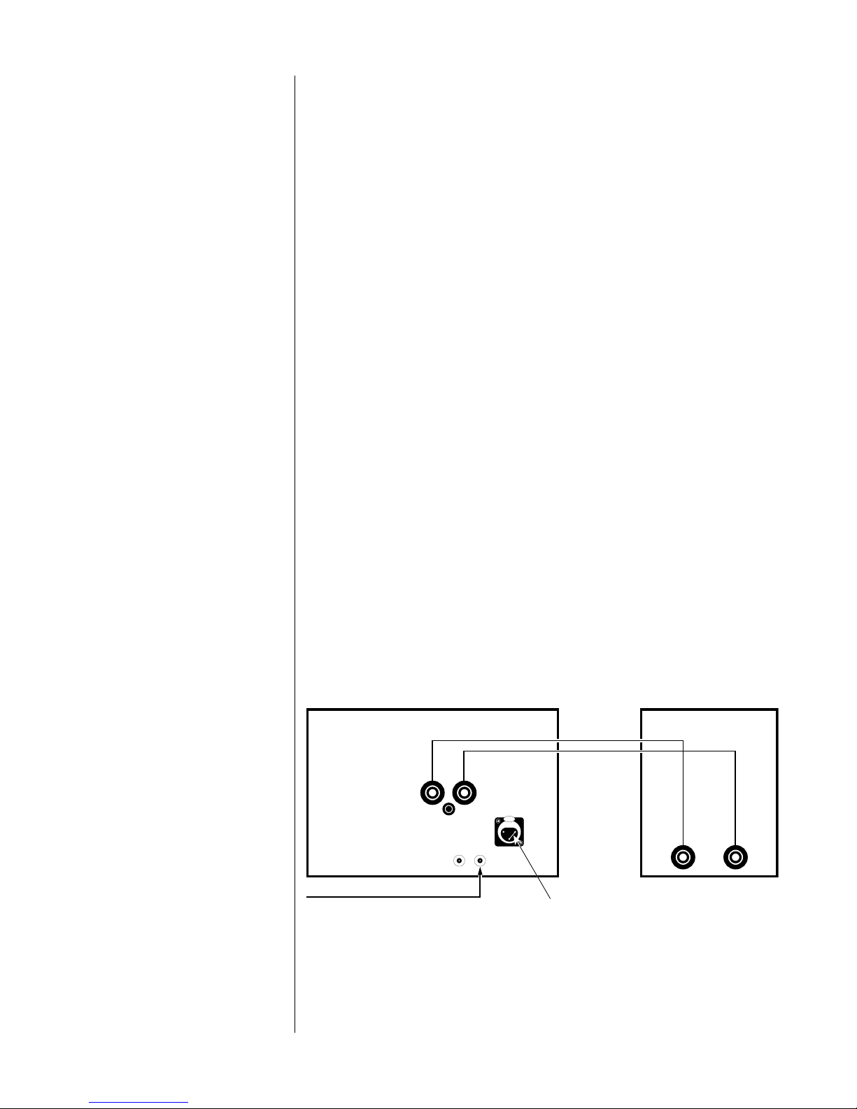
Single-ended normal (non-inverting) operation ............................... 3
Figure 2: Connections for single-ended normal (non-inverting)
operation ..................................................................................
3
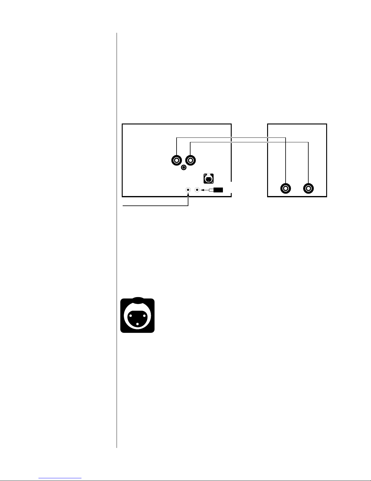
Single-ended inverting operation ....................................................... 4
Figure 3: Connections for single-ended inverting operation .....
4
Balanced normal (non-inverting) operation...................................... 4
Figure 4: Female input connector ................................................
4
Figure 5: Connections for balanced normal (non-inverting)
operation ..................................................................................
5
Speaker connections .................................................................................6
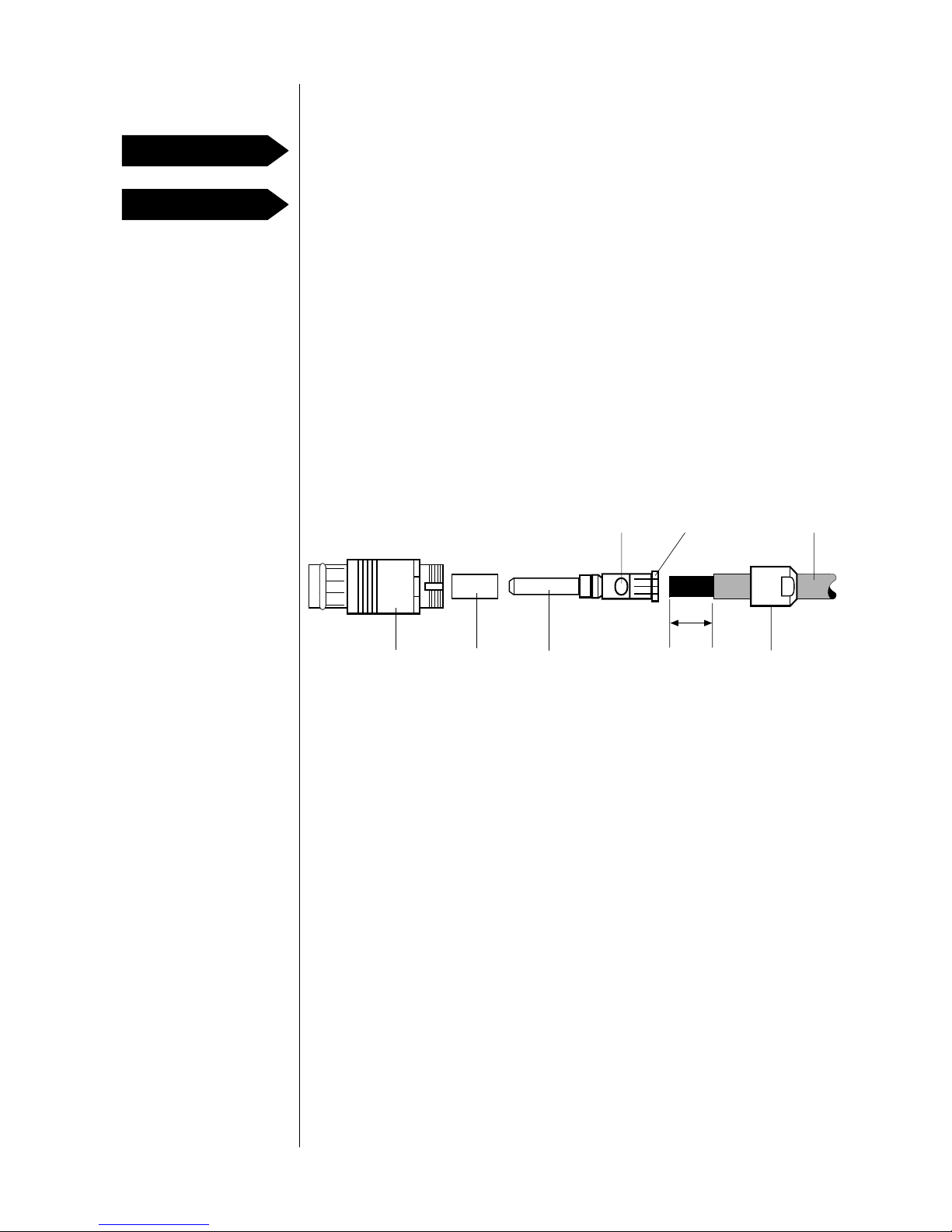
Assembling the speaker connectors .................................................. 6
Figure 6: Line-mount speaker connector assembly....................
6
Connecting the speakers ..................................................................... 7
Chassis ground ...................................................................................... 7
Power connection .......................................................................................8
Connecting the AC power cord ......................................................... 8
Figure 7: AC power cord polarity .................................................
8
Performance tips ................................................................................... 8
Protection circuitry ................................................................................ 8
Bridged operation .......................................................................................9
Connections for balanced bridged operation ................................. 9
Figure 8: Connections for balanced bridged operation ...........
9
Figure 9: Balanced bridging cable .............................................
10
Connections for single-ended bridged operation .......................... 10
Figure 10: Connections for single-ended bridged operation..
11
Care and Maintenance............................................................................12
Cleaning ............................................................................................... 12
Fuses...................................................................................................... 12
Specifications ............................................................................................13
Dimensions.................................................................................................14
Figure 11A: Dimensions, Nº20.6, top view ..................................
14
Figure 11B: Dimensions, Nº20.6, side view ..................................
14

1
Unpacking and placement
Unpack your Nº20.6 Monaural Reference Amplifier and keep all
packing materials for future transport. Because of the weight of the
unit, handles are provided front and rear so two people may lift and
carry the amplifier comfortably and without risk of injury.
Carefully inspect the product for damage and flaws. If you discover
any, contact your Mark Levinson dealer immediately.
To get the best performance from the Nº20.6, speaker cables should
be as short as possible. Place the Nº20.6 as close to the loudspeakers
as is practical.
Place the Nº20.6 at least three feet away from the turntable and
preamplifier; otherwise, the Nº20.6 may induce hum in these sensitive
components.
The Nº20.6 may be placed in a cabinet or on a shelf, but adequate
ventilation must be provided to prevent overheating. The clearance
provided by the unit’s feet must be maintained to ensure unrestricted
air flow through the heatsinks and vents in the bottom of the chassis.
(Placing the Nº20.6 on carpeting, for example, may prevent adequate
ventilation.) Clearance above the unit must also be maintained to
allow air circulation and to prevent heat buildup.
The Nº20.6 incorporates thermal sensors located near each group of
output devices. If the heatsink temperature becomes excessive, these
sensors will shut off the amplifier before damage results. After a brief
cooling period, the amplifier can be reactivated via the front panel
switch. If this occurs regularly during normal use, it's an indication that
the ventilation provided for the amplifier is inadequate. If there's
adequate ventilation and the problem continues, see your Mark
Levinson dealer immediately.
This product doesn't comply with EIA rack-mount standards. A 19"
rack-mountable front plate is available from your Mark Levinson
dealer.
For custom installations and cabinetry, this information may be helpful:
■All temperature measurements are made at the top of the
heatsink, 3.5" behind the front plate.
■Normal heatsink temperature at idle after warmup, with
unrestricted airflow at 22°C (72°F) ambient temperature: 44°C
(111.2°F).
■Maximum permissible heatsink temperature before thermal
protection is activated: 80°C (176°F).
To facilitate special installations and custom cabinetry, drawings are
included in this manual (see “Dimensions”).
For your protection, review “Important safety instructions”
before you install your Nº20.6.
Unpacking
Placement
Ventilation
Custom installations
PRECAUTION

2
Voltage selection
The Nº20.6 can be internally set for 100V, 120V, 200V, 220V, or 240VAC
mains operation. Make sure that the label on the rear panel indicates
the correct AC operating voltage for your location.
PUSH
AC mains fuses
Balanced
input
Single-ended inputs
Output
–+
AC mains
connector
INPUTS
BALANCED
INPUT
OUTPUT
–+
–+
Nº20.6
MONAURAL REFERENCE AMPLIFIER
WARNING:
HAZARDOUS VOLTAGES AVAILABLE INSIDE: DISCONNECT AC~ MAINS CABLE
BEFORE REMOVING ANY COVERS. HIGH ENERGY AVAILABLE AT LOAD
TERMINALS. REFER TO OWNER'S MANUAL FOR PROPER TERMINATION
INSTRUCTIONS. DISCONNECT AMPLIFIER FROM AC~ MAINS BEFORE
REPLACING FUSES.
MAINS FUSES:
• 90 - 110 VAC~
• 105 - 125 VAC~
• 180 - 220 VAC~
• 210 - 240 VAC~
• 230 - 250 VAC~
• ~47-400 Hz SERIAL NO.
OPERATING
VOLTAGE:
DESIGNED AND MANUFACTURED IN U.S.A. BY
MADRIGAL AUDIO LABORATORIES, INC.
Voltage
indication
Chassis ground
binding post
®
–+
F
U
S
E
•
F
U
S
E
•
F
U
S
E
•
F
U
S
E
•
F
U
S
E
•
F
U
S
E
•
Figure 1: Rear panel
If the voltage indicated is incorrect, see your Mark Levinson dealer.
If you wish to change the AC operating voltage of your Nº20.6,
contact your Mark Levinson dealer.
A pair of Nº20.6 amplifiers may be powered by a 15-ampere AC mains
line. For optimum performance into lower impedance loads, however,
it's recommended that the AC mains outlets used for the Nº20.6 be
capable of supplying a minimum of 15A @ 100V or 120VAC, and 7.5A
@ 200V, 220V, or 240VAC
per amplifier
. If other devices are also
powered from the same AC circuit, their additional power
consumption must be considered.
Two slow-blow 250V 3AG fuses (10A @ 100V or 120VAC, and 5A @
200V, 220V, or 240VAC) are located on the rear panel of the Nº20.6.
Replace the fuses with the same type only.
ALWAYS remove the AC cord before removing the fuses.
PRECAUTION

3
Signal connection
The Nº20.6 incorporates RCA-type and XLR-type connectors for audio
signal input.
The Madrigal-designed RCA-type connectors used for single-ended
audio interconnection are a great improvement over ordinary RCA-
type connectors. The gold-plated XLR-type connectors employed are
of European design, and are made to professional application
standards.
When connecting the Nº20.6 to a preamplifier, we recommend
Madrigal Audio Laboratories HPC Interconnect Cable. HPC is
available in various lengths, terminated with RCA, XLR, and Camac
connectors. For more information, see your Mark Levinson dealer.
The Nº20.6 can be operated in either single-ended or balanced
mode. In each of these modes, the Nº20.6 can be operated either
normally (non-inverting) or inverting.
This manual describes the connections for single-ended normal (non-
inverting), single-ended inverting, and balanced normal (non-
inverting) operation. If you have questions about these or other
methods of signal connection, see your Mark Levinson dealer.
Typical audio systems require that the amplifier be non-inverting. This
means that the output signal of the amplifier will be in phase with the
input signal.
For single-ended normal operation, connect the appropriate channel
of the preamplifier's main output to the non-inverting (+) input on the
rear panel of the Nº20.6. Be sure to insert the shorting strap (included in
the accessory pack) between pins 1 and 3 of the XLR-type connector
on the rear panel of the Nº20.6.
Connectors
Cables
Connection methods and
operating modes
Single-ended normal
(non-inverting) operation
–+
–+
Nº20.6
–+
Loudspeaker
From preamplifier's
main output
PUSH
Shorting strap
Figure 2: Connections for
single-ended normal
(non-inverting) operation

4
If your preamplifier is equipped with a balanced main output, and
particularly if long cable lengths are required between your
preamplifier and the Nº20.6, it's best to wire the Nº20.6 for balanced
operation.
For balanced operation, connect the preamplifier's main output to the
XLR-type input connector on the rear panel of the Nº20.6. The pin
assignments of this connector are:
■ Pin 1: Signal ground
■ Pin 2: Signal + (Non-inverting)
■ Pin 3: Signal – (Inverting)
■Connector ground lug: Chassis ground
Connect the XLR-type male line-mount connector to the preamplifier's
main output cable (carefully observing pin assignments). Refer to your
preamplifier’s operating manual to verify that the pin assignments of its
output connector correspond to Figure 4. If they don't, wire the
connector so that the appropriate output pin connects to the
equivalent input pin.
Single-ended inverting
operation
If one component in the system inverts the signal and absolute phase
at the loudspeaker is desired, inverting operation should be used. In
this mode, the output signal of the amplifier will be 180°out of phase
with the input signal.
For inverting operation, connect the appropriate channel of the
preamplifier's main output to the inverting (–) input on the rear panel
of the Nº20.6. Insert a shorting RCA-type connector (available from
your Mark Levinson dealer) into the non-inverting (+) input on the rear
panel of the Nº20.6.
PUSH
–+
–+
Nº20.6
–+
Loudspeaker
From preamplifier's
main output
Shorting
plug
Balanced normal
(non-inverting) operation
Figure 3: Connections for
single-ended inverting
operation
Figure 4: Female input
connector
231

5
When complete, connect your preamplifier's main output to the XLR-
type input connector on the rear panel of the Nº20.6.
Note: For proper balanced operation, no connector (pre-
shorted or otherwise) should be inserted into the RCA-type
inputs on the rear panel of the Nº20.6.
PUSH
–+
–+
Nº20.6
–+
Loudspeaker
From preamplifier's
main output
Figure 5: Connections for
balanced normal
(non-inverting) operation

6
Speaker connections
NEVER connect the Nº20.6 output terminals to any device other than a
loudspeaker.
NEVER short-circuit the amplifier output terminals.
The Nº20.6 is equipped with special gold-plated, self-locking speaker
connectors to optimize power transfer to the speaker cables. These
connectors are rated at 50A continuous/80A peak current capability
and represent an audible improvement over conventional
connectors. Two color-coded line-mount speaker connectors are
included in the accessory pack for use with the Nº20.6.
To take full advantage of the sonic quality of the Nº20.6, we
recommend using high-quality speaker cable. For more information,
see your Mark Levinson dealer.
Note: If you have no experience in soldering, please contact
your Mark Levinson dealer for assistance.
PRECAUTION
PRECAUTION
Assembling
the speaker connectors
Figure 6: Line-mount
speaker connector
assembly
Barrel Nylon
sleeve
Center
pin
9/16"
(14mm)
End
cap
Solder
pocket Flare
Speaker
cable
1. Disassemble the male connector by rotating the end cap
counterclockwise.
2. Slide the end cap over the cable.
3. Remove 9/16" (14mm) of insulation from the end of the speaker
cable.
4. Insert the cable conductor into the center pin. The insulation
should fit snugly into the flare.
5. Solder the cable to the center pin via the solder pocket. A high-
wattage soldering gun may be necessary to provide adequate
heat.
Don't over-solder. Excessive solder may cause the center pin to
short to the connector housing. This will prevent the amplifier from
operating properly.
6. Assemble the connector by inserting the center pin through the
nylon sleeve and into the barrel. Hold the barrel and tighten the
end cap with a 12mm open-end wrench (an adjustable wrench
may also be used).

7
When the speaker cables are complete, connect the +(positive or
red) output post of the Nº20.6 to the +(positive or red) input terminal
of the appropriate loudspeaker. Connect the –(negative or black)
output post of the Nº20.6 to the –(negative or black) input terminal of
the appropriate loudspeaker.
A black binding post is provided on the rear panel of the Nº20.6 for
connection to chassis ground. This connector is for use where the
chassis of two or more components must be interconnected to
reduce hum.
NEVER use this binding post as a loudspeaker connection.
Connecting the speakers
Chassis ground
PRECAUTION

8
Power connection
After making your loudspeaker connections, apply power to your
preamplifier and allow it to stabilize. (Mark Levinson preamplifiers, for
example, require about one minute to stabilize.)
Connect the AC power cord (included in the accessory pack) to the
AC connector on the rear panel of the Nº20.6, then to the AC mains
outlet.
Connecting the
AC power cord
To Nº20.6 To AC mains
1
3
212
3
1= Line (hot)
2 = Neutral
3 = Earth ground
Turn on the Nº20.6 by setting the power switch on the front panel to
the "|" (on) position.
Note: You may hear a transient "click" or "pop" through your
speakers a few seconds after you operate the Nº20.6's power
switch. This noise is normal and won't damage your speakers.
The Nº20.6 won't achieve its sonic potential right away — its sonic
performance is close to the optimum after about 100 hours of use. For
the best performance, you may leave your Nº20.6 powered at all
times, except when you won't be using it for a long period (see
"Important Safety Instructions").
The Nº20.6 is designed to be "power-cycled" (that is, turned on and
off) without affecting its longevity. After the amplifier is turned on after
being left unpowered, allow for about one hour of warmup before
expecting optimal sonic performance.
Under certain conditions (an electrical malfunction or inadequate
ventilation), the Nº20.6's protection circuitry may activate, turning off
the amplifier before damage results. When this happens, the power
switch on the front panel will be set automatically to the "O" (off)
position. After a brief cooling period, you can reactivate the amplifier
by setting the power switch to the "|" (on) position.
If this occurs regularly during normal use, see your Mark Levinson
dealer immediately.
Note: While the protection circuitry is active, the power switch
won't stay in the "|" (on) position. If, after the amplifier has
cooled, the power switch still won't engage, the protection
circuitry still detects a malfunction; see your Mark Levinson
dealer immediately.
Protection circuitry
Performance tips
Figure 7: AC power cord
polarity

9
Bridged operation
When greater power output is desired, two Nº20.6 amplifiers may be
bridged to drive load impedances of at least 2Ω.
Note: Make sure the loudspeaker is rated to handle extremely
high power levels. For example, the output power of a pair of
bridged Nº20.6 amplifiers is four times that of a single unit driving
the same load (see the chart below).
Nominal Bridged
Load Impedance Power Output
8Ω400W
4Ω800W
2Ω1250W*
*Continuous sine-wave power. Pulsed power will be higher.
When using Nº20.6 amplifiers in bridged mode with loudspeakers that
are biamp-able, we strongly recommend using a high-quality
electronic crossover and operating in the biamp mode.
For the best bridged performance, we recommend balanced
interconnection. If your preamplifier provides balanced output, follow
the steps below.
Connections for balanced
bridged operation
Figure 8: Connections for
balanced bridged
operation
–+
Loudspeaker
–+
–+
Nº20.6
From preamplifier's
main output
–+
–+
Nº20.6
(Inverted amplifier)
(Non-inverted amplifier)
PUSH
PUSH
Balanced
bridging cable

10
1. For balanced bridged operation, you'll need a special three-
ended cable. You may fabricate such a cable according to
Figure 9; it's also available through your Mark Levinson dealer as
part of a balanced bridging kit.
Note: If fabricating the cable, be sure to use high-quality
audio interconnect cable (such as Madrigal HPC).
Connect the bridging cable's female XLR-type connector to the
appropriate channel of your preamplifier's balanced main
output.
2. Connect the bridging cable's male XLR-type connectors to the
balanced inputs of the inverting and non-inverting Nº20.6
amplifiers.
3. Connect the positive (+) output of the normal (non-inverted)
amplifier to the +(positive or red) input terminal of the
loudspeaker. Connect the positive (+) output of the inverted
amplifier to the –(negative or black) input terminal of the
loudspeaker.
4. Connect another short piece of heavy-gauge speaker wire
between the chassis ground binding post of each amplifier.
If your preamplifier provides only single-ended output, follow the steps
below.
1. Connect the appropriate channel of the preamplifier’s main
output to the non-inverting (+) input of the normal (non-inverted)
amplifier. Using a second preamplifier main output from the same
channel, or a T-connector (available from your Mark Levinson
dealer), connect this input to the inverting (–) input of the inverted
amplifier.
2. Insert an RCA-type shorting plug (available from your Mark
Levinson dealer) in each of the two remaining unused inputs.
Figure 9: Balanced
bridging cable
Connections for
single-ended bridged
operation
21
3
21
3
Signal ground (shield)
Non-inverted
XLR male
line-mount
(rear view)
Twisted pair
Inverted
XLR male
line-mount
(rear view)
12
3
XLR female
line-mount
(rear view)
Twisted pair
Signal ground
(shield)

11
Figure 10: Connections for
single-ended bridged
operation
–+
Loudspeaker
–+
–+
Nº20.6
From preamplifier's
main output
–+
–+
Nº20.6
T-connector
Shorting
plug
Shorting
plug
(Inverted amplifier)
(Non-inverted amplifier)
PUSH
PUSH
3. Connect the positive (+) output of the normal (non-inverted)
amplifier to the +(positive or red) input terminal of the
loudspeaker. Connect the positive (+) output of the inverted
amplifier to the –(negative or black) input terminal of the
loudspeaker.
4. Connect another short piece of heavy-gauge speaker wire
between the chassis ground binding post of each amplifier.

12
Care and Maintenance
To remove dust from the cabinet of the Nº20.6, use a feather duster. To
remove dirt and fingerprints, we recommend isopropyl alcohol and a
soft, lint-free cloth.
Poor connections cause sonic degradation. We recommend,
therefore, that you clean all speaker connections with denatured
alcohol at least once a year. See your Mark Levinson dealer for other
ways to optimize connections.
Two slow-blow 250V 3AG fuses (10A @ 100V or 120VAC, and 5A @
200V, 220V, or 240VAC) are located on the rear panel of the Nº20.6.
Replace the fuses with the same type only.
ALWAYS remove the AC cord before removing the fuses.
PRECAUTION
Cleaning
Fuses

13
Specifications
The correlation between published specifications and sonic quality is
unreliable. A list of numbers reveals virtually nothing. All technical
measurements must be subject to qualitative as well as quantitative
interpretation.
Measurements of the Nº20.6 yield excellent results by any standards.
However, only those specifications that apply to the actual operation
of the amplifier are included here.
■Rated power: 100W minimum continuous sine-wave power into 8Ω,
from 20Hz-20KHz with no more than 0.2% THD (FTC). 200W minimum
continuous sine-wave power into 4Ω, from 20Hz-20KHz with no more
than 0.3% THD (FTC).
■Peak output voltage: 40V @ rated line voltage
■Frequency response: (–3dB) 4Hz, 140KHz
■Input impedance: 50KΩshunted by 1.5nF
■Voltage gain: 26.9dB
■Power consumption: Typically 500W @ rated output @ 8Ω, 50Hz to
400Hz and at idle
■Overall dimensions: See “Dimensions”
■Shipping weight: 90 lbs. (40.9kg)
■Connector complement: 2 RCA-type connectors
1 three-pin XLR-type connector
2 Fischer output connectors
1 binding post
1 IEC mains connector
For more information, see your Mark Levinson dealer or contact:
Madrigal Audio Laboratories, Inc.
2081 South Main Street (Route 17)
P. O. Box 781
Middletown, Connecticut 06457 U.S.A.
Telephone: (203) 346-0896
FAX: (203) 346-1540
If purchased in North America, this Mark Levinson product’s warranty is owner-transferable.
Warranty conditions are valid only in the country where the product was originally purchased.
For warranty information and conditions on products purchased outside of North America,
contact your local dealer or regional distributor.

14
Figure 11A: Dimensions,
Nº20.6, top view
5/8"
(15.9)
5/8"
(15.9)
7/64"
(2.5)
1-3/64"
(26.4)
6-5/16"
(160)
7-5/8"
(193.8)
7-27/32"
(198.9)
5-3/4"
(146)
17-1/2"
(444.5)
1-3/4"
(44.5)
1-3/32"
(27.8)
3/8"
(9.5)
17"
(431.8)
11"
(279.4)
9-3/4"
(247.7)
5/8"
(15.9)
5/8"
(15.9)
7/8"
(22.2)
5-7/16"
(138)
1-3/16"
(30.1)
18-7/16"
(468.3)
2" (50.8)
1" TYP. (25.4)
2-7/8"
(73)
Figure 11B: Dimensions,
Nº20.6, side view
Dimensions

15

16
630013-1 Printed in U.S.A.
©1993 Madrigal Audio Laboratories, Inc. All rights reserved.
®
MADRIGAL AUDIO LABORATORIES
2081 South Main Street, P.O. Box 781
Middletown, Connecticut 06457 USA
Telephone: (203) 346-0896
Fax: (203) 346-1540
is a registered trademark of Madrigal Audio Laboratories, Inc.
Table of contents
Other Madrigal Audio Amplifier manuals