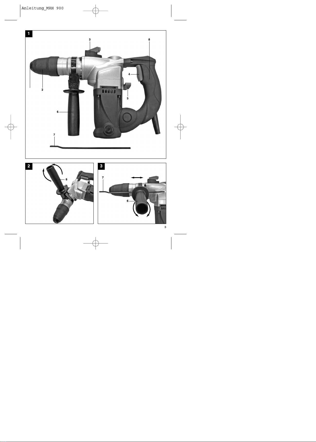
Additional information for electric power tools (looking from the handle) will release the clamp.
Turning the handle clockwise will tighten the clamp.
First release the additional handle clamp. You can
mWarning! then swing the additional handle (6) into the most
The specified vibration value was established in comfortable working position for you. Now turn the
accordance with a standardized testing method. It additional handle in the opposite direction again until
may change according to how the electric equipment the additional handle is secure.
is used and may exceed the specified value in
exceptional circumstances. 5.2 Depth stop (Fig. 3 – Item 7)
The depth stop (7) is held in place by the additional
The specified vibration value can be used to compare handle (6) by clamping. The clamp can be released
the equipment with other electric power tools. and tightened by turning the handle.
ŸRelease the clamp and fit the depth stop (7) in the
The specified vibration value can be used for initial recess provided for it in the additional handle.
assessment of a harmful effect
ŸSet the depth stop (7) to the same level as the drill
bit.
Keep the noise emissions and vibrations to a ŸPull the depth stop back by the required drilling
minimum. depth.
ŸTurn the handle on the additional handle (6) until it is
Ÿ Only use appliances which are in perfect working secure.
order.
ŸNow drill the hole until the depth stop (7) touches the
Ÿ Service and clean the appliance regularly. workpiece.
Ÿ Adapt your working style to suit the appliance.
Ÿ Do not overload the appliance. 5.3. Tool insertion (Fig. 4)
Ÿ Have the appliance serviced whenever necessary.
ŸClean the tool before insertion and apply a thin
Ÿ Switch the appliance off when it is not in use. coating of drill bit grease to the shaft of the tool.
Ÿ Wear protective gloves.
ŸPull back and hold the locking sleeve (2).
ŸInsert the dust-free tool into the tool mounting as far
Residual risks as it will go whilst turning it. The tool will lock itself.
Even if you use this electric power tool in ŸCheck that it is properly secure by pulling the tool.
accordance with instructions, certain residual
risks cannot be rules out. The following hazards 5.4 Tool removal (Fig. 5)
may arise in connection with the equipment's Pull back and hold the locking sleeve (2) and remove
construction and layout: the tool.
1. Lung damage if no suitable protective dust
is used. 5.5 Dust collection device (Fig. 6)
2. Damage to hearing if no suitable ear protection Slide the dust collection device (a) over the drill bit
used. before carrying out any hammer drilling vertically
3. Health damage caused by hand-arm vibrations above your head.
the equipment is used over a prolonged period
is not properly guided and maintained. 6. Starting up
5. Before starting the equipment
mImportant.
Before you connect the equipment to the mains To prevent all danger, the machine must only be
supply make sure that the data on the rating plate held using the two handles (6/8). Otherwise there
are identical to the mains data. may be a risk of suffering an electric shock if you drill
Always pull the power plug before making into cables.
adjustments to the equipment.
Check the drilling point for concealed electrical 6.1 Switching on and off (Fig. 1)
cables, gas and water pipes using a cable/pipe To switch on:
detector. Press the control switch (4).
5.1 Additional handle (Fig. 2 – Item 6) To switch off:
For safety reasons you must only use the Release the control switch (4).
hammer drill with the additional handle.
The additional handle (6) enables you to achieve 6.2 Hammer stop facility (Fig. 7)
better stability whilst using the hammer drill. The
machine must not be used without the additional The hammer drill has a hammer stop facility for
handle (6) for safety reasons. gentle initial drilling.
The additional handle (6) is secured to the hammer ŸTurn the rotary switch for the hammer stop facility (5)
drill by a clamp. Turning the handle anti-clockwise to position (B) to switch off the
7
GB