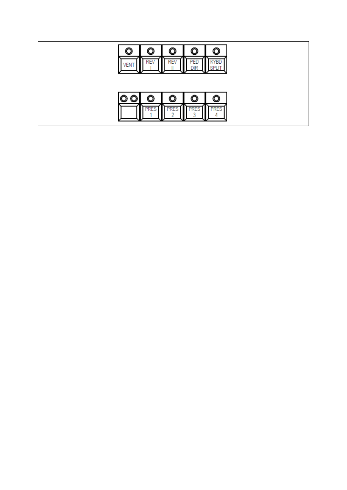
•VENT: This button inserts or removes the mini VENT from the signal path. When the LED is lit, the
mini VENT is inserted in the signal path; when the LED is off, the unprocessed signal is assigned to
both L and R/Mono outputs via a true bypass circuit.
•REV I and REV II: These buttons select the three available reverb algorithms (I + II = III) for the
Extra Sounds only. The intensity of each algorithm can be set through the external Programmer
Unit or the free Editor software.
•PED DIR: This button removes the pedal tones from the ROTARY (BAL) R/MONO + L outputs (and
from the Leslie™ interfaces if installed). The pedal tones remain available on the SUSTAIN/PEDALS
dedicated output if it has been set for this function through an internal jumper. When the LED is
off, the pedal tones are routed to the ROTARY R + L outputs; when the LED is lit, the pedal tones
are removed from the ROTARY R + L outputs.
•KYBD SPLIT: This button activates the keyboard split function.
In the C-1 model, the keyboard split function divides the keyboard into two parts at notes 25 and
26, allowing the lower manual tones to be played from the left part of the keyboard; or it can be
set through the external Programmer Unit or the free Editor software to allow the pedal tones to
be played from the left part of the keyboard.
In the C-2 model, the keyboard split function divides the lower keyboard into two parts at notes
25 and 26, allowing the pedal tones to be played from the left part of the lower keyboard. A
different split point can be selected by pressing a key on the lower keyboard while pressing the
KYBD SPLIT button.
•VENT SPEED (2 LEDs unlabeled): This button is mainly used for programming the mini VENT (see
the relevant section); the two LEDs flash to indicate the speed of the virtual rotors, with the
amber LED indicating the speed of the low-frequency drum rotor, and the red LED indicating the
speed of the mid/high-frequency horn rotor.
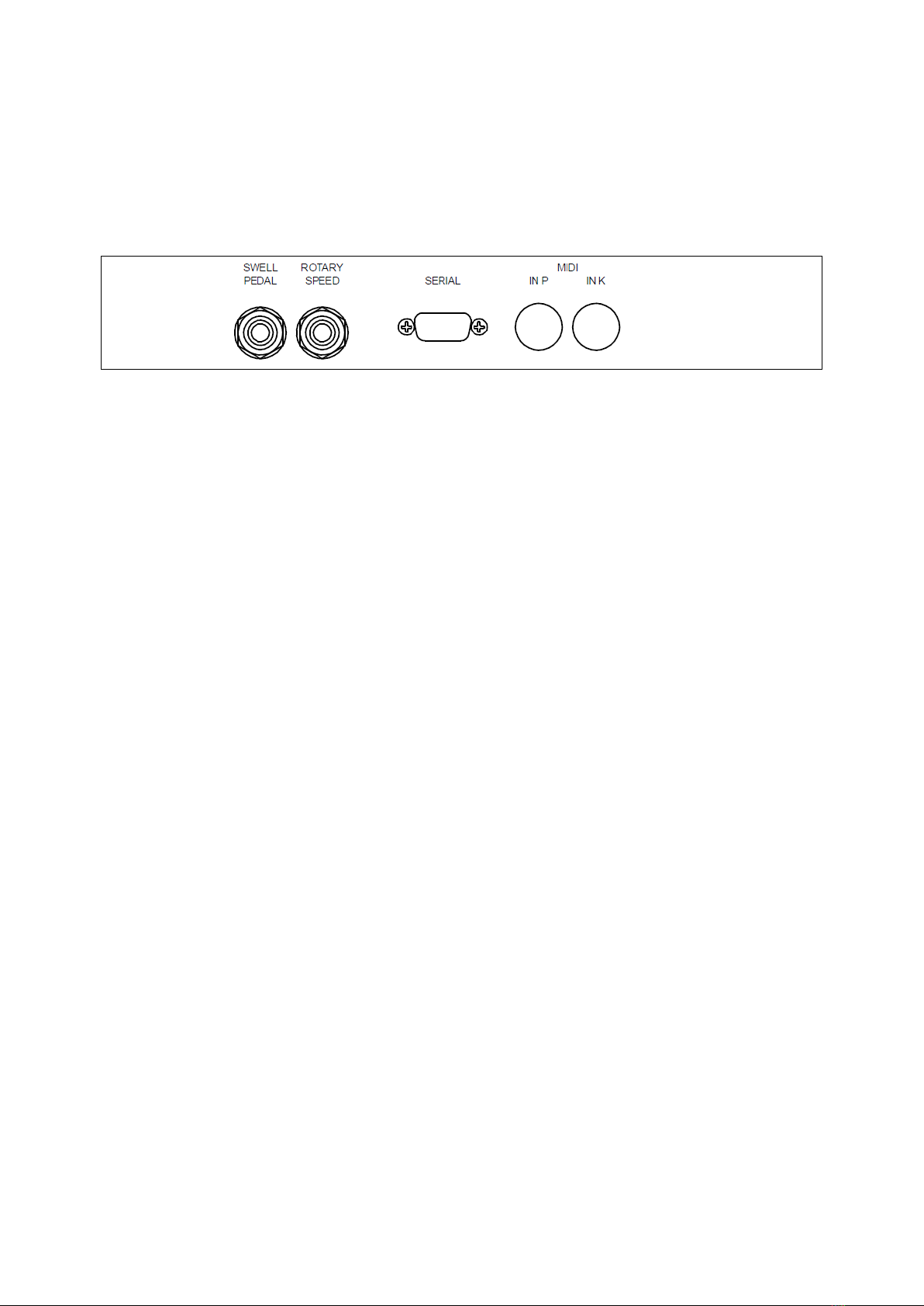
The speed of the mini VENT is ideally controlled by a footswitch plugged into the ROTARY SPEED
socket on the back panel, and it is fully synchronized with the speed of the Leslie™ interfaces if
installed. As noted above, this button is installed primarily for programming the mini VENT
presets, but if a footswitch is not available, then it is possible to control the speed of the mini
VENT with this button, although the speed changes will not be received by the Leslie™ interfaces
if installed.
Pressing this button will toggle between Fast and Slow, and pressing it together with the VENT
button will stop the rotors, which will always stop in the front position; pressing one of these two
buttons again returns the mini VENT to the previously selected speed.
Controlling the speed of the mini VENT directly with these buttons will not do any harm to the
organ or the mini VENT, but it will temporarily break the synchronization between the speed of