MAGAZIN SCHRANK P100 User manual

SCHRANK
P100
ANBAUELEMENT
Entwurf: MAGAZIN
Ein MAGAZIN-Produkt – entwickelt und produziert von MAGAZIN.

LIEFERUMFANG SCOPE OF DELIVERY
1× 3×
1×
1×
3×3×
1×18×3×1× 2× 3×
6×
1×
1×
1×
Abstand: 10mm
Abstand: 26mm
Abstand: 43mm
Abstand: 56mm
RÜCKWAND
MITTELWAND
TÜRBLATT
L
R
M
1×
1×
1×
1×
4×
X

MATERIAL MATERIAL
Gestell: Stahl, pulverbeschichtet; Platte: Biofaser Duplex (Herkunft: Europa) beidseitig weiß
melaminharzbeschitet oder natur, Bolzen: Kunststoff (POM)
Frame: steel, powder-coated, panel: Biofiber Duplex (origin: Europe) white melamin coated
or natural on both sides, bolts: plastic (POM)
MASSE MEASUREMENTS
B 62 × T 60,9 × H 207 cm
W 62 × D 60.9 × H 207 cm
GEWICHT WEIGHT
57 kg
57 kg
AUFBAUVARIANTEN STRUCTURE VARIANTS
2 MODULE 2 MODULES
MASSE MEASUREMENTS
B 124,5 × T 60,9 × H 207 cm
W 124.5 × D 60.9 × H 207 cm
GEWICHT WEIGHT
124 kg
124 kg
3 MODULE 3 MODULES
MASSE MEASUREMENTS
B 186,5 × T 60,9 × H 207 cm
W 186.5 × D 60.9 × H 207 cm
GEWICHT WEIGHT
186,5 kg
186.5 kg
4 MODULE 4 MODULES
MASSE MEASUREMENTS
B 248,5 × T 60,9 × H 207 cm
W 248.5 × D 60.9 × H 207 cm
GEWICHT WEIGHT
248.5 kg
248.5 kg

VORBEREITUNG PREPARATION
Draufsicht Top view Die Türen können mit dem
Anschlag auf der linken oder
rechten Seite angebracht wer-
den. Bitte legen Sie vorab fest,
zu welcher Seite sich jeweils die
Türen öffnen sollen. Der Pfosten
„M“ befindet sich dabei gegen-
über dem Pfosten „X“.
The doors can be installed with
the stop on the left or on the
right side. Please determine
in advance to which side the
doors should open in each case.
The post “M” is always located
opposite the post “X”.
Damit es bei der weiteren Mon-
tage nicht zu Fehlern kommt,
ist es hilfreich, zuerst in der
Zeichnung die spätere Position
der Türen einzuzeichnen bzw. zu
vermerken, auf welcher Seite der
Pfosten mit den Magneten „M“
montiert wird.
To avoid mistakes during further
assembly, it is helpful to first
mark the position of the doors
in the illustration and to note
on which side the post with the
magnets “M” will be mounted.
M!XM! XM!X
?
??
??
??
??
?

Die Scharniere für das Türblatt
und die Griffleiste mit dem Tür-
blatt verschrauben. Die Bohrun-
gen im Türblatt sind frontseitig
gesenkt, um die Schraubenköpfe
aufzunehmen. Griffleiste und
Scharniere an der Rückseite
ansetzen.
Screw the hinges for the door
leaf and the handle strip to the
door leaf. The drill holes on the
door leaf are countersunk at the
front to accommodate the screw
heads. Attach the handle strip
and hinges to the backside.
Zunächst bei allen 4 Rohren
die Stellfüße etwa 1 cm weit
ausdrehen.
First, unscrew the adjustable
feet of all 4 tubes by about 1
cm.
1
2
28 cm
3
MONTAGE ASSEMBLY
Die Rückwand mit dem rechten
„R“ und dem linken „L“ hinte-
ren Pfosten verschrauben. Die
geschlitzten Seiten der Pfos-
ten weisen dabei nach innen.
Die Bohrungen der Rückwand
sind einseitig gesenkt, um die
Schraubenköpfe aufzunehmen.
Die Pfosten an der Gegenseite
ansetzen.
Screw the back panel to the
right “R” and left “L” posts.
The slotted sides of the posts
face inwards. The drill holes on
the back panel are countersunk
on one side to accommodate the
screw heads. Attach the posts
on the opposite side.
R
L
MONTAGE ASSEMBLY

MONTAGE ASSEMBLY
Die Mittelwand mit einem der
vorderen Pfosten verschrauben.
Hier zunächst noch einmal
überprüfen, in welche Richtung
die Tür später geöffnet werden
soll bzw. auf welcher Seite der
Pfosten mit den Magneten „M“
montiert wird (siehe Skizze „Vor-
bereitung“).
Screw the centre panel to one
of the front posts. First check
again in which direction the
door is to be opened later, or on
which side the post with the ma-
gnets “M” is to be mounted (see
“preparation” illustration).
4
MONTAGE ASSEMBLY
Die zweite Seitenwand mit dem
zweiten vorderen Pfosten „X“
verschrauben (wie in Schritt 4).
In dem abgebildeten Beispiel
öffnet die Tür nach rechts.
Screw the second side panel to
the second front post “X” (as
shown in step 4).
In the illustrated example, the
door opens to the right.
5
56 cm
56 cm

7
MONTAGE ASSEMBLY
Zur Stabilisierung einen Fach-
boden oben einsetzen. Den
untersten Boden noch nicht
einsetzen, damit die Stellfüße
gut erreichbar bleiben.
Insert a shelf at the top for
stabilization. Do not insert the
bottom shelf yet so that the
levelling feet remain easily
accessible.
Setzen Sie nun die ersten vier
Fachbodenträger ein, indem
Sie diese auf einer Seite des
Pfostens in die länglichen
Aussparungen bis zum An-
stoß einstecken. Nun auch die
andere Seite des Trägers in die
gegenüberliegende Aussparung
einfügen. Die beiden unteren
Schlitze des Bodenträgers müs-
sen im Pfosten einrasten und
fest sitzen.
Now insert the first four shelf
supports by placing them into
the elongated cutouts on one
side of the post until they
are snug. Now also insert the
other side of the support into
the opposite recess. The two
bottom slots of the shelf support
must engage in the post and fit
tightly.
8
6
MONTAGE ASSEMBLY
Anschließend die Seitenwand
und Mittelwand an die Pfosten
der Rückwand schrauben.
Then screw the side panel and
middle panel to the posts of the
back panel.

10
MONTAGE ASSEMBLY
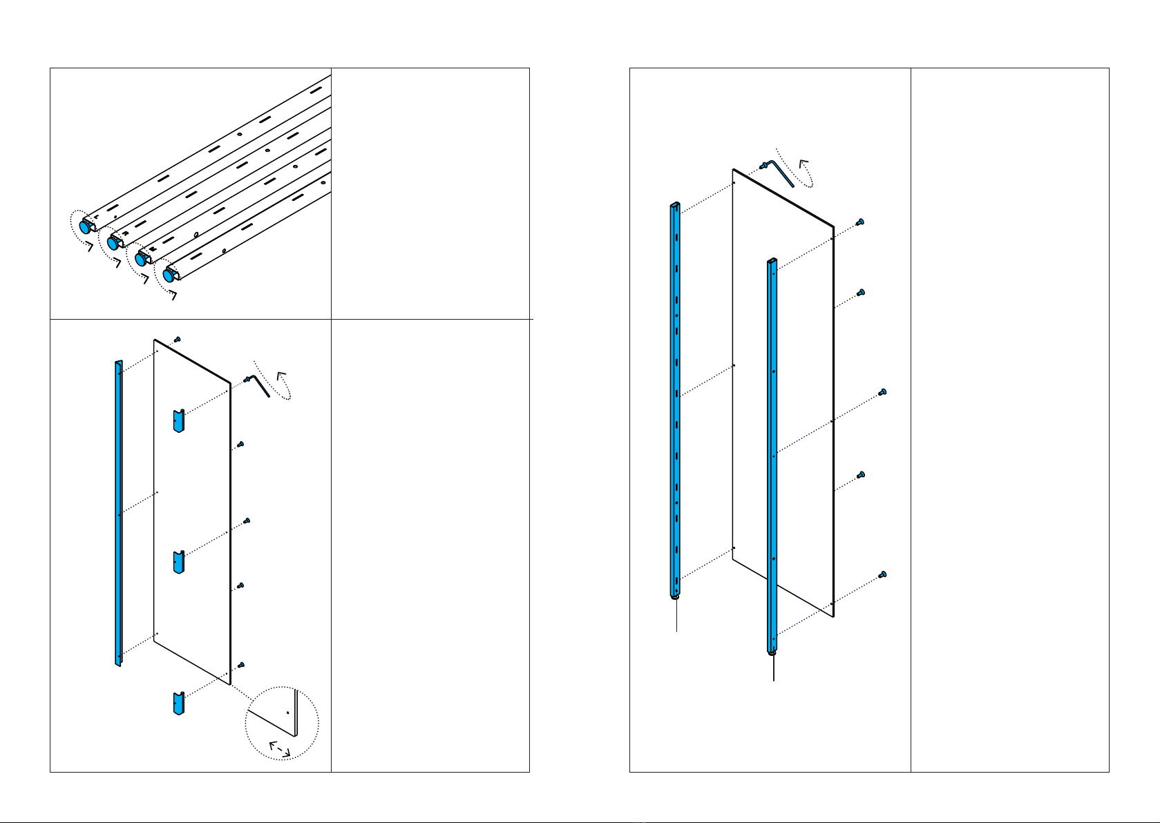
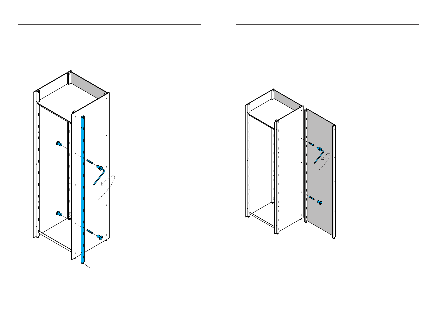
Nun eine weitere vormontierte
Rückwand (siehe Schritt 3)
anschrauben. Die Rückwand
ebenfalls mit 2 Gewindestiften
und 4 Rundmuttern mit Mittel-
wand und Pfosten des ersten
Schrankelements verbinden (wie
in Schritt 9).
Now set on another pre-moun-
ted back panel (see step 3). Also
connect the back panel to the
centre panel and the post of the
first cabinet element using 2 set
screws and 4 round nuts (as in
step 9).
MONTAGE ASSEMBLY
Nun wird ein weiterer Pfosten
an die Mittelwand angeschraubt.
Auch hier zunächst noch einmal
überprüfen, in welche Richtung
die Tür später geöffnet werden
soll bzw. auf welcher Seite der
Pfosten mit den Magneten „M“
montiert wird (siehe Skizze „Vor-
bereitung“).
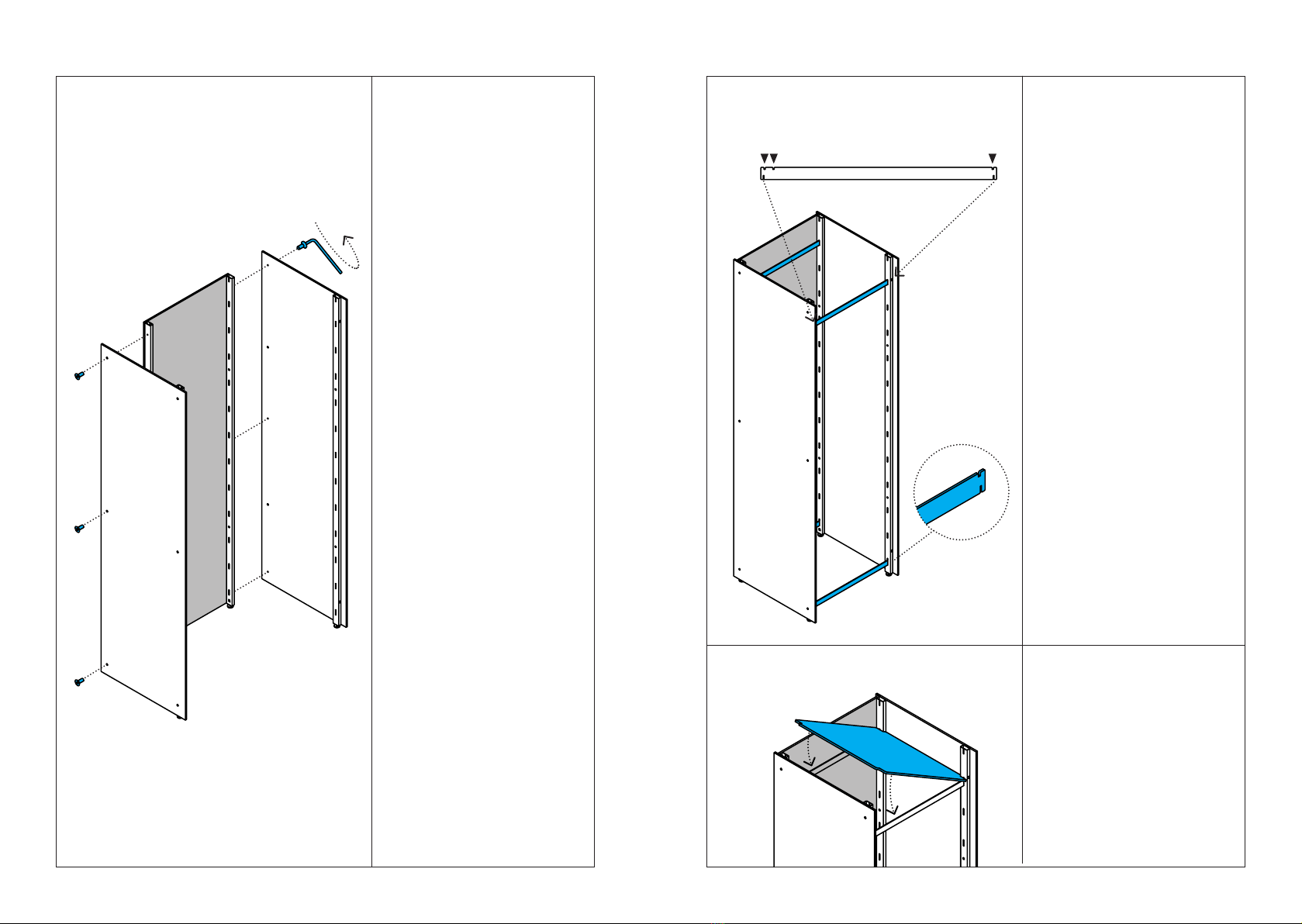
Den Pfosten mit 2 Gewindestif-
ten und 4 Rundmuttern mit Mit-
telwand und Pfosten des ersten
Schrankelements verbinden.
Now another post is screwed to
the centre panel. Again, first
check in which direction the door
is to be opened later, or on which
side the post with the magnets
“M” is to be mounted (see “pre-
paration” illustration).
Connect the post to the centre
panel and the post of the first ca-
binet element using 2 set screws
and 4 round nuts.
9
M?

MONTAGE ASSEMBLY
12
Setzen Sie nun die Fachboden-
träger ein, indem Sie diese
auf einer Seite des Pfostens in
die länglichen Aussparungen
bis zum Anstoß einstecken.
Nun auch die andere Seite
des Trägers in die gegenüber-
liegende Aussparung einfügen.
Die beiden unteren Schlitze des
Bodenträgers müssen im Pfosten
einrasten und fest sitzen.
Now insert the shelf supports by
placing them into the elongated
cutouts on one side of the post
until they are snug. Now also in-
sert the other side of the support
into the opposite recess. The two
bottom slots of the shelf support
must engage in the post and fit
tightly.
11
MONTAGE ASSEMBLY
Nun die Seitenwand mit der
Rückwand verschrauben.
Falls weitere Anbauelemente
verbaut werden, hier mit der
nächsten Mittelwand bzw.
Aufbauschritt 4 fortfahren. Die
verbleibende Seitenwand mit der
letzten Rückwand verschrauben.
Now screw the side panel to the
back panel.
If further add-on elements are to
be installed, continue here with
the next centre panel or assem-
bly step 4. Screw the remaining
side panel to the last back panel.

14
MONTAGE ASSEMBLY
Wenn alle Schrankelemente mit-
einander verbunden sind, kann
der Schrank final positioniert
werden. Die Konstruktion mit
einer Wasserwaage und unter
Justierung der Stellfüße aus-
richten.
When all the cabinet elements
are connected to each other, the
cabinet can be finally positio-
ned. Align the construction with
a spirit level and adjust the
levelling feet.
MONTAGE ASSEMBLY
13
Zur Stabilisierung die Fachböden
oben einsetzen. Die untersten
Böden noch nicht einsetzen,
damit die Stellfüße gut erreich-
bar bleiben.
Insert the shelves at the top
for stabilization. Do not insert
the bottom shelves yet so that
the levelling feet remain easily
accessible.

16
MONTAGE ASSEMBLY
Die Scharniere für die jeweili-
ge Tür in die entsprechenden
Bohrungen des vorderen Pfostens
montieren. Dazu die Schrauben
mit Unterlegscheibe von innen
durch die Bohrungen im Pfosten
stecken und das Scharnier außen
anschrauben. In das oberste
Scharnier den Doppelbolzen ein-
stecken.
Mount the hinges for the door in
the corresponding holes in the
front posts. To do this, insert the
screws with washers from the
inside through the holes in the
post and screw the hinge on the
outside. Insert the double bolt
into the top hinge.
15
MONTAGE ASSEMBLY
Die oberen Fachbodenträger und
die Deckel einsetzen.
Auch alle weiteren Zusatzartikel
(Schubkästen, Garderoben-
stangen, weitere Fachböden)
an den gewünschten Positionen
einsetzen. Dazu die jeweiligen
Anleitungen beachten.
Insert the upper shelf supports
and the cover plates.
Also insert all other additional
accessories (drawers, clothes
rails, additional shelves) at the
desired positions. Follow the
respective instructions.

18
MONTAGE ASSEMBLY
Die Einsteckbolzen in die
unteren Scharniere stecken. Alle
weiteren Türen in der gleichen
Reihenfolge einsetzen.
Abschließend prüfen, ob die
Türen gleichmäßig schließen und
von den Magneten geschlossen
gehalten werden. Gegebenen-
falls sollte der Schrank mit einer
Wasserwaage nachjustiert werden
(siehe Schritt 14). Für eine
einfachere Nachjustierung und
leichteren Zugriff auf die Stell-
füße kann der unterste Einlege-
boden entfernt werden.
Insert the insertion bolts into
the lower hinges. Insert all other
doors in the same order.
Finally, check if the doors close
evenly and are held closed by the
magnets. If necessary, the cabi-
net should be readjusted using
a spirit level (see step 14). The
lowest shelf can be removed for
easier readjustment and access
to the levelling feet.
17
MONTAGE ASSEMBLY
Die Tür auf den Doppelbolzen
aufsetzen. Die Tür dabei unten
leicht zur Seite schwenken,
damit sie nicht auf den unteren
beiden am Pfosten montierten
Angeln aufsetzt.
Place the door on the double
bolt. While doing so, swing the
door slightly to the side at the
bottom so that it does not rest on
the lower two hinges mounted on
the post.

MAGAZIN Versandhandelsgesellschaft mbH
Lautenschlagerstraße 16
70173 Stuttgart
www.magazin.com
Stand: Juli 2023 Status: July 2023
HINWEIS NOTE
Wir empfehlen die Wandsicherung UNIVERSAL (Artikelnummer 35018) aus unserem Sorti-
ment. Diese kann in die vorgesehenen Bohrungen an der Rückseite des Schrankes eingesetzt
werden.
We recommend the wall mount UNIVERSAL (article number 35018). This can be inserted
into the drill holes provided on the back of the cabinet.
PFLEGEHINWEIS CARE INSTRUCTIONS
Die Reinigung erfolgt mit einem Staubtuch.
It is cleaned by using a duster.
Other manuals for SCHRANK P100
1
Table of contents
Other MAGAZIN Indoor Furnishing manuals
Popular Indoor Furnishing manuals by other brands

Rockler
Rockler Blum 55879 instructions

Ergotron
Ergotron 97-540-053 user guide

Comfort Products
Comfort Products Onespace Colletta 50-190105 Assembly instructions

Studio Designs
Studio Designs HOME 71001 Assembly instructions

Safavieh Furniture
Safavieh Furniture Henley DSK2100 quick start guide

Gymnova
Gymnova 3425 Assembly instructions

Stratco
Stratco TITANIUM SS-10215 Assembly guide

Castleton Home
Castleton Home Barstool 2 Product instructions

ROOMS TO GO
ROOMS TO GO E180D-30 Assembly instruction

Powell
Powell Bombay Heritage 851-235 Assembly instructions

baby&child
baby&child BELLINA DRESSER TOPPER quick start guide

Contour
Contour TOPO Assembly guide