Magen eco-Energy resilience D Series User manual

Table of Contents
Resilience D Installation guide. © 2016, all rights reserved P a g e | 1
35405055 | December 2016
www.magen-ecoenergypool.com

Preface
Resilience D Installation guide. © 2016, all rights reserved P a g e | 2
PREFACE
Resilience D (model PSC5) is an automatic natural chlorine generator for pool sanitation. The system uses a very low
concentration of salt (less than the concentration in a human teardrop) and converts it into free chlorine that
destroys algae and bacteria in the pool. After removing the algae and bacteria, the chlorine reverts back into salt. This
process of purification continues, making the need of adding extra sanitizing chemicals to the pool virtually
unnecessary.
Congratulations on the purchase of your Resilience D Chlorine Generator. Your purchase will minimize the efforts
needed to maintain your pool and maximize your enjoyment. Before installation or operation, please take the time to
read this entire manual, compare package contents with the parts list, and gather tools required. Improper
installation may void the warranty and create unnecessary hazards. This manual contains step-by-step instructions to
help ensure that your installation meets the recommended standards. Spending the time to understand your system
and its functions will assure successful, trouble-free operation. If you are unsure about any of the information in this
manual, please contact your installer/dealer. When working around your pool, please take care to avoid hazards such
as electrical wires and chemicals. CAUTION! Safety comes first!
SAFETY INSTRUCTIONS
Read and follow all instructions
All electrical work must be performed by a licensed electrician and conform to all national, state, and local codes.
Improper use or installation can badly harm the unit and its surroundings. When installing and using electrical
equipment, basic safety precautions should always be followed, including the following:
DO NOT OPEN THE DISPLAY COVER OF THE CONTROL BOX –NOT A SERVICABLE UNIT.
● Disconnect all AC power before installation.
● WARNING –to reduce the risk of injury, do not permit children to use this product.
● The Control Box must be mounted vertically on a flat surface and at a minimum horizontal distance of 1.5
m (5ft) (or more, if local codes require so) from the pool.
● WARNING –risk of electric shock! Connect only to a grounding type circuit protected by a ground-fault
circuit-interrupter (GFCI) outlet. The installer should provide this GFCI requirement. The GFCI should be
rated for minimum 6 Amps and tested on a regular basis by pushing the test button. If the GFCI fails to
operate correctly, there is ground current flowing indicating the possibility of electric shock. Do not use this
unit. Disconnect unit and have a qualified professional fix the problem before using.
● The Input circuit (LN1 & N/LN1) must be connected only after OVERCURRENT DEVICES, such as fuse or
circuit breaker to limit the amperage in the input wire to the maximum that is permitted by the National
Electrical Code.
● The Unit must be permanently connected, with copper wire, not less than 1.5 mm²(14 Awg).
● Do not bury the cord. Place the cord so to minimize damage by lawn mowers, hedge trimmer and other
equipment.
● WARNING! To reduce the risk of electric shock, replace a damaged cord immediately.
● WARNING! To reduce the risk of electric shock, do not use an extension cord to connect the unit to
electric power supply; provide a properly located outlet.

Preface
Resilience D Installation guide. © 2016, all rights reserved P a g e | 3
● Wiring of the unit must be performed according to the wiring instructions detailed in this manual or on
the front box cover.
● Build-up of flammable fumes can result in a hazardous condition if the cell is allowed to operate without
flow. This device must be operated only with the original in-line flow sensor.
● The Flow Sensor must be installed between the last piece of apparatus and the cell.
● Ensure that equipment and materials used in or around the pool and spa are compatible with salt-based
sanitation systems. Certain materials may be susceptible to salt and chlorine damage.
● ALWAYS ADD ACID TO WATER, NEVER WATER TO ACID.
● Make sure the pool's machine room is properly vented to avoid damage from acid vapors.
● Under no circumstances should the machine room be used to store equipment, furniture, sports gear or
any other equipment that is not related to the pool including spare acid containers. The machine room must
be aired and vented prior to entering it.
● Acid container must be stored inside a spill containment vessel (a basin to hold acid in case of overflow or
tipping of the acid container).
● KEEP THESE INSTRUCTIONS.

Preface
Resilience D Installation guide. © 2016, all rights reserved P a g e | 4
TABLE OF CONTENTS
PREFACE ....................................................................................................................................................................................... 2
safety instructions ............................................................................................................................................................................2
PACKAGE CONTENTS ....................................................................................................................................................................6
Additional materials required (not supplied in package) ................................................................................................................. 6
SYSTEM OVERVIEW ...................................................................................................................................................................... 7
PLUMBING CONFIGURATIONS...................................................................................................................................................... 8
CELL PLUMBING (WITHOUT DOSING ACID PUMP) ........................................................................................................................ 8
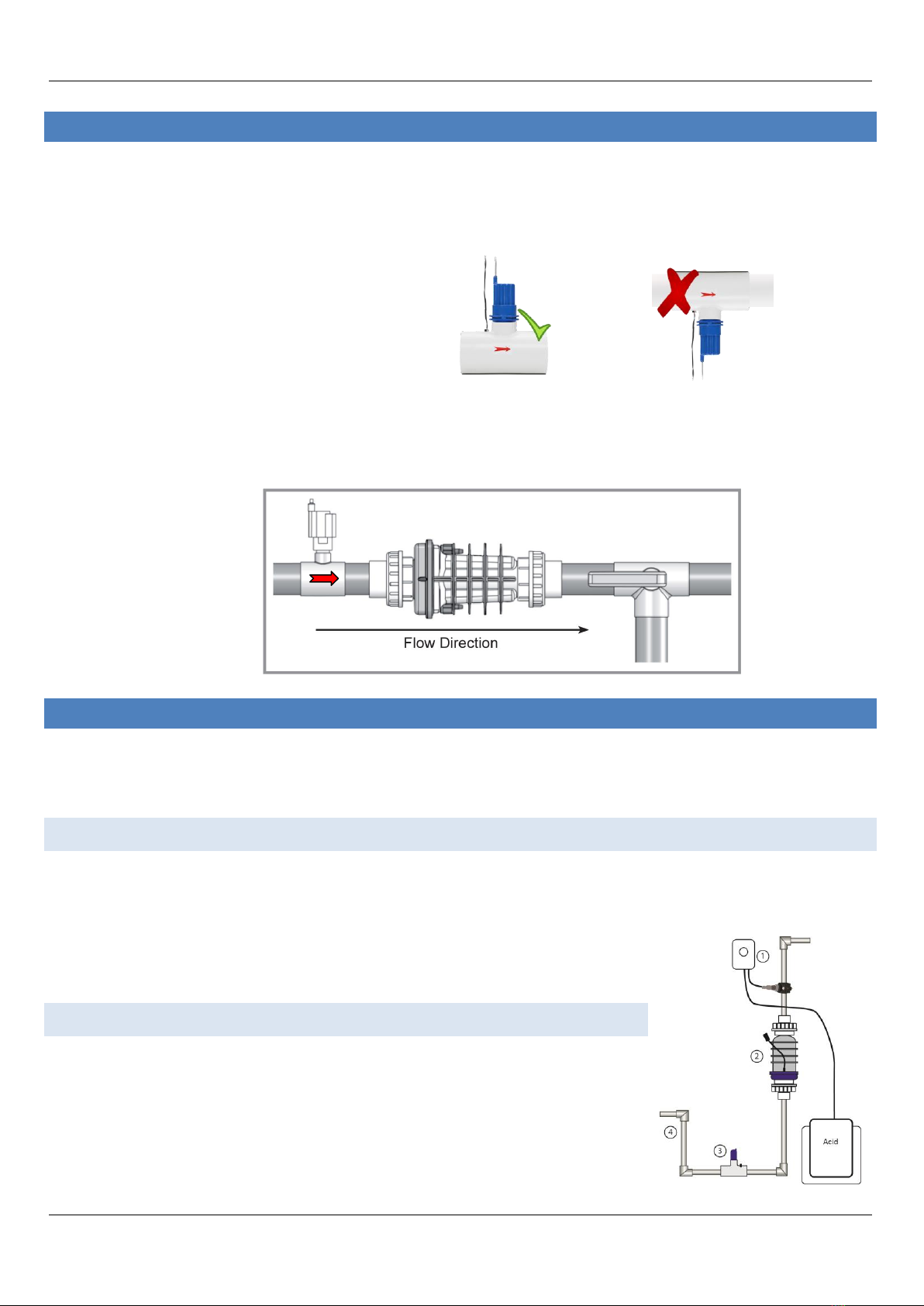
INSTALLING THE FLOW SENSOR.................................................................................................................................................... 9
CELL PLUMBING (WITH A DOSING ACID PUMP) ............................................................................................................................ 9
Installing the dosing acid pump ........................................................................................................................................................9
U Shape plumbing configuraiton ......................................................................................................................................................9
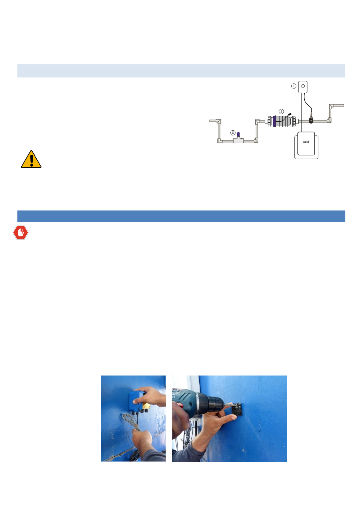
Horizontal plumbing configuration.................................................................................................................................................10
INSTALLATION OF DOSING ACID PUMP ...................................................................................................................................... 10
MOUNTING THE CONTROL BOX.................................................................................................................................................. 13
ELECTRICAL WIRING OF THE CONTROL BOX................................................................................................................................ 14
WIRING THE CELL........................................................................................................................................................................ 15
WIRING THE FLOW SENSOR ........................................................................................................................................................ 15
WIRING THE TEMPERATURE SENSOR.......................................................................................................................................... 16
WIRING THE DOSING ACID PUMP............................................................................................................................................... 16
WIRING THE POOL COVER INDICATION ...................................................................................................................................... 16
STARTING UP.............................................................................................................................................................................. 17
Before adding the salt.....................................................................................................................................................................17
Adding the salt ................................................................................................................................................................................ 18
Calculating the size of the pool ..................................................................................................................................................18
What type of salt should I use? .................................................................................................................................................. 18
Salinity demand table (in kg.) .....................................................................................................................................................19
OPERATING INSTRUCTIONS ........................................................................................................................................................ 20
Filtration ......................................................................................................................................................................................... 20
Related chemistry....................................................................................................................................................................... 20
BASIC OPERATION ...................................................................................................................................................................... 21
Turning the unit on ......................................................................................................................................................................... 22
Operating actions ...........................................................................................................................................................................23
Increasing chlorine output .........................................................................................................................................................23
Decreasing chlorine output ........................................................................................................................................................23
Turbo setting .............................................................................................................................................................................. 23
Mode changing........................................................................................................................................................................... 23
Automatic ST:BY Mode...............................................................................................................................................................23

Preface
Resilience D Installation guide. © 2016, all rights reserved P a g e | 5
Salinity readout...............................................................................................................................................................................24
Normal salt level.........................................................................................................................................................................24
High salinity indication ...............................................................................................................................................................24
Low salinity indication ................................................................................................................................................................ 25
Turbo setting .............................................................................................................................................................................. 25
Pool cover function......................................................................................................................................................................... 26
Error messages ...............................................................................................................................................................................27
NO FLOW .................................................................................................................................................................................... 27
HIGH TEMPERATURE IN THE UNIT ............................................................................................................................................. 27
LOW TEMP..................................................................................................................................................................................27
SHRT CELL ................................................................................................................................................................................... 27
NO CELL ...................................................................................................................................................................................... 28
NEED PUMP ................................................................................................................................................................................ 28
ACID PIPE .................................................................................................................................................................................... 28
PH CONTROL............................................................................................................................................................................... 29
pH reducing mode ..........................................................................................................................................................................29
pH reducing: Auto ......................................................................................................................................................................29
pH reducing: Manual .................................................................................................................................................................. 29
Cell cleaning mode..........................................................................................................................................................................30
Adjusting the frequency of the cleaning ....................................................................................................................................30
Immediately initiating a cell cleaning ......................................................................................................................................... 30
ACID PIPE reminder ........................................................................................................................................................................31
MAINTENANCE ........................................................................................................................................................................... 31
Cell maintenance ............................................................................................................................................................................31
Cell cleaning ............................................................................................................................................................................... 31
Cleaning using the cleaning cap .................................................................................................................................................32
WINTERIZING ............................................................................................................................................................................. 32
SPRING STARTUP ........................................................................................................................................................................ 32
REPLACING THE PREISTALTIC TUBE OF THE DOSING ACID PUMP................................................................................................ 33
UNDERSTANDING THE CHEMISTRY............................................................................................................................................. 35
SATURATION INDEX.................................................................................................................................................................... 37
TROUBLESHOOTING ................................................................................................................................................................... 38
DOSING ACID PUMP TROUBLESHOOTING................................................................................................................................... 43

Package contents
Resilience D Installation guide. © 2016, all rights reserved P a g e | 6
PACKAGE CONTENTS
Please unpack your new controller carefully. Do not use a knife or sharp instrument to remove contents. Enclosed in
the packing you should find the following:
If purchased with the system, dosing acid pump kit includes: 2 saddles (50 + 63mm), 3/8" to 1/2" adaptor,
none return valve, internal replacement tube, 2 x 3m polyethylene tube, foot filter and weight.
ADDITIONAL MATERIALS REQUIRED (NOT SUPPLIED IN PACKAGE)
1. PVC solvent cement and priming fluid
2. Hacksaw or pipe cutters and petroleum jelly
3. Screwdrivers
4. Drill needed for systems with 1½ inch plumbing
5. Conduit
6. Silicone lubricant (DO NOT use silicone glue)
7. Pipe adaptors (i.e. reducer couplings)
8. High voltage wires (copper conductors only)
Control Box
Flow Switch T &
Temp Sensor
Dosing acid pump
(Only if purchased with the system)
4 PVC hose reducer
couplings
Cell

System overview
Resilience D Installation guide. © 2016, all rights reserved P a g e | 7
SYSTEM OVERVIEW
This installation manual is designed for the pool professional. It assumes the installer has a working knowledge of
basic pool-service operations. It is based on actual field installations and the natural flow of progress found to be
most efficient.
The Natural Chlorine Generator consists of 4 main units: Control box, Cell, Flow Sensor and dosing acid pump (if
purchased with the unit). These assemblies are manufactured using to most advanced corrosion resistant materials
that are extremely durable. Installing them in an area that is sheltered from the sun and water will protect them from
extreme weather conditions.
SAFETY MEASURES
1. Operate the system ONLY with the original flow sensor supplied with the system.
2. See important safety instructions on page 2 of this manual.
1. Power/Timer
2. Pump
3. Control Box
4. Flow switch
5. Water temperature sensor
6. Heater (optional)
7. Cell
8. Dosing acid pump (optional)
Water from pool
Pool return line

Plumbing configurations
Resilience D Installation guide. © 2016, all rights reserved P a g e | 8
PLUMBING CONFIGURATIONS
CELL PLUMBING (WITHOUT DOSING ACID PUMP)
1. The cell and flow sensor must be installed downstream from the filter and heating devices before any Tees in
the return line. The cell may be installed horizontally or vertically as long as is pointing in the flow direction
(i.e. into the blue and out of the clear side).
2. Approximately 380 mm (15 inches) of pipe length is required for a horizontal installation for the flow sensor
and cell. Vertical installations may require less pipe length.
3. On the pipe where the cell is installed, mark two lines 300 mm (11 3/4 inches) apart and cut out using a
hacksaw or pipe cutter.
4. Unscrew and remove the barrel unions (i.e. barrel nuts and slip connections) from either end of the Cell.
Thread one of the barrel nuts over the pipe and glue its slip connection to the cut pipe.
5. Hold up the cell with the second unions to gauge the proper distance before threading the second nut and
gluing the second clip.
6. After letting sufficient drying time for the glue, place the cell with the O-rings into the opening between the
two ends of the pipe and tighten the unions making sure that the cell is installed with the arrow pointing in
the direction of the flow (i.e. water should enter from the side with the blue cap).

installing the flow sensor
Resilience D Installation guide. © 2016, all rights reserved P a g e | 9
INSTALLING THE FLOW SENSOR
1. The flow sensor must be installed before the cell. Make sure that there is no valve between the cell and the
flow sensor. The flow sensor may be installed vertically, in an angle, but MUST NOT be installed upside down.
This could cause debris to settle in the flow sensor body and restrict the paddle movement.
2. Clean and glue the Tee connector (included) to the pipe, making sure that the threaded end with the sensor is
on the pipes topside (as illustrated here ->).
3. Make sure that the arrow at the top of the flow sensor points in direction of the flow and that no glue or
pipe cleaner touches the paddle inside the sensor as it may cause it to jam. Double check that the flow
sensor operates properly by reducing the flow for five seconds and checking if the low flow indicator on the
control box lights.
CELL PLUMBING (WITH A DOSING ACID PUMP)
The dosing acid pump is a unique acid injection pump that automatically cleans the cell and reduces the pH water
levels. Only the PSC-5 control box can operate this unit.
INSTALLING THE DOSING ACID PUMP
The dosing acid pump should be installed right after the chlorinator cell, in a way that ensures the cell stays full of
water when the circulation pump turns off. Choose one of the plumbing configuration options below:
A. U shape installation
B. Horizontal installation
U SHAPE PLUMBING CONFIGURAITON
1. Dosing acid pump and saddle
2. Chlorinator cell
3. Flow switch Tee

Installation of dosing acid pump
Resilience D Installation guide. © 2016, all rights reserved P a g e | 10
4. ~54 cm (21 inch) straight 2" PVC pipe for keeping the cell filled with water when there is no flow in the line.
HORIZONTAL PLUMBING CONFIGURATION
1. Dosing acid pump
2. Chlorinator Cell
3. Flow Switch Tee
The examples illustrated above are with the dosing acid pump installed. A plumbing trap is required to keep
the cell flooded with water when the dosing acid pump washes the cell during the circulation pump downtime.
Create the trap so the acid injected by the dosing acid pump will be focused on the cell and not flow back to the
pool or equipment set. If installing without the dosing acid pump, we recommend following the same examples
as above and leaving room for adding the dosing acid pump in the future.
INSTALLATION OF DOSING ACID PUMP
Disconnect ALL power before work commences.
Open the control boxes' lid to make sure the unit is turned OFF.
It is recommended to wear rubber or polyethylene protective gloves and safety glasses. It is also advisable
to protect your clothes or wear dispensable ones.
Make sure the pool's machine room is properly vented to avoid damage from acid vapors.
Under no circumstances should the machine room be used to store equipment, furniture, sports gear or any
other equipment that is not related to the pool, including spare acid containers. The machine room must be
aired and vented prior to entering it.
Acid container must be stored inside a spill containment vessel (a basin to hold acid in case of overflow or
tipping of the acid container).
1. Determine the location where you wish to install the acid pump on the wall.
2. Check that the all components: electrical wiring, tubes etc. reach their position.
3. Drill and attach the acid pump's clip to the wall and hang the pump on it.

Installation of dosing acid pump
Resilience D Installation guide. © 2016, all rights reserved P a g e | 11
4. Open the control box service panel.
5. Find the acid pump connection point marked "acid pump". Insert the signal cable that originates from the
pump through the hole at the bottom of the control box and connect it to the acid pump terminal. Make sure
the cable is secured and reattach the service panel's cover (see wiring the dosing acid pump, page 14).
6. Wire the electrical cable of the acid pump to the main power source in the machine room (240V) parallel to
the circulation pump. This must be performed by a licensed electrician!
7. Establish the pipe diameter you have installed and make sure you have the correct pipe saddle (50 or 63mm).
8. Acid pump's pipe saddle must be installed right after the electrolysis cell.
9. With the proper sized saddle for your piping, locate the position where the acid will be infused through and
drill a 9mm hole in the pipeline.
10. Turn the top part of the saddle and make sure the seal is properly placed. Position the two parts over the hole
you just drilled.
11. Insert the two screws through the saddle's holes and tighten them
(13 mm wrench is needed).
12. Wrap the threads of the saddle fitting adapter (½to ⅜) with Teflon tape and thread it into the acid pipe
saddle.
13. Wrap the injector non-return valve threads with Teflon tape and thread it into the saddle fitting adapter.
Seal

Installation of dosing acid pump
Resilience D Installation guide. © 2016, all rights reserved P a g e | 12
14. Cut the supplied tube to the required length - this will become the injection tube. Attach one end to the outlet
of the acid pump (right side) and the other end to the injector non-return valve attached to the pipe.
Note the arrows impressed on the acid pump transparent cover indicating the suction and injection
direction of the acid.
15. Cut another piece of tube to the required length - this will become the suction tube. Attach one end to the
inlet of the acid pump (left side).
16. Thread the other end other suction tube through the lid of the acid container and attach to it the weight and
foot filter.
17. Close the lid of the acid container and make sure the suction tube cannot be pulled out of the container.
18. Place the acid container inside a spill container vessel (a basin to hold acid in case of overflow or tipping o the
acid container).
19. Place the acid container and spill container vessel in a safe place and in such a way that it cannot cause
damage if it falls. Make sure it is positioned away from children!

Mounting the control box
Resilience D Installation guide. © 2016, all rights reserved P a g e | 13
20. Turn the control box on. Manually operate the acid pump in manual mode for a number of minutes.
21. Make sure the red light on the pump is on, that it is spinning and that acid it sucked from the acid container
and injected to the pipe.
After the system has been started, make sure to check the dosing acid pump and all connections for leaks.
MOUNTING THE CONTROL BOX
1. The control box must be mounted vertically on a
flat surface, and a minimum horizontal distance of
1.5 m (5 ft) (or more, if local codes require) from
the pool.
2. Select a location for your control box within 3½
meters (10 ft) from the intended cell and flow
switch installation, to ensure that enough cable is
available (the actual cable length is 3.7 m/ 12 ft)
3. Secure the unit on the wall using the enclosed
screws and anchors. Use 8 mm (¼") drill bit for
the anchor holes.
4. Remove the access cover at the lower part of the
control box by opening the two screws holding it
in place.
5. Hardwire the power cable to the time clock as indicated in the instructions below.

Electrical wiring of the control box
Resilience D Installation guide. © 2016, all rights reserved P a g e | 14
CAUTION
-Do not mount the system above a heater, inside a panel or tightly enclosed area. This can overheat and
damage the system.
-Do not block the vents of the control box, located at its back.
ELECTRICAL WIRING OF THE CONTROL BOX
CAUTION!
-Disconnect all power supply to the main timer/main power source before hardwiring the input voltage cables
to the timer and control box.
-Hardwire all accessory equipment: dosing acid pump, Temp sensor etc. and close the access cover before
resupplying main high voltage to the unit.
Wiring for a system with the dosing acid pump
1. Input high voltage terminals
2. Cell connectors
3. Flow switch socket (blue)
4. Water temperature sensor socket
(white)
5. Dosing acid pump socket (red)
6. Pool cover input
7. Access cover

Wiring the cell
Resilience D Installation guide. © 2016, all rights reserved P a g e | 15
Alternative wiring (only if not planning to use dosing acid pump)
WIRING THE CELL
Ensure that the connections are perfectly clean from any debris. Connect the two black wires from the control box to
the connectors at the sides of the cell until they "click" together.
NOTE: do not extend the original cables leading to the cell. This decreases the system efficiency and will void
warranty coverage.
WIRING THE FLOW SENSOR
Locate the flow sensor terminals at the lower part of the control box. Insert the flow switch cable through the
connector hole in the lower part of the control box, and plug it into the flow sensor socket. Tighten the threaded
adaptor firmly, until the cable cannot be pulled out from the box.

Wiring the temperature sensor
Resilience D Installation guide. © 2016, all rights reserved P a g e | 16
WIRING THE TEMPERATURE SENSOR
Locate the temperature sensor terminals in the lower part of the control box. Insert the temperature sensor cable
through the connector hole in the lower part of the control box and plug it into the temperature sensor socket.
Tighten the threaded adaptor firmly, until the cable cannot be pulled out from the box.
WIRING THE DOSING ACID PUMP
Locate the terminals marked "acid pump" in the lower part of the main control box. Insert the dosing acid pump
"signal" cable (marked and has red connector) through the connector hole in the lower part of the control box and
plug it into the acid pump socket. Tighten the threaded adaptor firmly until the cable cannot be pulled out from the
box.
The second cable marked "power" can be wired in two ways:
1. Wire the electrical cable of the acid pump to the main power source in the machine room (240V) parallel to
the circulation pump. This must be performed by a licensed electrician!
OR
2. Insert the "power" cable through the connector in the lower part of the control box. Wire one strand to the
left most socket. The remaining strand should be connected to one of the center sockets.
Gently pull on the cable to make sure it is secured well.
WIRING THE POOL COVER INDICATION
Hardwire 2 wires that deliver dry contact signal from the pool cover control to the "pool cover" terminals in the lower
part of the control box. Make sure to use a proper strain relief (PG/Heyco) that will not enable that cable from being
pulled out from the control box.
Power

Starting up
Resilience D Installation guide. © 2016, all rights reserved P a g e | 17
STARTING UP
BEFORE ADDING THE SALT
1. Balance the chemicals: See the section titled "Understanding the chemistry" on page 35 for recommended
water balance. Remove metals from the water using a phosphate-free metal remover and test the water to
ensure that phosphate levels are lower than 100 ppb (parts per billion). This will ensure that the transition to
the natural chlorine generator system is quick and reliable.
2. New Pools: wait 30 days or longer if specified by your pool builder, for plaster to cure before adding salt or
operating the natural chlorine generator.
3. Biguanide Pools: if installing the system in a pool that has Biguanide sanitizers, all Biguanide must be
removed prior to system startup.
4. Now that your new controller has been physically installed, water chemistry should be tested and adjusted
prior to initiating automated control of the pool. Check that your pool water conforms to the following
ranges before powering on and setting up the Resilience D Plus.
IMPORTANT! It is compulsory to control and adjust water balance parameters BEFORE operating the system.
Test
Minimum
Ideal
Maximum
Salt
3000
3500
4500
pH
7.0
7.5
7.8
Free Chlorine (ppm)
1
2
3
Bromine (ppm)
2
3
4
Stabilizer - Cyanuric Acid
(ppm)
20
-
70
ORP (mV)
650
720
850
Total Alkalinity
80
-
120
Calcium Hardness
200
-
400

Starting up
Resilience D Installation guide. © 2016, all rights reserved P a g e | 18
ADDING THE SALT
1. Measure the pre-existing salinity of your pool. Previous chlorine use may cause the salinity reading to be
higher due to residual salt in the chlorine.
2. Determine how much salt is needed from the Salinity Demand Table on the page 19. This table is based on a
salt concentration of 3500 ppm (approximately ⅓%). More may be added for larger pools (e.g. 4000 ppm).
3. Keep the circulating pump on.
4. Distribute the determined amount of salt evenly around the pool. To avoid clogging the filter or damaging the
control box and pump, do not add salt through the skimmer or surge tank. Brush the bottom to help dissolve
the salt.
5. The readout on the chlorine generator may fluctuate until the salt is fully dissolved.
6. Turn the control box OFF. Failure to do so will cause the fuse to blow.
7. Keep the pump on to circulate the water.
8. Distribute the required amount of salt evenly around the pool. It will take about 8 hours for the salt to
disperse evenly in the water.
9. Once the salt has fully dissolved, adjust the chlorinator to the desired setting.
Calculating the size of the pool
Liters (dimensions in meters)
Gallons (dimensions in feet)
Rectangular
Length X Width X Average Depth X 1000
Length X Width X Average Depth X 7.5
Round
Diameter X Diameter X Average Depth X 785
Diameter X Diameter X Average Depth X 5.9
Oval
Length X Width X Average Depth X 893
Length X Width x Average Depth X 6.7
What type of salt should I use?
Good
Bad –do not use!
The best salt is an evaporated, granulated pool
salt
Iodized salt
99.9% pure salt
Salts with more than 1% anti caking agents (e.g. yellow
prussiate of soda or sodium ferrocyanide) –because they
contain iron and will yellow the fittings. These anti caking
agents are commonly found in water softener salts
Rock salt –because of the dirt mixed with the rock salt
Calcium chloride- is not a salt. Use only sodium chloride

Starting up
Resilience D Installation guide. © 2016, all rights reserved P a g e | 19
Salinity demand table (in kg.)
Salt level before addition (in ppm)
0
500
1000
1500
2000
2500
3000
3500
4500
How much salt to add? (In kg.)
10
40
35
30
25
20
15
10
5
0
20
80
70
60
50
40
30
20
10
0
30
120
105
90
75
60
45
30
15
0
40
160
140
120
100
80
60
40
20
0
50
200
175
150
125
100
75
50
25
0
60
240
210
180
150
120
90
60
30
0
70
280
245
210
175
140
105
70
35
0
80
320
280
240
200
160
120
80
40
0
90
360
315
270
225
180
135
90
45
0
100
400
350
300
250
200
150
100
50
0
110
440
385
330
275
220
165
110
55
0
120
480
420
360
300
240
180
120
60
0
130
520
455
390
325
260
195
130
65
0
140
560
490
420
350
280
210
140
70
0
150
600
525
450
375
300
225
150
75
0
160
640
560
480
400
320
240
160
80
0
170
680
595
510
425
340
255
170
85
0
180
720
630
540
450
360
270
190
95
0
190
760
665
570
475
380
285
190
95
0
200
800
700
600
500
400
300
200
100
0
Identify the current salt concentration at the top of the chart (e.g 1000 ppm). Then find the size of your pool on the
left (e.g. 100,000 liters). Run these figures down and across until they meet. That is the amount of Kilograms of salt
that needs to be added to your pool.
Your pool water volume –in thousands of liters

Operating instructions
Resilience D Installation guide. © 2016, all rights reserved P a g e | 20
OPERATING INSTRUCTIONS
FILTRATION
Proper filtration is critical for maintaining clean and healthy water. It is typically required in the pool industry that all
the water of the pool pass through the filter at least one and a half (1½) times per day (at least eight hours in most
pools). During very heavy use, the filter run time should be increased. If needed, the filter circulation pump and
chlorine generator may run continuously.
Note: inadequate filtration reduces water clarity and causes the generator to work harder.
Related chemistry
Other chemical levels must be monitored and adjusted because they can greatly reduce the effectiveness of the
chlorine produced by the system. If you use a good quality pool test kit and follow the simple instructions
outlined in this manual, your natural chlorine generator will help you maintain a sparkling-clean, trouble-free
pool for many years with minimal effort. See the section titles "Understanding the chemistry", page 35 for more
information.
This manual suits for next models
1
Table of contents
Popular Portable Generator manuals by other brands

Ryobi
Ryobi RYi300BG Operator's manual

G-Power America
G-Power America GN6500CW owner's manual

F.F. Group
F.F. Group GPG 3000 HD Original instructions

Generac Power Systems
Generac Power Systems iX 2000 specification

Forbes
Forbes DiWa-2500 user manual

Champion Global Power Equipment
Champion Global Power Equipment 200964 quick start guide