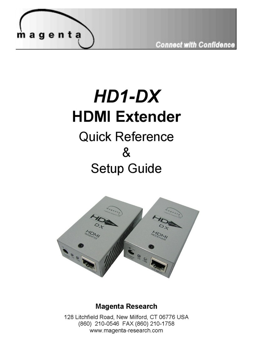
Magenta Research USB Link II User manual

USB Link II
User Guide
Magenta Research
128 Litchfield Road, New Milford, CT 06776 USA
(860) 210-0546 FAX (860) 210-1758
www.magenta-research.com

© 1998-2010 by Magenta Research All rights reserved.
Magenta Research
128 Litchfield Road
New Milford, CT 06776 USA
This document and the Magenta Research products to which it relates, and the copyright
in each, is the property of Magenta Research. Neither the document nor the products may
be reproduced by any means, in whole or in part, without the prior written permission of
Magenta Research. Magenta Research makes no warranty or representation, either
express or implied, with respect to this software or documentation, including their quality,
performance, merchantability, or fitness for a particular purpose. As a result, this
software or documentation are licensed "as is" and you, the licensee, are assuming the
entire risk as to their quality and performance.
In no event will Magenta Research be liable for direct, indirect, special, incidental, or
consequential damages arising out of the use of or inability to use the software or
documentation.
Magenta Research and the Magenta Research logo are trademarks of Magenta Research.
All other brands, product names, and trademarks are the property of their respective
owners.
MAGENTA USB LINK II

FCC Radio Frequency Interference Statement Warning
The USB Link II has been tested and found compliant with the limits for a Class A digital device,
pursuant to Part 15 of the FCC Rules. These limits are designed to provide reasonable protection
against harmful interference when installed and operated in a commercial environment. The USB
Link II generates, uses, and can radiate radio frequency energy and, if not installed and used in
accordance with this user guide, may cause harmful interference to radio communications.
Operation of the USB Link II in a residential area is likely to cause harmful interference in which
case the user will be required to correct the interference at his own expense.
CE Statement
We, Magenta Research, declare under our sole responsibility that the USB Link II, to which this
declaration relates, is in conformity with European Standard EN 55022/A1 Class A, and
EN 50082-1 (IEC 801-2, IEC 801-3, IEC 801-4)
SAFETY WARNING
Installation • This equipment is to be installed in a restricted access location.
Connection • Not for direct connection to Telecommunication Network Circuitry (TNV)
Power sources • This equipment should be operated only from the power source indicated on
the product. This equipment is intended to be used with a main power system with a grounded
(neutral) conductor. The third (grounding) pin is a safety feature, do not attempt to bypass or
disable it. This equipment can be powered from redundant power sources. Disconnect all power
sources before servicing.
Power disconnection • To remove power from the equipment safely, remove all power cords
from the rear of the equipment, or from the power source receptacle (wall plug).
Power cord protection • Power cords should be routed so that they are not likely to be stepped
on or pinched by items placed upon or against them.
Servicing • Refer all servicing to qualified service personnel. There are no user-serviceable parts
inside. To prevent the risk of shock, do not attempt to service this equipment yourself because
opening or removing covers may expose you to dangerous voltage or other hazards.
Slots and openings • If the equipment has slots or holes in the enclosure, these are provided to
prevent overheating of sensitive components inside. These openings must never be blocked by
other objects.
FCC/IC RFI STATEMENTS, SAFETY WARNING.
1

Contents
Specifications.................................................................................................3
Introduction....................................................................................................4
USB Link Product Contents...........................................................................4
The Transmitter Unit………………………………………………………………5
The Receiver Unit…………………………………………………………………6
Cables, Power, & Compatibility………………………………………………….7
Before You Begin...........................................................................................9
Installing the TRANSMITTER Unit.................................................................9
Installing the RECEIVER Unit........................................................................9
Connecting the TRANSMITTER Unit to the RECEIVER Unit......................10
Checking the Installation..............................................................................11
Connecting a USB Device...........................................................................11
Troubleshooting...........................................................................................12
2
MAGENTA USB LINK II

3
Range (over Category 5
UTP cable)
150 meters (492 ft)
USB device support High speed devices (480 Mb/s)
Full speed devices (12 Mb/s)
Low speed devices (1.5 Mb/s)
USB hub support Any single chain can include four USB hubs and one
Link, in any order.
Power available to USB
device at TRANSMITTER
1 x 500 mA
Power available to USB
device at RECEIVER
4 x 550 mA
USB cable 2 meters (6.6 ft)
TRANSMITTER connector
(upstream)
1 x USB Type B
TRANSMITTER connector
(downstream)
1 x RJ-45
RECEIVER connector
(upstream)
1 x RJ-45
RECEIVER connector
(downstream)
4 x USB Type A (Hub)
TRANSMITTER dimen-
sions 110 mm x 88 mm x 30 mm
4.3” x 3.5” x 1.2”
TRANSMITTER weight 280 g (0.6 lbs.)
RECEIVER dimensions 140 mm x 88 mm x 30 mm
5.5” x 3.5” x 1.2”
RECEIVER weight 330 g (0.73 lbs.)
Humidity Up to 95%
Temperature range Operation: 0°C to 55°C, Storage: -20°C to 85°C
Specifications
Specifications

Introduction
Introduction
This manual is intended to assist with the installation of the USB Link II. The
instructions in this guide assume a general knowledge of computer installation
procedures, familiarity with cabling requirements, and some understanding of
USB devices.
NOTE:Notes give additional information that could make
installation easier.
USB Link II Product Contents
When you open your USB Link II for the first time you should find the following
items:
USB Link II User Guide
Local Transmitter
Remote Receiver
AC power adapter
USB cable(6 ft)
To complete the installation, you will also require the following items that are
not included with the product:
USB compatible computer
USB device
Category 5/6 Unshielded Twisted Pair (UTP) cable with two RJ45
connectors pinned to the T568B specification.
NOTE: The maximum length of the Category 5/6 UTP cable,
including patch cords, must not exceed 492 ft (150m).
4
MAGENTA USB LINK II

The USB Link II is composed of two individual units, the Local transmitter and
the Remote Receiver.
The Transmitter Unit
The transmitter unit connects to the host computer using a conventional USB
cable.
Front View Rear View
1Host Port (USB Type B)
2 Power LED (ON)
3 Link LED (LINK)
4Link Port (RJ45)
5
2 3
1
4
Transmitter

Receiver
The Receiver Unit
The receiver unit connects to the USB device using a conventional USB
cable. It also must be connected to a power outlet through an AC power
adapter. The receiver unit allows you to connect up to four USB devices.
Front View Rear View
1Power Connector
2Power LED (ON)
3Link LED (LINK)
4Link Port (RJ45)
54-Port USB Hub (USB Type A)
6
1 2 3 4 5
MAGENTA USB LINK II

Network Cabling
The transmitter and receiver units are interconnected by up to 150 meters of
Category 5/6 Unshielded Twisted Pair (UTP) cabling. The UTP cabling must
have a straight-through conductor configuration, with no crossovers, and must
be terminated with T568B specified RJ45 connectors at both ends.
NOTE:Category 5/6 UTP cabling is the standard data
communications cable installed in most commercial and
some residential buildings.
USB Cables
USB cables have two distinct connectors. The Type A connector is used to
connect the cable from a USB device to the Type A port on a computer or
hub. The Type B connector is used to attach the USB cable to a USB device.
7
USB Type A
port
USB Type A
connector
USB Type B
port
USB Type B
connector
Cables, Power, & Compatibility
Transmitter Receiver

Cables, Power, & Compatibility cont.
8
Power Handling
Some USB devices are powered directly from the USB and do not require
individual power supplies. These devices are called bus-powered devices.
The USB Link II can provide power to these devices so they can be operated
remotely.
Bus-powered devices are further divided into low-power and high-power cate-
gories. Low-power devices are allowed to draw up to 100 mA from the USB.
Typical examples include mice, joysticks, and keyboards without hubs. High-
power devices are allowed to draw up to 550 mA from the USB. Typical ex-
amples include cameras and keyboards with hubs. To determine if a device is
high-power or low-power, consult the user documentation for the device.
NOTE: Devices with their own power source are usually considered to be
low-power devices from a USB perspective.
Compatibility
The USB Link II complies with USB 2.0 and 1.1 specifications governing the
design of full speed USB devices. However Magenta Research does not
guarantee that all full speed USB devices are compatible with the USB Link II.
MAGENTA USB LINK II

Before You Begin
Before You Begin
Before you can install the USB Link II, you need to prepare your site:
1. Determine where the host computer is to be located and set up the
computer.
2. Determine where you want to locate the USB device(s).
3. Ensure you have enough Category 5/6 UTP cabling to connect the
two locations. (Maximum 492 ft or 150 m)
Installing the TRANSMITTER Unit
1. Place the TRANSMITTER unit near the host computer.
2. Plug the Type B connector on the USB cable (included) into the
Host port on the TRANSMITTER.
3. Plug the Type A connector on the USB cable into the USB port on
the computer.
NOTE:There is no separate power supply required for the
Transmitter unit.
Installing the RECEIVER Unit
1. Place the RECEIVER unit near the USB device(s).
2. Plug the power adapter into a suitable AC outlet.
3. Connect the power adapter to the RECEIVER unit.
9

10
Connecting the Transmitter and Receiver
Connecting the TRANSMITTER Unit to the RECEIVER Unit
NOTE:To ensure proper operation, we recommend that only
Category 5 or better, Unshielded Twisted Pair (UTP) cabling be used to
connect the TRANSMITTER unit to the RECEIVER unit. The UTP cabling
must have a straight-through conductor configuration with no crossovers, and
must be terminated with T568B specified RJ45 connectors at both ends.
1. Plug one end of the Category 5/6 UTP cabling (not included) into
the Link port on the TRANSMITTER unit.
2. Plug the other end of the Category 5/6 UTP cabling into the Link
port on the RECEIVER unit.
MAGENTA USB LINK II

Checking the Installation
1. Check that the Power LEDs on the TRANSMITTER and
RECEIVER units are both on.
2. Check that the Link LEDs on the TRANSMITTER and RECEIVER
units are both on.
3. On the host PC, open the Device Manager applet. Expand the
entry for Universal Serial Bus controllers by clicking the “+” sign. If the USB
Link II has been installed correctly you should find it listed as a Generic USB
Hub.
Connecting a USB Device
1. Install any software required to operate the USB device(s). Refer
to the documentation for the device(s), as required.
2. Connect the USB device(s) to the device port on the RECEIVER
unit.
11
Checking and Connecting

12
Troubleshooting
Troubleshooting
The following tables provide troubleshooting help. The topics are arranged in
the order in which they should be executed in most situations. If you are
unable to resolve the problem after following these instructions, please
contact Magenta Research technical support for further assistance.
Symptoms/Cause Remedy
Power LEDs on TRANS-
MITTER and RECEIVER
are off.
Cause:
The USB Link is not re-
ceiving power
1. Ensure that the power adapter is connected to the
RECEIVER unit
2. Ensure PC USB Port is active.
3. Check that the adapter is connected to a live
source of electrical power.
Link LEDs on TRANS-
MITTER and RECEIVER
are off.
Cause:
There is no connection
between the TRANSMIT-
TER and RECEIVER
units.
1. Ensure that a Category 5 UTP cable with straight-
through conductors is connected between the
TRANSMITTER and RECEIVER units.
2. Connect a short Category 5 patch cord between the
TRANSMITTER and RECEIVER units. Recheck
the operation of the system.
MAGENTA USB LINK II

Troubleshooting cont.
13
Symptoms/Cause Remedy
Link LED on TRANSMITTER
is on; Host LED on TRANS-
MITTER is off.
Cause:
1. The computer is not func-
tioning. The TRANSMIT-
TER unit is not connected
to the computer.
2. The computer does not
support USB hubs.
3. The USB Link is malfunc-
tioning.
1. Disconnect all USB devices from the RE-
CEIVER unit.
2. Disconnect TRANSMITTER from the computer.
3. Disconnect and then reconnect the power
adapter to the Link.
4. Reconnect the TRANSMITTER unit to the com-
puter.
5. In the Universal Serial Bus controllers section
of Device Manager, check that the Link is rec-
ognised as a “Generic USB Hub”.

Magenta Research
128 Litchfield Road, New Milford, CT 06776 USA
(860) 210-0546 FAX (860) 210-1758
www.magenta-research.com
PN: 5310243-01, rev. 01, Jan. 2010
This manual suits for next models
1
Table of contents
Other Magenta Research Extender manuals