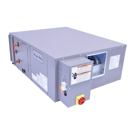
Magic Aire HHA Series User manual

035-000029-001 Page 1 HHA IOM 1.4 10/11/2021
How to Use this Manual:
This manual gives instructions regarding instal-
lation, operation and maintenance for the HHA
Series air handling units. For more information
refer to:
Catalog brochure for unit dimensions, op-
tions, guide specifications and performance
information.
New Magic 4 software for faster selection
of new equipment.
Website www.magicaire.com for replace-
ment parts guide, software downloads,
product data and contact info for your local
Magic Aire representative.
Replacement Parts – Identify parts need-
ed using the replacement parts guide avail-
able at www.magicaire.com.
Use these instructions in conjunction with other
appropriate instructions, including but not lim-
ited to those instructions supplied with the out-
door unit (if applicable). Installation must com-
ply with all applicable local codes.
GENERAL
Installation and maintenance are to be performed
only by qualified personnel who are familiar with
local codes and regulations and are experienced
with HVAC equipment of this type.
WARNING: Sharp edges, coil surfaces and
rotating fans are a potential injury hazard –
avoid contact.
WARNING: Hazardous voltage – Discon-
nect and Lock Out all incoming power
sources before servicing or installing unit.
ELECTRIC SHOCK CAN CAUSE DEATH.
WARNING: This equipment may be in-
stalled well above finished floor—Use ex-
treme caution when working at heights.
SAFETY WARNING:
Installer should pay particular attention to the
following words:
NOTE–intended to clarify or make installation
easier.
CAUTION–given to prevent equipment dam-
age.
WARNING–to alert installer that personal in-
jury and/or equipment damage may result if
installation procedure is not properly followed.
HHA Series Air Handler
Installation, Operation and Maintenance
Manual
UNPACKING-CHECK FOR DAMAGE!
Immediately inspect each unit for damage up-
on receipt.
Inspect units for external and concealed dam-
age immediately.
File any damage claims in accordance with
Magic Aire Freight Damage Policy and Terms
and Conditions (available at
www.magicaire.com).
Do not repair damaged units without written
authorization.
Protect stored units from damage.
DANGER
VFD Energy Stored!
Dangerous voltage is present when input power is
connected. After disconnecting power supply
wait at least 5 minutes before performing any
maintenance.
Magic Aire HHA Series units are
direct drive High Static Horizontal
Air Handlers delivering nominal
airflows of 300 to 5000cfm and
nominal cooling capacities of 1/2
to 10 tons. Units may be specified
with chilled water or DX cooling coils
and hot water or steam heating coils
to meet space cooling loads or heat-
ing loads or both.

035-000029-001 Page 2 HHA IOM 1.4 10/11/2021
THIS PAGE INTENTIONALLY LEFT BLANK

035-000029-001 Page 3 HHA IOM 1.4 10/11/2021
Table of Contents
HHA Series Air Handler
Installation, Operation and Maintenance
Manual
Topic Page
SAFETY CONSIDERATIONS 1,4
UNPACKING-Remove Shipping Screws 4
PREINSTALLATION 5
Rigging 5
Unit Weight Calculation 5
Unit Suspension 6
External Vibration Isolators 6 - 7
INSTALLATION 8
Electrical 8 - 23
Service Clearance 24 - 25
Condensate Drain 26
Steam Coil Piping
Recommendations 27 - 30
Coil Freeze-Up Protection 29
Refrigerant Piping, Direct
Expansion (DX) Coils 30 - 31
APD Gauge Option 32
Static Pressure Ports Option 33
Filter Pressure Drop Tables 34
START-UP 35
Fan Curves 36 - 38
SERVICE - Periodic Maintenance &
Replacement 39
Fan Motor 39 - 40
Coil 41 - 44
UV Light 45
VFD Parameters 46 - 51
Water Quality Guidelines 52
Physical Data 53 - 54
Dimensional Drawings 55 - 58
UV Light Accessory 59
HEPA Diffuser Accessory 60 - 62
WARRANTY REGISTRATION FORM 64
REPLACEMENT PARTS 65

035-000029-001 Page 4 HHA IOM 1.4 10/11/2021
WARNING
CHECK the assembly and component weights to
be sure that the rigging equipment can handle
them safely.
Note also, the centers of gravity and any specific
rigging instructions.
CHECK for adequate ventilation so that fumes will
not migrate through ductwork to occupied spaces
when welding or cutting inside air-handling unit
cabinet or plenum.
WHEN STEAM CLEANING COILS be sure that
the area is clear of personnel.
DO NOT attempt to handle access covers and re-
movable panels on outdoor units when winds are
strong or gusting until you have sufficient help to
control them. Make sure panels are properly se-
cured while repairs are being made to a unit.
DO NOT remove access panel fasteners or open
access doors until fan is completely stopped. Pres-
sure developed by a moving fan can cause exces-
sive force against the panel which can injure per-
sonnel.
DO NOT work on dampers until their operators are
disconnected.
BE SURE that fans are properly grounded before
working on them.
Failure to follow these warnings could result in per-
sonal injury or equipment damage.
DANGER
NEVER enter an enclosed fan cabinet or reach into
a unit while the fan is running.
LOCK OPEN AND TAG the fan motor power dis-
connect switch before working on a fan. Take fuses
with you and note removal on tag. Electric shock
can cause personal injury or death.
LOCK OPEN AND TAG the electric heat coil power
disconnect switch before working on or near heat-
ers.
TURN OFF POWER to UVC lights before servicing
or repairing.
Failure to follow these warnings could lead to per-
sonal injury or death.
UNPACKING-CAUTION!
After removing the outer packaging,
REMOVE RED BRACKET SCREWS
from the shipping pallet brackets as shown
in Figure 1a. Remove shipping brackets.
REINSTALL the bracket screws into the unit
side (Figure 1b).
REMOVE RED BLOWER SHIPPING
SCREWS
from the blower supports as indicated in Fig-
ure 2. These screws stabilize the fan as-
sembly during shipping and need to be re-
moved.
CAUTION! Not removing red shipping
screws can result in unsatisfactory vibration
or blower noise.
Figure 2
Remove Red Shipping Screws–
Blower (1ea per side, 2ea total)
Figure 1a,b
Remove Shipping Brackets and Rein-
stall Bracket Screws (multiple loca-
tions)
SHIPPING
BRACKET
BRACKET
SCREW
BRACKET
SCREW
Figure 1a
Figure 1b

035-000029-001 Page 5 HHA IOM 1.4 10/11/2021
PREINSTALLATION
1. Check items received against packing list.
2. Do not stack unit components or accessories
during storage. Stacking can cause damage or
deformation.
3. If unit is to be stored for more than 2 weeks
prior to installation, observe the following pre-
cautions:
a. Choose a dry storage site that is reasona-
bly level and sturdy to prevent undue
stress or permanent damage to the unit
structure or components. Do not store unit
on vibrating surface. Damage to stationary
bearings can occur. Set unit off ground if
in heavy rain area.
b. Remove all fasteners and other small
parts from jobsite to minimize theft. Tag
and store parts in a safe place until need-
ed.
c. Cover entire unit with a tarp or plastic cov-
erall. Extend cover under unit if stored on
ground. Secure cover with adequate tie-
downs or store indoors. Be sure all coil
connections have protective shipping
caps.
d. Monthly — Remove tarp from unit, enter
fan section through access door or
through fan inlet, and rotate fan and motor
slowly by hand to redistribute the bearing
grease and to prevent bearing corrosion.
Rigging — Do not remove shipping skids or pro-
tective covering until unit is ready for final place-
ment. Use slings and spreader bars as applicable
to lift unit. Do not lift unit by coil connections or
headers.
Do not remove protective caps from coil piping
connections until ready to connect piping.
Do not remove protective cover or grease
from fan shaft until ready to install sheave.
Lay rigid temporary protection such as ply-
wood walkways in unit to prevent damage to
insulation or bottom panel during installation.
WARNING-AUXILIARY DRAIN PAN
RECOMMMENDED:
This product has an auxiliary condensate
drain which should be piped to a conden-
sate overflow sensor or safe drain location
or both to protect the equipment and proper-
ty from damage in the case of condensate
overflow.
In addition, the International Mechanical
Code (IMC) section 307.2.3 requires the use
of auxiliary drain pans. Many municipalities
have adopted this code.
Magic Aire holds that this practice repre-
sents the standard for professional installa-
tion whether or not this code has been
adopted in a specific municipality or territo-
ry. As such, water damages that would
have been prevented had an auxiliary pan
been deployed will not be considered for
compensation. This position is taken re-
gardless of whether the source of the mois-
ture was specified as a potential failure
mode in the applicable building code or not.
A freeze burst, cracked drain pan, failed
weld, or corrosion induced leak are some of
the potential failure modes that are mitigat-
ed when an auxiliary pan is properly in-
stalled. Professional installers recognize
the value of protecting customer assets
against foreseeable events. Customers
who choose to avoid the cost of common
protective measures waive their right to
seek damages when those foreseeable
events occur. If the product is located
above a living space or where damage may
result from condensate overflow, install a
watertight pan of corrosion-resistant metal
beneath the unit to catch over-flow which
may result from clogged drains or from other
reasons. Provide proper drain piping for this
auxiliary pan. Consult local codes for addi-
tional precautions before installation.
Calculation Procedure:
1. Calculate coil water weight for each water
coil using the following formula:
Water Weight =
Coil Volume (gal) x 8.345lb/gal
(volume is from Physical Data table)
2. Calculate total weight:
Total Unit Installed Weight =
Unit Dry Weight + Water Weight (coil 1)
+ Water Weight (coil 2)
Table 1 — Unit Dry Weight
UNIT WEIGHT CALCULATION
Unit Weights
Size Cabinet* Dry Weight
(lbs)
04/06 B 503
04/06 D 772
08/12 B 516
08/12 D 785
16/20/25 B 880
16/20/25 D 1085
30/40 B 1597
30/40 D 1854
*Model Codestring digit #6, ex. HHA12B

035-000029-001 Page 6 HHA IOM 1.4 10/11/2021
UNIT SUSPENSION
Ceiling Suspension: Acceptable forms of unit sus-
pension are shown in Fig. 3, 4, 5a and 5b. A field-
supplied platform mount is recommended, espe-
cially for larger unit sizes. Units can also be sup-
ported by suspending the unit from lengthwise
(direction of airflow) beams. Size suspension
rods to support the weight. Size any beam mem-
bers to insure that they are adequate for a safe
installation. Ensure that suspension rods are se-
cured to adequately support the unit and that the
rods extend entirely through their associated fas-
teners.
It is recommended that framing be constructed
from structural steel or formed-strut materials.
Size 30 and 40 units have hanging brackets with
specific recommendations – see Fig. 5b.
Fig. 5a
Ceiling Suspension—
Alternate Lengthwise
Beam Mount
Fig. 4
Ceiling Suspension—
Crossbeam Mount
HHA04-25
WARNING! INSURE THAT UNIT IS ADE-
QUATELY SUPPORTED FROM STRUCTURE
TO PREVENT DAMAGE OR INJURY CAUSED
BY FALLING EQUIPMENT! If uncertain about
how to connect to the structure, consult a
qualified structural engineer.
Floor mounting: Unit may be mounted on a
housekeeping pad, floor or platform. CAUTION!
Make sure to allow enough elevation to per-
mit construction of the condensate drain
trap.
Vibration Isolators: (field supplied) If required,
install isolators in the suspension rod system.
Allow clearance as needed between isolators
and unit.
Fig. 3
Ceiling Suspension—
Platform Mount

035-000029-001 Page 7 HHA IOM 1.4 10/11/2021
UNIT SUSPENSION (cont’d) Fig. 5b—Ceiling Suspension– HHA30/40—Hanging Brackets

035-000029-001 Page 8 HHA IOM 1.4 10/11/2021
Typical wiring diagrams are shown on the following
pages FOR REFERENCE. Always refer to the wir-
ing diagram on the air handling unit for actual wiring.
Connect electrical service to unit. Refer to unit wiring
diagram. NOTE: CHECK MOTOR RATING PLATE
FOR CORRECT LINE VOLTAGE. For power supply
connection, route field power wiring to field-provided
and installed disconnect switch and from switch to
junction box on unit. Unit is internally wired from
junction box to VFD.
Refer to nameplate FLA, maximum overcurrent pro-
tection device (MOPD) and minimum circuit ampacity
(MCA). Also refer to wiring diagram affixed to unit to
make control and power wiring connections.
NOTE: Installer is responsible for power wiring and
branch circuit over current protection.
All field-installed wiring, including the electrical
ground, MUST comply with the National Electri-
cal Code (NEC) as well as applicable local
codes. In addition, all field wiring must conform
to the Class II temperature limitations described
in the NEC.
Refer to factory wiring diagrams installed in the
unit.
CAUTION
Use only copper conductors for field
-installed electrical wiring. Unit ter-
minals are not designed to accept
other types of conductors.
DANGER
WARNING: Hazardous voltage. Only qualified
personnel must install the electrical service. Dis-
connect and Lock Out all incoming power sources
before connecting to electrical service.
WARNING: This appliance must be permanently
grounded in accordance with the National Electrical
Code and local code requirements.
WARNING: For use with copper conductors only.
DANGER
VFD Energy Stored!
Dangerous voltage is present when input power is
connected. After disconnecting power supply wait
at least 5 minutes before performing any mainte-
nance.
INSTALLATION-ELECTRICAL DANGER
NEVER enter an enclosed fan cabinet or reach
into a unit while the fan is running.
LOCK OPEN AND TAG the fan motor power dis-
connect switch before working on a fan. Take
fuses with you and note removal on tag. Electric
shock can cause personal injury or death.
LOCK OPEN AND TAG the electric heat coil
power disconnect switch before working on or
near heaters.
TURN OFF POWER to UVC lights before servic-
ing or repairing.
Failure to follow these warnings could lead to
personal injury or death.
Electrical Installation
WARNING
To avoid possible injury or death due to electrical
shock, open the power supply disconnect switch
and secure it in an open position during installation.

035-000029-001 Page 9 HHA IOM 1.4 10/11/2021
NOTES:
1. This diagram represents the factory-installed electrical option with 4-20mA field signal input for fan
speed control. Includes VFD keypad mounted on outside of unit.
2. Typical wiring is shown. For exact wiring, refer to the wiring diagram provided with the unit.
3. Field wiring includes power wiring (upper left hand corner) and low voltage control wiring (terminal
block TB1).
4. Units ordered for 208V-240V voltage selection are factory wired for 240V. Field may rewire motor and
transformer primary tap for operation at 208V.
5. Selection of field provided and installed electrical components is the responsibility of the installer, in-
cluding branch circuit protection and wiring.
6. To start the fan, connect R and G to energize fan relay FR1. Control fan speed by providing 4-20mA
signal at + and - connections at TB1.
7. The control power (R and C at terminal block TB1) can be used to power a standard 24VAC thermo-
stat , DX relay and up to 2ea control valves.
INSTALLATION-ELECTRICAL (cont’d)
TYPICAL WIRING DIAGRAMS—
Control Option “A”, 4-20mA Fan Speed Control
208/230V—1ø

035-000029-001 Page 10 HHA IOM 1.4 10/11/2021
NOTES:
1. This diagram represents the factory-installed electrical option with 4-20mA field signal input for fan
speed control. Includes VFD keypad mounted on outside of unit.
2. Typical wiring is shown. For exact wiring, refer to the wiring diagram provided with the unit.
3. Field wiring includes power wiring (upper left hand corner) and low voltage control wiring (terminal
block TB1).
4. Selection of field provided and installed electrical components is the responsibility of the installer, in-
cluding branch circuit protection and wiring.
5. To start the fan, connect R and G to energize fan relay FR1. Control fan speed by providing 4-20mA
signal at + and - connections at TB1.
6. The control power (R and C at terminal block TB1) can be used to power a standard 24VAC thermo-
stat , DX relay and up to 2ea control valves.
INSTALLATION-ELECTRICAL (cont’d)
TYPICAL WIRING DIAGRAMS—
Control Option “A”, 4-20mA Fan Speed Control
277V—1ø

035-000029-001 Page 11 HHA IOM 1.4 10/11/2021
NOTES:
1. This diagram represents the factory-installed electrical option with 4-20mA field signal input for fan
speed control. Includes VFD keypad mounted on outside of unit.
2. Typical wiring is shown. For exact wiring, refer to the wiring diagram provided with the unit.
3. Field wiring includes power wiring (upper left hand corner) and low voltage control wiring (terminal
block TB1).
4. Units ordered for 208V-240V voltage selection are factory wired for 240V. Field may rewire motor and
transformer primary tap for operation at 208V.
5. Selection of field provided and installed electrical components is the responsibility of the installer, in-
cluding branch circuit protection and wiring.
6. To start the fan, connect R and G to energize fan relay FR1. Control fan speed by providing 4-20mA
signal at + and - connections at TB1.
7. The control power (R and C at terminal block TB1) can be used to power a standard 24VAC thermo-
stat , DX relay and up to 2ea control valves.
INSTALLATION-ELECTRICAL (cont’d)
TYPICAL WIRING DIAGRAMS—
Control Option “A”, 4-20mA Fan Speed Control
208/240V—3ø

035-000029-001 Page 12 HHA IOM 1.4 10/11/2021
NOTES:
1. This diagram represents the factory-installed electrical option with 4-20mA field signal input for fan
speed control. Includes VFD keypad mounted on outside of unit.
2. Typical wiring is shown. For exact wiring, refer to the wiring diagram provided with the unit.
3. Field wiring includes power wiring (upper left hand corner) and low voltage control wiring (terminal
block TB1).
4. Selection of field provided and installed electrical components is the responsibility of the installer, in-
cluding branch circuit protection and wiring.
5. To start the fan, connect R and G to energize fan relay FR1. Control fan speed by providing 4-20mA
signal at + and - connections at TB1.
6. The control power (R and C at terminal block TB1) can be used to power a standard 24VAC thermo-
stat , DX relay and up to 2ea control valves.
INSTALLATION-ELECTRICAL (cont’d)
TYPICAL WIRING DIAGRAMS—
Control Option “A”, 4-20mA Fan Speed Control
480V—3ø

035-000029-001 Page 13 HHA IOM 1.4 10/11/2021
NOTES:
1. This diagram represents the factory-installed electrical option with 4-20mA field signal input for fan
speed control. Includes VFD keypad mounted on outside of unit. Includes UVC light option with door
switches to protect workers from harmful high energy UVC exposure that can damage skin and eyes.
2. Typical wiring is shown. For exact wiring, refer to the wiring diagram provided with the unit.
3. Field wiring includes power wiring (upper left hand corner) and low voltage control wiring (terminal block
TB1).
4. Units ordered for 208V-240V voltage selection are factory wired for 240V. Field may rewire motor and
transformer primary tap for operation at 208V.
5. Selection of field provided and installed electrical components is the responsibility of the installer, in-
cluding branch circuit protection and wiring.
6. To start the fan, connect R and G to energize fan relay FR1. Control fan speed by providing 4-20mA
signal at + and - connections at TB1.
7. The control power (R and C at terminal block TB1) can be used to power a standard 24VAC thermo-
stat , DX relay and up to 2ea control valves.
INSTALLATION-ELECTRICAL (cont’d)
TYPICAL WIRING DIAGRAMS—
Control Option “A”, 4-20mA Fan Speed Control
208/230V—3øwith UV light option

035-000029-001 Page 14 HHA IOM 1.4 10/11/2021
NOTES:
1. This diagram represents the factory-installed electrical option with manual fan speed control using the
VFD keypad mounted on outside of unit.
2. Typical wiring is shown. For exact wiring, refer to the wiring diagram provided with the unit.
3. Field wiring includes power wiring (upper left hand corner) and low voltage control wiring (terminal
block TB1).
4. Units ordered for 208V-240V voltage selection are factory wired for 240V. Field may rewire motor and
transformer primary tap for operation at 208V.
5. Selection of field provided and installed electrical components is the responsibility of the installer, in-
cluding branch circuit protection and wiring.
6. To start the fan, connect R and G to energize fan relay FR1. Control fan speed using the keypad.
7. The control power (R and C at terminal block TB1) can be used to power a standard 24VAC thermo-
stat , DX relay and up to 2ea control valves.
INSTALLATION-ELECTRICAL (cont’d)
TYPICAL WIRING DIAGRAMS—
Control Option “B”, Manual Fan Speed Control
208/230V—1ø

035-000029-001 Page 15 HHA IOM 1.4 10/11/2021
NOTES:
1. This diagram represents the factory-installed electrical option with manual fan speed control using the
VFD keypad mounted on outside of unit.
2. Typical wiring is shown. For exact wiring, refer to the wiring diagram provided with the unit.
3. Field wiring includes power wiring (upper left hand corner) and low voltage control wiring (terminal
block TB1).
4. Units ordered for 208V-240V voltage selection are factory wired for 240V. Field may rewire motor and
transformer primary tap for operation at 208V.
5. Selection of field provided and installed electrical components is the responsibility of the installer, in-
cluding branch circuit protection and wiring.
6. To start the fan, connect R and G to energize fan relay FR1. Control fan speed using the keypad.
7. The control power (R and C at terminal block TB1) can be used to power a standard 24VAC thermo-
stat , DX relay and up to 2ea control valves.
INSTALLATION-ELECTRICAL (cont’d)
TYPICAL WIRING DIAGRAMS—
Control Option “B”, Manual Fan Speed Control
277V—1ø

035-000029-001 Page 16 HHA IOM 1.4 10/11/2021
NOTES:
1. This diagram represents the factory-installed electrical option with manual fan speed control using the
VFD keypad mounted on outside of unit. Includes UVC light option with door switches to protect work-
ers from harmful high energy UVC exposure that can damage skin and eyes.
2. Typical wiring is shown. For exact wiring, refer to the wiring diagram provided with the unit.
3. Field wiring includes power wiring (upper left hand corner) and low voltage control wiring (terminal
block TB1).
4. Units ordered for 208V-240V voltage selection are factory wired for 240V. Field may rewire motor and
transformer primary tap for operation at 208V.
5. Selection of field provided and installed electrical components is the responsibility of the installer, in-
cluding branch circuit protection and wiring.
6. To start the fan, connect R and G to energize fan relay FR1. Control fan speed using the keypad.
7. The control power (R and C at terminal block TB1) can be used to power a standard 24VAC thermo-
stat , DX relay and up to 2ea control valves.
INSTALLATION-ELECTRICAL (cont’d)
TYPICAL WIRING DIAGRAMS—
Control Option “B”, Manual Fan Speed Control
208/230V—1ø with UV Light Opon

035-000029-001 Page 17 HHA IOM 1.4 10/11/2021
NOTES:
1. This diagram represents the factory-installed electrical option with manual fan speed control using the
VFD keypad mounted on outside of unit.
2. Typical wiring is shown. For exact wiring, refer to the wiring diagram provided with the unit.
3. Field wiring includes power wiring (upper left hand corner) and low voltage control wiring (terminal
block TB1).
4. Units ordered for 208V-240V voltage selection are factory wired for 240V. Field may rewire motor and
transformer primary tap for operation at 208V.
5. Selection of field provided and installed electrical components is the responsibility of the installer, in-
cluding branch circuit protection and wiring.
6. To start the fan, connect R and G to energize fan relay FR1. Control fan speed using the keypad.
7. The control power (R and C at terminal block TB1) can be used to power a standard 24VAC thermo-
stat , DX relay and up to 2ea control valves.
INSTALLATION-ELECTRICAL (cont’d)
TYPICAL WIRING DIAGRAMS—
Control Option “B”, Manual Fan Speed Control
208/240V—3ø

035-000029-001 Page 18 HHA IOM 1.4 10/11/2021
NOTES:
1. This diagram represents the factory-installed electrical option with manual fan speed control using the
VFD keypad mounted on outside of unit.
2. Typical wiring is shown. For exact wiring, refer to the wiring diagram provided with the unit.
3. Field wiring includes power wiring (upper left hand corner) and low voltage control wiring (terminal
block TB1).
4. Selection of field provided and installed electrical components is the responsibility of the installer, in-
cluding branch circuit protection and wiring.
5. To start the fan, connect R and G to energize fan relay FR1. Control fan speed using the keypad.
6. The control power (R and C at terminal block TB1) can be used to power a standard 24VAC thermo-
stat , DX relay and up to 2ea control valves.
INSTALLATION-ELECTRICAL (cont’d)
TYPICAL WIRING DIAGRAMS—
Control Option “B”, Manual Fan Speed Control
480V—3ø

035-000029-001 Page 19 HHA IOM 1.4 10/11/2021
NOTES:
1. This diagram represents the factory-installed electrical option with manual fan speed control using the
VFD keypad mounted on outside of unit. Includes UVC light option with door switches to protect work-
ers from harmful high energy UVC exposure that can damage skin and eyes.
2. Typical wiring is shown. For exact wiring, refer to the wiring diagram provided with the unit.
3. Field wiring includes power wiring (upper left hand corner) and low voltage control wiring (terminal
block TB1).
4. Units ordered for 208V-240V voltage selection are factory wired for 240V. Field may rewire motor and
transformer primary tap for operation at 208V.
5. Selection of field provided and installed electrical components is the responsibility of the installer, in-
cluding branch circuit protection and wiring.
6. To start the fan, connect R and G to energize fan relay FR1. Control fan speed using the keypad.
7. The control power (R and C at terminal block TB1) can be used to power a standard 24VAC thermo-
stat , DX relay and up to 2ea control valves.
INSTALLATION-ELECTRICAL (cont’d)
TYPICAL WIRING DIAGRAMS—
Control Option “B”, Manual Fan Speed Control
480V—3ø with UV Light Opon

035-000029-001 Page 20 HHA IOM 1.4 10/11/2021
NOTES:
1. This diagram represents the factory-installed electrical option with constant CFM control using the pres-
sure transducer mounted inside the unit. Control loop logic is contained in the VFD programming. VFD
keypad is mounted on outside of unit.
2. Typical wiring is shown. For exact wiring, refer to the wiring diagram provided with the unit.
3. Field wiring includes power wiring (upper left hand corner) and low voltage control wiring (terminal block
TB1).
4. Units ordered for 208V-240V voltage selection are factory wired for 240V. Field may rewire motor and
transformer primary tap for operation at 208V.
5. Selection of field provided and installed electrical components is the responsibility of the installer, in-
cluding branch circuit protection and wiring.
6. To start the fan, connect R and G to energize fan relay FR1. Fan speed is controlled by the VFD using
the pressure transducer signal to maintain a fixed airflow (constant pressure difference across the cali-
brated fan nozzle). See “VFD Parameter” section for airflow adjustment.
7. The control power (R and C at terminal block TB1) can be used to power a standard 24VAC thermo-
stat , DX relay and up to 2ea control valves.
INSTALLATION-ELECTRICAL (cont’d)
TYPICAL WIRING DIAGRAMS—
Control Option “D”, Constant CFM Control
208/230V—1ø
Table of contents
Other Magic Aire Air Handler manuals
Popular Air Handler manuals by other brands

Salda
Salda RIRS 2500 HE EKO 3.0 QUICK LAUNCH GUIDE

Swegon
Swegon GLOBAL PX Operation and maintenance instructions

ClimateMaster
ClimateMaster OA Series Application, Operation and Maintenance Manual

Daikin
Daikin DSC Series installation instructions

LG
LG PAHCMR000 installation manual

Lennox
Lennox LRP14GN Series installation instructions

Lennox
Lennox VEOA042N432U Installation & operation instructions

Denco
Denco CAIRplus Operation manual

RDZ
RDZ RNW 214-I Technical installation manual

American Standard
American Standard A5AHV002A1B30AA Installation, operation and maintenance

flakt woods
flakt woods TopMaster manual

SIMNA
SIMNA PT1-B1 Series user manual